
A GENERIC SOLUTION FOR THE CONSTRUCTION OF
DIAGNOSTIC EXPERT SYSTEMS BASED ON PRODUCT LINES
Ma Eugenia Cabello Espinosa and Isidro Ramos Salavert
Polytechnic University of Valencia,Camino de Vera s/n, 46022 Valencia, Spain
Keywords: Expert Systems, Medical Diagnosis, Software Architectures, Reusability of Software, Software Product
Lines, Variability, Domain Engineering, Domain Application Engineering, Conceptual Models.
Abstract: This paper presents a generic solution for the construction of diagnostic expert systems using aspect-
oriented-software architectures and product line techniques. The approach is shown by specifying a case
study using CIMs, and automatically generating a PIM. The case study presented is a medical diagnosis
system for the detection of infantile infectious diseases. PRISMA models are used as PIMs. We follow the
Model Driven Architecture (MDA) initiative of the Object Management Group (OMG) for building domain
models (CIMs), which are automatically transformed into PIMs and are then compiled to a .NET executable
application (PSM). The Software Product Line techniques have been used to capture the variability of
systems of this kind.
1 INTRODUCTION
In the last few years, there has been an increase in
interest in expert systems that perform diagnostic
tasks. The main objective of systems of this kind is
to capture the state of an entity from a series of data
(observation variables) and produce a diagnosis. The
domain of expert systems for diagnosis includes
systems for medical and education diagnoses, among
others. Since systems for medical diagnosis have
become more relevant, the need of techniques for
their development has also become more important.
Additionally, expert systems introduce a difference
in the decision making process: they store expert
knowledge in a Knowledge Base.
In order to capture complex software
requirements, it is also necessy to increase the PIM
abstraction level. The PRISMA framework (Pérez,
2006) provides expresivity for specifying software
architectures with aspects at a design level. It offers
properties and advantages in the construction of
complex, distributed, evolutionary, and re-usable
architectural models that can be used in the domain
of expert systems for medical diagnosis.
Furthermore, the development of these complex
systems is becoming more elaborate due to a series
of factors. These factors are the emergence of new
technologies (Internet and intranet), the
interconnection of the different systems and
platforms, and to integrate Legacy Systems that are
still valid. Also, the need to develop custom
software for each type of user complicates the
specific aspects of systems in different
implementation platforms. This state of affairs
requires having multiple versions of the same
application in order to deal with all of this
variability.
In order to cope with this variability problem,
Software Product Lines (SPL) (Clements et al.,
2002) have emerged in an effort to control and
minimize the high costs of the software development
process and to reduce the time to market of these
new products. This approach is based on having a
base design that is shared by all the product family
members. Thus, a specific product can benefit from
the common parts of the software. The base design
can be re-used in different products by adding
different features that caracterize them.
We have built BOM (Base-Line Oriented
Modeling), wich is a framework that automatically
generates diagnostic systems based on software
product lines, to achieve the following goals:
to create new diagnostic systems in different
domains,
to decrease production costs by reusing
software packages or assets,
to generate automatic code to increase the
productivity and quality of software and to
decrease the time to market,
237
Eugenia Cabello Espinosa M. and Ramos Salavert I. (2008).
A GENERIC SOLUTION FOR THE CONSTRUCTION OF DIAGNOSTIC EXPERT SYSTEMS BASED ON PRODUCT LINES.
In Proceedings of the First International Conference on Health Informatics, pages 237-246
Copyright
c
SciTePress

to construct systems in a simpler way by using
the ontologies of the diagnosis and the
application domains. The models will be
closer to the problem domain, which will
facilitate user interaction,
to develop platform independent systems from
the problem perspective and not the solution
perspective, which will provide generality in
the development approach and applicability in
different domains.
The products of our Diagnostic Software Product
Line (DSPL) have been designed using the PRISMA
model and include the architecture and operations of
a rule-based expert system.
In this paper the development process of our
Diagnostic Software Product Line is presented using
a case study of infantile infectious diseases.
The structure of the paper is the following:
Section 2 introduces the relevant concepts of Expert
Systems, Model Driven Development, the PRISMA
Model, and Software Product Lines. Section 3
introduces the variability dimensions of our domain.
Section 4 provides an in-depth description of our
approach. Section 5 presents a brief summary of the
case study. Section 6 presents related works. Section
7 presents our conclusions and provides some ideas
for future work.
2 FOUNDATIONS
Our work integrates different technological spaces in
order to cope with the complexity of the problem.
These are the following:
2.1 Expert Systems
Expert systems capture the knowledge of experts
and try to imitate their reasoning processes when the
experts solve problems in a certain domain.
These systems usually have a basic architecture
that includes a knowledge base, an inference motor,
a working memory or facts base, and the user
interface. These are the four main components of the
architecture of a rule-based expert system.
These components are independent and are
composed of separates units. The data are grouped
into the working memory (temporary storage of
dynamic information). The representation of the
knowledge is captured by means of rules of the type:
IF <antecedent > THEN <conclusion>, which make
up the knowledge base. The control aspect is
independent and is performed by the inference motor
during the inference processes using different
reasoning strategies. The input and output of the
information of the systems are done through the user
interface.
2.2 Model Driven Development
The Model Driven Development approach (MDD)
for software system development is based on the
separation of the functionality of the system from its
implementation on specific software platforms.
MDD increases the abstraction level of the software
production process by emphasizing the importance
of the conceptual models - Computer Independent
Models (CIM) or Platform Independent Models
(PIM) - and their role in the software development
process.
There are currently two main initiatives in MDD.
One of them, which is promoted by the Object
Management Group (OMG) is called Model Driven
Architecture (MDA) (http://www.org.mda). The
other one, promoted by Microsoft, is called Software
Factories (SF) and Domain Specific Languages
(DSL) (Greenfield et al., 2004).
The key idea of MDA is to focus on the models
as first class citizens in the software development
process. MDA proposes defining and using models
at different abstraction levels. These models can
automatically generate code by means of mappings
or by applying transformation rules to executable
Platform Specific Models (PSM).
2.3 The PRISMA Model
The PRISMA architectural model integrates two
approaches: Component-Based Software
Development (CBSD) (Szyperski, 1998), and
Aspect-Oriented Software Development (AOSD).
(http://aosd.net) This integration is obtained by
defining the architectural elements through their
aspects.
The PRISMA model consists of three types of
architectural elements: components, connectors, and
systems. A component captures the functionality of
the system, whereas a connector acts as a
coordinator among other architectural elements. A
system is an architectural element of great
granularity that allows the encapsulation of a set of
components, connectors, and other systems. This, in
turn, allows the system to correctly connect them.
PRISMA defines the architectures in two
abstraction levels: the type level and the
configuration level. In the type level, the types of the
architectural artifacts are defined (all of which can
be reused): interfaces, aspects, components,
HEALTHINF 2008 - International Conference on Health Informatics
238

connectors, and systems. In the configuration level,
the types are instantiated and the topology of the
model (its configuration) is specified.
2.4 Software Product Lines
The Software Product Line (SPL) approach, from a
practical point of view, is one of the most successful
since it combines systematic development and the
reuse of reusable components or assets; i.e., the
products are different in some features but share a
basic architecture. SPL provides an industrial
approach to the software development process.
In the SPL approach, rather than a single
application, the development process produce a
series or family of them. This implies changing the
existing engineering process by introducing a
distinction between the domain engineering process
and application engineering process. In general, the
domain engineering process defines the shared
architecture and the variability of the SPL. More
than creating products, it is a question of putting
assets together in a Base-Line warehouse. For each
SPL there is a well defined production plan that
specifies the process to obtain each of the individual
products. The construction of the assets and their
variability (domain engineering process) is separate
from the application production (application
engineering process).
One of the most important points (or perhaps the
most important) of a SPL is the definition of the
basic architecture of the Products Line (also called
domain architecture). This is due to the fact that this
architecture determines the scope of the SPL and the
features of the products that can be developed.
One of the key elements for a SPL is how to
represent and manage variability. In the context of
BOM variability appears in the construction of the
domain model (which is represented as a decision
tree with different variation points). The base assets
are selected by the decision tree. These assets are
enriched by the specific features (given in the
application model) by a process that results in
PRISMA architectural model types. In BOM, the
assets are automatically transformed by inserting the
instances of the Feature Model (Batory et al., 2006),
which gives one executable application.
2.5 Feature Oriented Programming
Feature Oriented Programming (FOP) is the study of
the modularity of the features of a domain and their
use. The features are considered as first-class
citizens in the design process. FOP is an approach to
SPL where the programs are built by means of
feature composition. These features are considered
as building blocks of the programs. They are units
that increase monotonically the functionally of the
application by providing different products. Each
one of the features can be included in the different
software artifacts. In general, a SPL is characterized
by the set of features being used, which is called the
feature model of the SPL.
3 THE VARIABILITY
3.1 Variability in the Diagnostic
Domain
After a field analysis of different systems in the
diagnostic domain, we can conclude that a diagnosis
consists of an interpretation of the involved entity
states (as a set of properties ), which is followed by
the identification of the problem or disfunction by
means of its properties. We have detected seven
features (or variability sources) that are present in
these systems. They are the following:
a) property views: an entity can have the same
properties (the same view), or have different
properties (different views) during the
diagnostic process,
b) property levels: the properties of the entities
can have n different abstraction levels. The
rules that relate the proprieties of the entities
have n-1 levels, where n is the level of the
proprieties of the entities.
c) number of hypotheses: the goal of the
diagnosis is a single validated hypothesis.
There can be one or several candidate
diagnostic hypotheses which must all be
validated in order to select the appropriate
one.
d) reasoning types: reasoning shows the way in
which the rules are applied by the inference
motor in order to infer a final diagnosis. The
reasoning types can be: deductive reasoning
(driven by data), inductive reasoning (driven
by goals), and differential reasoning
(establishing the difference between two or
more diagnostical possibilities),
e) use case numbers: a use case indicates the
division of the system based on its
functionality; i.e., the different operations of
the systems and how the system interacts with
the environment (final users),
f) number of actors: represents the number of
final users of the system,
A GENERIC SOLUTION FOR THE CONSTRUCTION OF DIAGNOSTIC EXPERT SYSTEMS BASED ON PRODUCT
LINES
239
g) use cases per actor: a final user can access
different use cases.
The variability shown in the use cases, actors,
and use cases per actor is reflected in the
construction of the architectural elements assets
(skeleton) and in the final PRISMA architecture in
the following way:
there is one connector that connects all the
architectural component assets for each use
case,
the number of ports of the Inference Motor
component is the number of use cases,
the number of ports of the Knowledge Base is
the number of use cases,
the number of User Interfaces is the number of
actors of the use cases,
the number of ports of the User Interface is the
number of use cases that can be accessed by
an actor.
The variability of the diagnostic domain is
expressed by means of an explicit Features Model.
3.2 Variability in the Application
Domain
The features selected from the Features Model must
be defined following the case study in which the
application is developed. These features are:
a) name and type of the properties by
abstraction level,
b) rules by abstraction levels: the rules relate
the entity properties (name and type) with the
properties that are used in the head part and
the body part of each one of these rules,
c) name and type of the hypothesis (and the
pre-hypothesis) that are used in the diagnostic
process.
4 THE BOM APPROACH
Our work is based in the Software Product Lines
approach, on two OMG standards: the Reusable
Asset Specification (RAS), which identifies,
describes and packs assets in an standard way; and
the Software Process Engineering Metamodel
(SPEM) (http://www.omg.org/docs/ad/06-06-
02.pdf), which defines the standard language for
modeling the software process.
In BOM a clear separation is made between the
domain engineering and application engineering.
This partition is the basis for the reuse and the
automation of the software process (Czarnecki et al,
2000). In domain engineering phase, a set of assets
and processes are created. In the application
engineering phase, these assets are used to produce
software products of high quality with a minimal
cost and time by executing the stored processes.
4.1 1
st
Phase: Domain Engineering
In this first phase, the following software artifacts
are created by the diagnostic domain engineer.
These artifacts are necessary to generate the product
plan of our software product line: the artifacts a and
b are Computation Independent Models (CIMs), and
the artifacts c, d, e, f, g, h, i, j, and k are Platform
Independent Models (PIM).
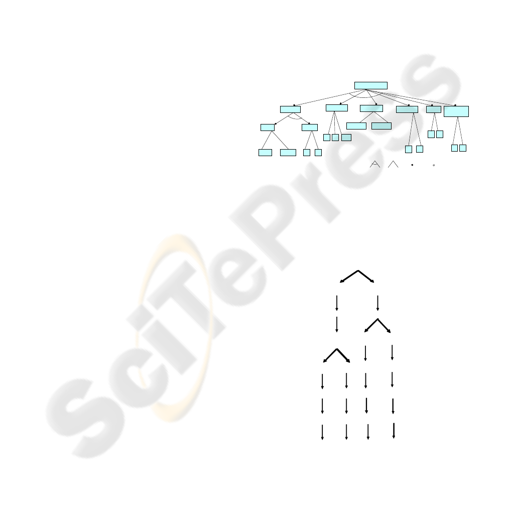
a) The (CIM) Features Model- the Features
Model identifies the DSPL in terms of the
variability in the domain.
DIAGNOSIS
Properties
Reasonings
Hypothesis
same
change
Views
Levels
1 2
1
deductive diferential
Use Cases
1
3
Actors
1 2
Use Cases
by Actor
1 2
NOMENCLATURE:
and
or
(select 1)
mandatory
optional
4 14
Figure 1: The diagnosis features model.
b) The (CIM) Decision Tree- the sources of
variability observed in the Features Model are
shown in the variation points of the Diagnostic
Decision Tree.
change
Reasonings
diferencial
deductiv e
Prop erty Levels
221
Use Cases
Actors
Use Cases by Actor
Hypothesis
1
14
4
2
1
113
1
11
2
11
1
same
1, 2
Property Views
Figure 2: The diagnostic decision tree.
c) The (PIM) Domain Conceptual Model-
this model captures the variability of the
diagnostic domain.
HEALTHINF 2008 - International Conference on Health Informatics
240
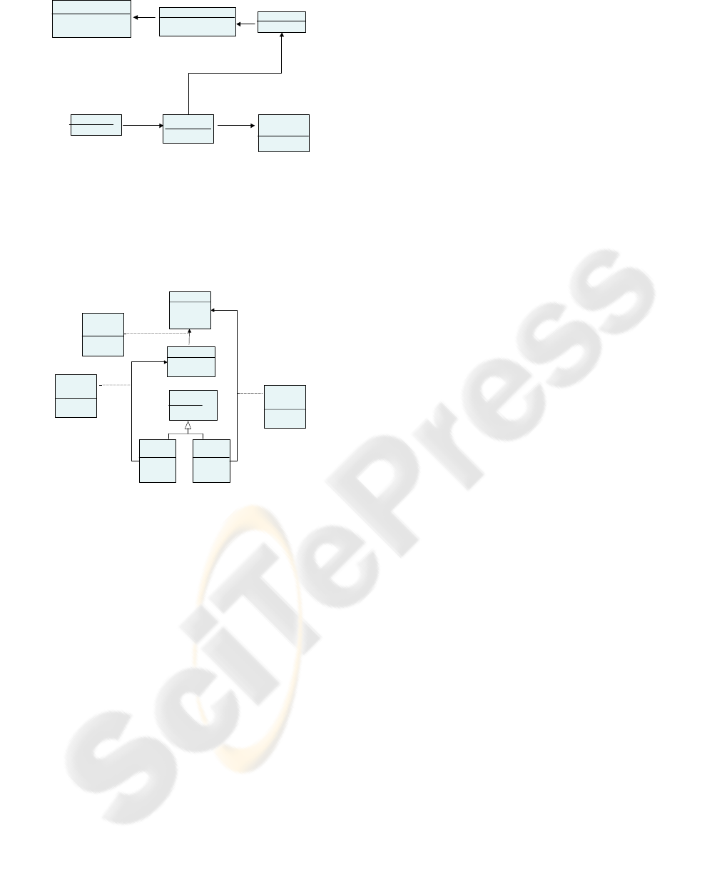
Reasoning
Type: {deductive,
diferential, inductive}
Use Cases
Number : nat
Actors
Number : nat
Use Cases
by Actor
Number : nat
Hypothesis
Number: nat
Entity properties
Type: {same, change}
Levels: nat
is_require
to_perform
is_result
1..* 1
1
1
1..*
1..*
1..*
to_obtain
1
1
to_related
1
1
Figure 3: The domain conceptual model.
d) The (PIM) Application Domain
Conceptual Model- this model captures the
variability of the application domain. (Figure
4 shows the case study of the medical
diagnosis).
Entity properties
Name: string
Type: bool
Level 3
Inductive
Rules
Clause: string
2..*
1
Level 0
Properties
Name:
string
Type: bool
Level 1
Properties
Name:
string
Type: bool
Pre-hypothesis
Name: string
Type: string
Hypothesis
Name: string
Type: string
to_generate
to_validate
to_generate
Level 1
Deductive
Rules
Clause: string
Level 2
Deductive
Rules
Clause: string
1
2..*
2..*
1
Figure 4: An application domain conceptual model.
e) The (PIM) Skeletons or Template Assets-
there are different classes of skeletons or
templates for: components, connectors,
aspects, and interfaces; they follow the
PRISMA Model. The aspects that are
necessary for the definition of these
architectural elements are: the functional
aspects of each one of the components, and
the coordination aspect of the connector.
These aspects use interface services. These
architectural elements are:
• The Inference Motor Component- it
establishes the system’s control and
makes decisions. In addition, the
Inference Motor Component provides the
general resolution strategy to obtain the
diagnosis. It is independent of the system
knowledge. This component has a
functional aspect that defines the
inference process of the system.
• The Knowledge Base Component- it
contains the domain knowledge of the
case study in rules of inference (Horn
clauses) and facts (information that
remains unchanged). This component is a
temporary warehouse of dynamic
information, since the number of facts can
be increased as they relate to the
inference rules of the domain. When a
diagnosis process has concluded, the
contents of the work memory is cleared
so that the memory is empty before
initiating a new diagnosis. The
Knowledge Base Component has a
functional aspect that defines the domain
rules.
• The User Component- it establishes
man-machine interaction by allowing
communication between the users and the
system. Through it, the user offers initial
data to the system or answers questions
formulated by it. This component has a
functional aspect.
• The Diagnostic Connector- this
connector synchronizes or requests
component’s services that are
sent/received through its ports. It has a
coordination aspect. This diagnostic
connector choreographs the diagnostic
process.
f) The (PIM) Features Insertion Process- this
process inserts the features into the software
artefacts. These artefacts represented as XML
documents are transformed using XSLT
templates.
g) The (PIM) RAS Models of the Assets- its
goal is to store information from each one of
the assets: ID asset identifier, asset
classification, description of the different asset
artifacts, variability points of the asset
artifacts.
h) The (PIM) Assets- an asset is composed by
a skeleton, its RAS Model, and its
corresponding insertion process (to be
executed in the application construction
phase).
i) The (PIM) Base-Line- the Base-Line is the
repository that contains all the assets and all
the application domain conceptual models,
which are used to capture the specific
application features.
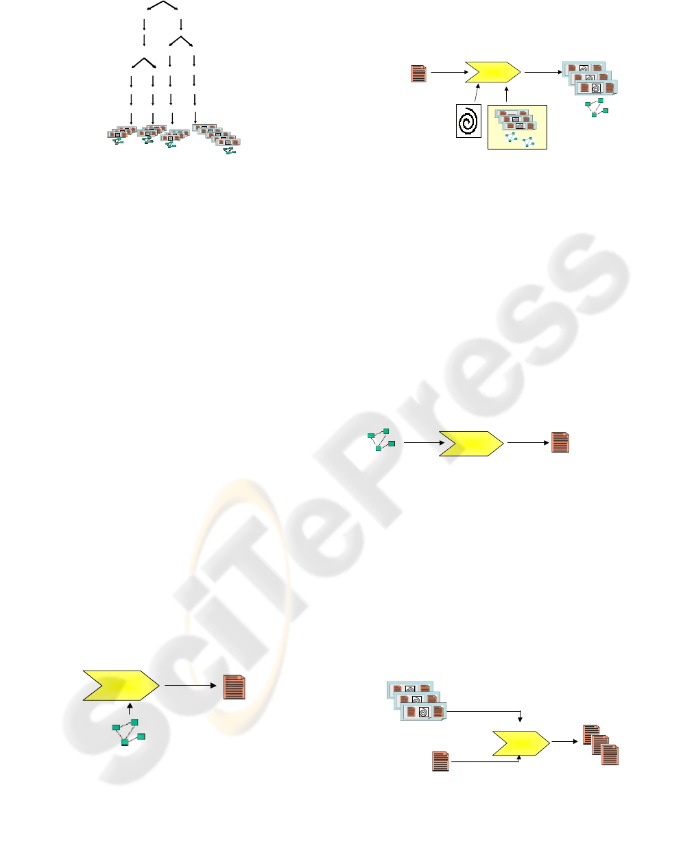
j) The (PIM) Process for selecting the assets
and the application domain conceptual
models- This process computes the paths of
the decision tree, which is used to select the
software artifacts.
A GENERIC SOLUTION FOR THE CONSTRUCTION OF DIAGNOSTIC EXPERT SYSTEMS BASED ON PRODUCT
LINES
241
change
Reasonings
diferencial
deducti v e
Prop erty Levels
221
Use Cases
Actors
Use Cases by Actor
Hypothesis
1
14
4
2
1
113
1
11
2
11
1
same
1, 2
Property Views
Figure 5: Process for selecting the assets and the
application domain conceptual models.
k) The (PIM) Process of the production plan
of our DSPL- this process is described using
the SPEM.
4.2 2
nd
Phase: Application Engineering
The production plan of our Software Product Line is
described using SPEM. The SPEM Metamodel
allows several aspects and problems of the
development process to be modeled. In this work,
we focus on modeling the tasks, using the SPEM
sequence relations without priority. The tasks
performed by the application engineer consume
input artifacts and produce output artifacts. A task
can have associated elements that guide and help in
the task execution.
Each one of these tasks is described below:
Task 1: To create a configuration of the
domain features- The engineer introduces the
domain information of the case study. BOM
captures the variability information by means
of the domain features detailed in the Domain
Conceptual Model. This model allows the
engineer (by means of a GUI) to introduce the
information of the Model by selecting the
product’s features using check boxes and pull-
down menus.
Create configuration
of the domain features
Configuration of the
domain features
(XML)
<<out>>
PIMPIM
<<in>>
Domain Conceptual Model
(UML)
Figure 6: Create a configuration of the domain features.
Task 2: To select Assets and the Application
Domain Conceptual Model.- BOM selects
the assets and the Application Domain
Conceptual Model from the Base-Line (by
means of the decision tree).
PIMPIM
Select assets+MCDA
<<out>>
Base-Line
(XML)
PIMPIM
<<in>>
<<in>>
Process for selecting
Assets+ MCDA
(XML)
<<in>>
Assets (XML)
+
MCDA (UML)
selected
Configuration of the
domain features
(XML)
Figure 7: Select assets and application domain conceptual
model.
Task 3: To create a configuration of the
application domain features.- The engineer
introduces the application domain information
of the case study. BOM captures the
variability information by means of the
application domain features contained in the
Application Domain Conceptual Model. This
model allows the engineer (by means of a
GUI) to introduce the information present in
that Model using check boxes and pull-down
menus.
PIMPIM
Configuration of the
application domain features
(XML)
Create configuration of
application domain features
<<out>>
<<in>>
MCDA selected
(UML)
Figure 8: Create a configuration of the application domain
features.
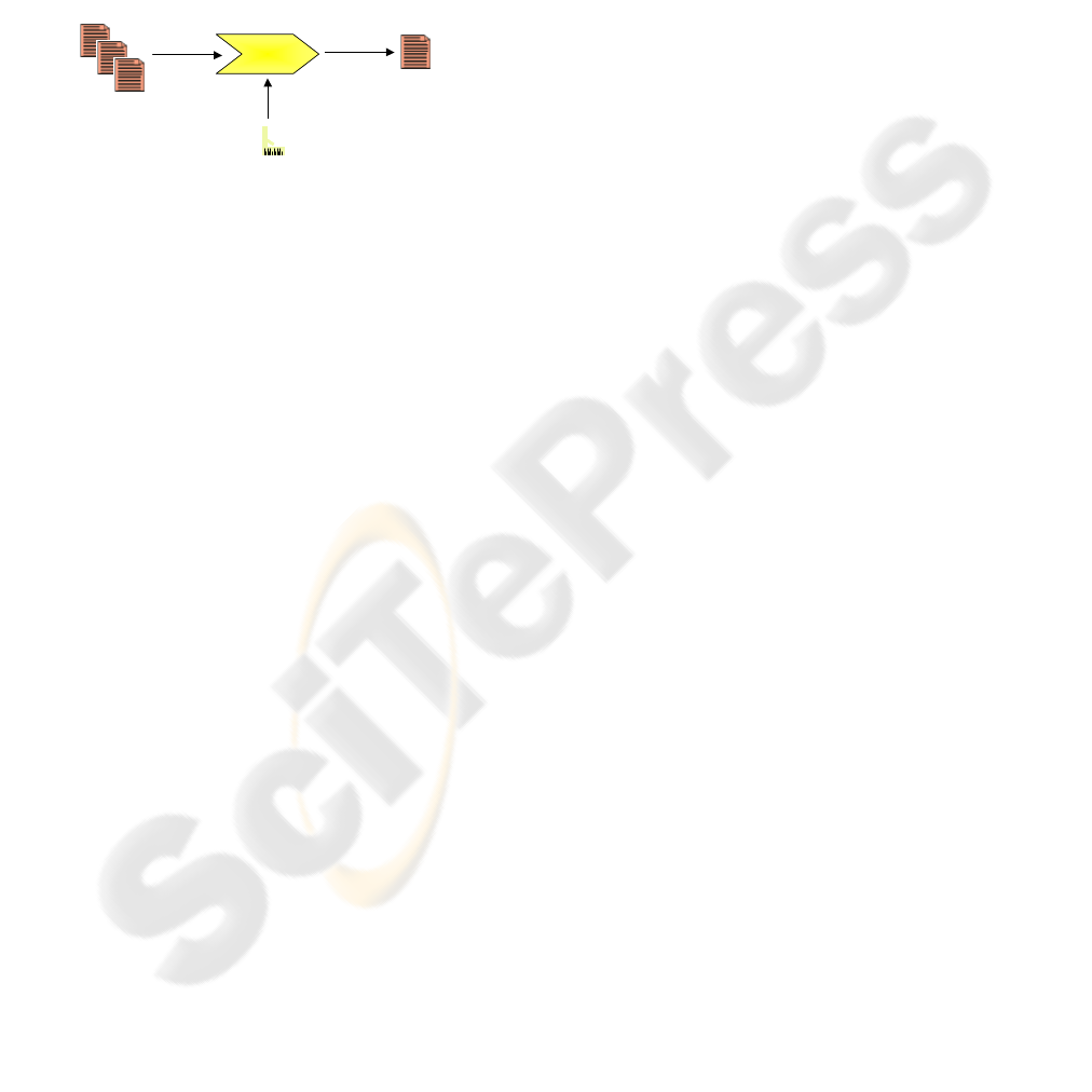
Task 4: To create PRISMA software artifact
types.- BOM fills the selected skeletons with
the data of the specific features of the case
study that were defined by the engineer,
thereby creating the PRISMA software artifact
types. The transformation is represented as
XSLT documents to apply on the XML pages
representing the software artifacts.
PIMPIM
PIMPIM
<<in>>
Types
(XML)
PIMPIM
<<out>>
Create types
<<in>>
Configuration of the
application domain features
(XML)
Assets selected
(XML)
Figure 9: Create PRISMA software artifacts types.
HEALTHINF 2008 - International Conference on Health Informatics
242
Task 5: To configure the Architectural
Model- BOM produces the configuration
program, that is used by the PRISMA-CASE
tool (Cabedo et al., 2005) in order to configure
the PRISMA software architecture by
instancing the PRISMA types. These instances
will configure the software architectures of
our Product Line. Therefore our DSPL are the
diagnosis systems of each one of the specific
domains.
Types
(XML)
<<in>>
Configure architecture
Process to creat
PRISMA architectures
<<in>>
<<out>>
PIMPIM
PIMPIM
Architectural
Model (System
Architecture)
(XML)
Figure 10: Configure the architectural model.
BOM uses the PRISMA-MODEL-COMPILER tool
(Cabedo et al., 2005) to automatically generate the
code (in .NET, C#) of the software architecture of
the preceding task. The final diagnostic system, i.e.
an instance of the DSPL, is executed on top of the
PRISMANET middleware (Costa et al., 2005).
5 THE CASE STUDY
We have selected the field of infantile infectious
diseases as an application domain from the field of
medical diagnosis in order to know the requirements
necessary to obtain the final software product in our
Product Line.
The software system of infantile infectious
diseases contains knowledge that uses a set of rules
made of the signs and symptoms of diseases of the
patient. These signs, symptoms and diseases have
been provided by a paediatrician. The system
proposed in this work, makes the medical diagnosis
by introducing patient data into the system. This data
is made up of sign and symptom values and is input
by the final users of the system. As a result, the
system obtains a diagnosis of the patient’s disease.
The final diagnosis is made from two types of
diagnoses: clinical and laboratory. The objective of
this is to provide a highly accurate diagnosis.
Medical diagnosis is understood as the process
of the identification or recognition of a disease on
the basis of the signs and symptoms (including
laboratory studies) of the patient. The medical
diagnosis represents the research process performed
on the patient, and the diagnosis is based on the
observations and reasoning of the doctor.
In medical diagnosis, the entity to be diagnosed
is the patient, and the result is the disease that a
patient has. The properties are signs and symptoms.
These are classified in two abstraction levels: coarse
grain and fine grain.
The process of medical diagnosis is the
following: A syndrome is inferred from sign and
symptom values of coarse grain. Two or more
possible diseases are inferred from the syndrome.
Deductive reasoning is applied in this part of the
process. These hypotheses must be validated. A
disease (validated hypothesis) is inferred from sign
and symptom values of fine grain. Inductive
reasoning is applied in this part of the process.
We present examples of the properties, rules,
pre-hypotheses and hypotheses of the case study.
properties of level 0: cough, fever
properties of level 1: dry_cough,
constant_fever
pre-hypotheses: warth, parotiditis
hypotheses: pneumonia, bronchitis
rules:
IF (cough=true and fever=true and
respiratory_dificulty=tue)
THEN syndrome=warth
The variability sources or points in the
diagnostic domain of our Product Line for this case
study are the following.
The hypotheses are inferred by means of
different properties of the entities.
The system exhibits a type of behaviour or
reasoning strategy: differential reasoning. This
reasoning strategy is the most widely used in
solving medical diagnostic problems because
it is suited to this kind of task.
The entity properties of level 0 are the signs
and symptoms of coarse grain (e.g. cough and
fever). The entity properties of level 1 are the
signs and symptoms of fine grain (e.g. dry
cough and constant fever).
The pre-hypotheses are syndromes (e.g.
parotiditis) that are inferred by means of rules
of level 1. The hypotheses are the diseases
(e.g. pneumonia) that are inferred by means of
rules of level 2. The diagnostic result is
inferred by means of rules of level 3.
In this case study, several hypotheses are
generated. These must be validated in order to
obtain only one validated hypothesis, which is
the diagnostic result.
The system offers the user the following
functionalities (use cases): clinical diagnosis,
A GENERIC SOLUTION FOR THE CONSTRUCTION OF DIAGNOSTIC EXPERT SYSTEMS BASED ON PRODUCT
LINES
243
laboratory diagnosis, and the visualization of
the results of the final diagnosis.
The use cases are used by two final users
(actors from the use case diagram): doctors or
members of the laboratory. Two use cases can
be invoked by the doctor, and only one use
case can be invoked by a member of the
laboratory. In this case study, there are three
use cases and two actors, where one actor (the
doctor) is associated to two use cases, and the
other actor (the member of the laboratory) is
associated to only one use case. Figure 11
shows the case use diagram for the medical
diagnosis.
Doctor
Member
Laboratory
Get Therapy
Get
Clinical
Diagnostic
Get
Laboratory
Diagnostic
<<
include
>>
Get Diagnostic
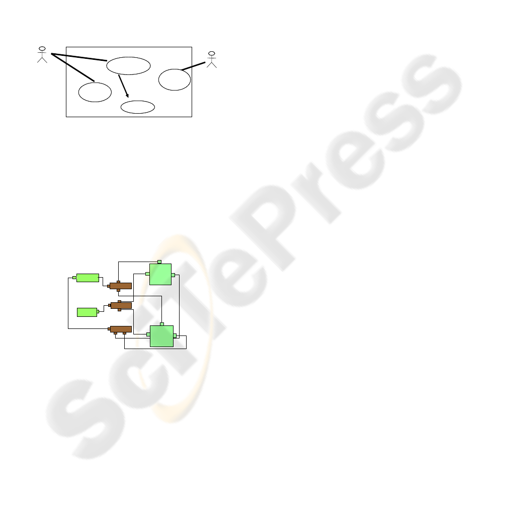
Figure 11: Use case diagram for a medical diagnosis.
The skeletons of the architectural elements are:
Inference Motor (with three ports), Knowledge Base
(with three ports), User Interface 1, i.e., the doctor
(with two ports), User Interface 2, i.e., the member
of laboratory (with one port), Diagnostic Connector
1 (with three ports), Diagnostic Connector 2 (with
three ports), and Diagnostic Connector 3 (with three
ports). The architectural model represents a product
of our DSLP and is shown in Figure 12
CONNEC TOR 2
INFERENC E
MOTOR
IN TER F AC E
US ER 2
CONNEC TOR 1
INTERFACE
US ER 1
CONN ECTO R 3
KNOWLEDGE
BASE
1
3
2
2
2
2
1
1
1
3
2
3
1
2
3
3
1
3
Figure 12: Visual metaphor of the architectural model of
the medical diagnosis system.
We present the (partial) code that is
automatically generated by the PRISMA-CASE tool.
This code corresponds to the Knowledge Base
Component of the case study.
namespace KBMD
{ [Serializable]
public class
KnowledgeBaseMedicalDiagnosis:
ComponentBase
{ public class
KnowledgeBaseMedicalDiagnosis
string name: base (name)
{ AddAspect (new FBaseMD ());
InPorts.Add
(“KnowledgeClinicalPort”,
“IDomainMD”, “KNOWLEDGE_CLIN”);
OutPorts.Add
(“KnowledgeClinicalPort”,
“IDomainMD”, “KNOWLEDGE_CLIN”);
InPorts.Add
(“KnowledgeLaboratoryPort”,
“IDomainMD”, “KNOWLEDGE_LAB”);
OutPorts.Add
(“KnowledgeLaboratoryPort”,
“IDomainMD”, “KNOWLEDGE_LAB”);
InPorts.Add
(“KnowledgeResultsPort”,
“IDomainMD”, “KNOWLEDGE_RES”);
OutPorts.Add
(“KnowledgeResultsPort”,
“IDomainMD”, “KNOWLEDGE_RES”);
} }}
6 RELATED WORKS
There are a great number of works that are related to
our approach. The methodologies and applications
on this subject have produced a wide variety of
research products, offering suggestions and solutions
in specific domains.
A study made by (Liao, 2005) examines the
methodologies of expert systems and classifies them
into eleven categories. Two of these categories
correspond to the systems based on rules and the
systems based on knowledge. These categories have
been taken into account in our work when using
knowledge represented in the form of rules (Horn
clauses) and facts (observable variables). Likewise,
(Liao, 2005) mentions that the applications of the
expert systems are built as specific domain problem
oriented systems. In our work we present a case
study in the medical diagnostic domain.
(Liao, 2005) also mentions that the development
of expert systems has been characterized by the
separation of knowledge and processes as
independent units. In our architectural model, the
elements in the type level are defined taking into
account this concept, specifically when there is a
component that contains the domain knowledge and
another component that executes the inference
process of the diagnosis.
(Giarratano et al., 2004) and other authors in the
field of expert systems considered that the
architectures of these systems are based only on
components. The architecture of our system has
integrated two approaches combining both
HEALTHINF 2008 - International Conference on Health Informatics
244

components and aspects. This increases the
reusability and the maintenance of the system.
Expert systems have also been implemented in
the development of different programming
paradigms such as structured, logic, and object-
oriented paradigms. These paradigms are oriented
toward fourth-generation languages and visual
programming methods to provide user-friendly
communication. PRISMA provides an Architecture
Description Language to define an architectural
model that follows the MDA approach
(http://omg.org.mda), which allows the automatic
generation of code.
The integration of the DSBC and DSOA
approaches are introduced by (Constantinides et al,
2000). The concerns and requirements described in
this work are contemplated in our architectural
model. The advantages of each one of these
approaches are used to define the architectural
elements with their aspects.
MDA proposes the definition of models at high
abstraction level, which are independent of the
technology (PIM). In our work, we have considered
this line of research focusing on experts systems that
are based on product lines.
Our work also applies the detection of the
components based on the functional decomposition
of the problem, which is compatible with the
Architecture Based Design Method (ABD)
methodology (Bachman, 2000). In ABD software
architectures of the application domain are designed.
This methodology has been applied in the building
of our architectural model for medical diagnosis.
The work by (Garlan, 2001) is a very important
reference in establishing the elements of a complex
software system. In his work, he introduces the
component, connector, system, input port, and
output port concepts. These concepts have been
included in our model.
Another work that is related to our approach is
based on the contract concept of (Andrade et al.,
1999). We have defined the connectors of the
architectural models of the DSPL, incorporating the
choreography concept in the connectors, which are
specified by the protocol of the coordination aspect
of the connectors.
There are many Architectural Definition
Languages (ADL), which have advantages and
disadvantages. This study has been done by
(Medvidovic et al., 2000). The language proposed
by (Loques et al., 2000) in their model R-RIO is the
one that is the closed to the PRISMA-ADL. Their
model has re-configuration capabilities like
PRISMA; however their work does not incorporate
the notion of aspect.
Software Product Lines have been an important
discussion topic in the last decade. There are many
works on this subject. Our research is related to the
following works:
(Batory et al., 2006) express the domain
features in the Features Model, and they use
Feature Oriented Programming as a technique
for inserting the features.
(González et al, 2006) applied the MDA
proposal and Requirements Engineering for
Product Lines.
(Clements et al, 2002) use the SPL
development approach, considering a division
between domain engineering and application
engineering for the reuse and the automation
of the software processes.
(Trujillo, 2007) has developed the XAK tool to
insert features into XML documents by means
of XSLT templates.
(Ávila-García et al, 2006) has developed a
MDA tool with functionalities of
metamodeling over MOF and the
transformations in ATC. The authors integrate
the functionalities of the process modeling in
SPEM, and RAS to package reusable assets .
(Santos, 2007) proposes the development of a
technique based on MDA for variability
management in Software Product Lines.
In (ACM, 2006) several works, related with to
the Software Product Line Engineering have
been published.
7 CONCLUSIONS
This paper presents BOM (Base-Line Oriented
Modeling), wich is a framework that automatically
generates diagnostic systems based on software
product lines.
BOM has been designed to improve the
development of diagnostic systems in following
ways:
To use the advantages of Expert Systems:
incorporate several reasoning strategies in
order to solve a problem by applying the most
efficient one, and separate the inference
process of the knowledge information from
the application domain.
To apply techniques from the field Software
Product Lines by building a design that shares
all the members of a program family. In this
way, a specific design can be used in different
products. Since we obtain a specific product
from a series of previous models, the costs,
time, effort, and complexity can be reduced.
A GENERIC SOLUTION FOR THE CONSTRUCTION OF DIAGNOSTIC EXPERT SYSTEMS BASED ON PRODUCT
LINES
245

To construct Product Line Architectures in the
PRISMA framework, is order to have the
advantages of distributed systems, which will
facilitate the management of complexity.
To create an integrated and flexible approach to
describe (medical) diagnosis architectural
models that are complex, distributed, and re-
usable by improving the development of
expert systems for (medical) diagnosis
following the PRISMA model (Pérez, 2006) to
integrate the components and aspects.
To apply MDA techniques to implement the
systems on different platforms, and to
automatically transform them and incorporate
the features of the Features Model instances to
obtain an executable application.
In the future, we want to extended the analysis of
the diagnostic field in other application domains in
order to increase variability and our Base-Line. Our
Products Line will be able to offer more products. In
addition, we plan to validate our approach in other
case studies, and compare the performances of the
generated Expert Systems with other obtained using
other approaches.
ACKNOWLEDGEMENTS
This work has been funded under the Models,
Environments, Transformations, and Applications:
META project TIN20006-15175-605-01.
REFERENCES
Andrade L. and Fiadeiro J., 1999. Interconnecting Objects
via Contracts. OOPSLA´99.
Ávila-García O., García A. E., Rebull V. S., y García J. L.
R., 2006. Integrando modelos de procesos y activos
reutilizables en una herramienta MDA, en XI Jornadas
de Ingeniería de Software y Bases de Datos
JISBD’2006, Barcelona, España.
Bachman F., Bass L., Chastek G., Donohoe P. and
Peruzzi F., 2000. The Architecture Based Design
Method. Technical Report CMU/SEI-2000-TR-001,
Carnegie Mellon University, USA.
Batory D., Benavides D., and Ruiz-Cortés A., 2006.
Automated Analyses of Feature Models: Challenges
Ahead. ACM on Software Product Lines.
Cabedo R., Pérez J., Carsí J.A. y Ramos I., 2005.
“Modelado y Generación de Arquitecturas PRISMA
con DSL Tools”, en Actas del IV Workshop
DYNAMICA, Archena, Murcia, España.
Clements P. and Northrop L.M., 2002. Software Product
Lines: Practices and Patterns. SEI Series in Software
Engineering, Addison Wesley.
Constantinides C.A., and Errad T., 2000. On the
Requeriments for Concurrent Software Architectures
to Support Advanced Separation of Concerns. In
Proceedings of The OOPSLA 2000, Workshop on
Advanced Separation of Concerns in Object-Oriented
Systems.
Costa C., Pérez J., Ali N., Carsí J.A. y Ramos I., 2005.
“PRISMANET: Middleware: Soporte a la Evolución
Dinámica de Arquitecturas Software Orientadas a
Aspectos”, en Actas de las X Jornadas de Ingeniería
del Software y Bases de Datos, Granada, España.
Czarnecki K., and Eisenecker U., 2000. Generative
Programming: Methods, Tools, and Applications.
Addisson-Wesley. ISBN 0-201-30977-7.
Garlan D., Cheng S. and Kompanek A. J., 2001.
Reconciling the Needs of Architectural Description
with Object Modeling Notations. Science of Computer
Programming Journal, Special UML Edition, Elsevier
Science.
Giarratano, J., and Riley, G., 2004. Expert Systems:
Principles and Programming. Fourth Edition:
(Hardcover), ISBN: 0534384471.
González-Baixauli B. y Laguna M. A., 2005. MDA e
Ingeniería de Requisitos para Líneas de Producto.
Taller sobre Desarrollo Dirigido por Modelos. MDA y
Aplicaciones. (DSDM´05), Granada, España.
Greenfield J., Short K., Cook S, Kent S., and Crupi J.,
20004. Software Factories: Assembling Applications
with Patterns, Models, Frameworks, and Tools. Wiley.
Liao S.-H., 20005. “Expert Systems Methodologies and
Applications- a Decade Review from 1995-2004”, in
Expert Systems with Applications, Vol. 28, Issue 1.
Loques O., Sztajnberg A., Leite J., and Lobosco M., 2000.
On the Integration of Meta-level Programming and
Configuration Programming. In Reflextion and
Software Engineering (special edition), Lectures
Notes in Computer Science, Springer-Verlag,
Heidelberg, Germany
Medvidovic N., and Taylor R.N., 2002. A Classification
and Comparison Framework for Software
Architecture, in Proceedings of IDEAS, Cuba.
Pérez J., 2006. PRISMA: Aspect-Oriented Software
Architectures. PhD. Thesis of Philosophy in Computer
Science, Polytechnic University of Valencia, Spain.
Santos A.L., Koskimies K., and Lopes A., 2005. Using
Model-Driven Architecture for Variability
Management in Software Product Lines. Ph Thesis
Proposal Facultade de Ciencias de la Universidade de
Lisboa, Portugal.
Software Product Line Engineering Communications of
the ACM. 2006, Vol 49, Number 12, pp 28-88.
Szyperski C., 1998. “Component software: beyond object-
oriented programming”, ACM Press and Addison
Wesley, New York, USA.
Trujillo S., 2007. Feature Oriented Model Driven Product
Lines. PhD. Thesis, The University of the Basque
Country, San Sebastian, Spain.
HEALTHINF 2008 - International Conference on Health Informatics
246
