
A SIMPLE DEVICE TO MEASURE GAZE ANGLES IN VISUAL
TASK ANALYSES
A. Page, B. Mateo, J. Garrido-Jaén, R. Marzo
Instituto de Biomecánica de Valencia, Universidad Politécnica de Valencia, Camino de Vera s/n, 46022 Valencia, Spain
J. C. Dürsteler, A. Giménez, C. Prieto
Indústrias de Óptica, S.A. (INDO). Alcalde Barnils, 72. 08174 Sant Cugat del Vallès, Barcelona, Spain
Keywords: Optometry, Visual strategy, Head Movements, Eye tracking, Progressive Addition Lenses.
Abstract: This paper presents a simple device to measure visual maps and head motion to analyze the visual strategy
in optometric applications. Instead of using the common approach of conventional eye trackers based on
continuous pupil–corneal reflection detection, a simple method based on photogrammetry is proposed. This
method only measures the head movements, the gaze direction and the visual map can be calculated on the
hypothesis that subjects’ gaze follows a known visual stimulus accurately.
In order to validate this hypothesis, an experiment has been carried out to calculate the subject’s accuracy
when tracking the stimulus. The gaze direction was measured both with conventional eye tracking and with
the proposed technique and the measured gaze angles were compared. The results show that the subjects
effectively follow the stimulus during the task and thus the main hypothesis of the proposed system is
confirmed. Therefore, the analysis of head movement can supply an indirect estimation of the visual angles
that is as accurate as the measures obtained with more complex devices.
1 INTRODUCTION
Visual strategy can be defined as the coordination of
eyes and head movements in order to perform a
visual task. The study of visual strategy has received
some interest from fields as diverse as neuroscience
and psychophysics, customer behaviour analysis and
advertising, ergonomics, sports or lenses design and
optometry.
Techniques of eye-tracking have been used for a
long time in the fields of psychophysics and
neuroscience. Richardson and Spivey have
published a complete survey about the main research
areas in these fields (Richardson and Spivey, 2004
a
;
Richardson and Spivey, 2004
b
). The analysis of
visual strategies can also provide information about
the consumer behaviour and thus help to identify
factors that determine the attention allocated to
different advertisements (Treistman and Gregg,
1979; Lohse, 1997).
In the ergonomics scope, research on visual
strategy is mainly focused on the study of the visual
demands of different tasks in order to improve the
workplace design and task performance (Engström
et al. 2005). Other applications are related to the
design of technical aids for disabled people, such as
control systems based on eye-gaze tracking (Sesin et
al. 2003). The visual strategy is particularly
important in the study of some complex tasks in
sports such as ball sports or boxing, in which a
player needs to determine the future trajectory of the
ball (or hand). Thus, several studies have been
carried out to analyze the influence of visual strategy
on the subject skills (Ripoll et al. 1995; Land and
McLeod, 2000).
The use of eye movement analysis in the field of
optometry is more recent and its applications seem
promising. Monitoring visual performance can help
to quantify the state of the ocular motor system and
provide valuable diagnosis and management support
(Abadi, 2006). Besides, visual strategies analyses are
the basis of some aspects of corrective lenses design,
especially to assess the comfort of progressive
addition lenses (PALs) wearers. Some studies in this
field have been performed to understand the
differences of users’ behaviour when using different
119
Page A., Mateo B., Garrido-Jaén J., Marzo R., C. Dürsteler J., Prieto C. and Giménez A. (2008).
A SIMPLE DEVICE TO MEASURE GAZE ANGLES IN VISUAL TASK ANALYSES.
In Proceedings of the First International Conference on Biomedical Electronics and Devices, pages 119-125
DOI: 10.5220/0001046501190125
Copyright
c
SciTePress

PAL designs or single vision lenses (Selenow et al.
2002; Han et al. 2003; Hutchings et al. 2007).
Several techniques have been used for measuring
eye movement as well as for characterizing visual
strategies. Morimoto and Mimica (Morimoto and
Mimica, 2005) present a good survey of techniques
for eyes gaze tracking. The most widely used are
based on the automatic detection of the pupil-corneal
reflection. The eye is illuminated by a distant, low-
power, infra-red light source, and this creates an
image that is seen as a highlight spot on the surface
of the cornea. The image is analysed by a computer,
which calculates the centre of the corneal reflection
as well as the centre of the pupil. The distance from
the pupil centre to the corneal reflection is
proportional to eye rotation, and thereby provides an
estimation of the gaze direction. Since the eye
position varies as the head moves, the head should
remain still during the measurement; otherwise the
movement of the head must be measured in order to
transform the relative direction of gaze into absolute
directions to the visual targets.
Then, a complete description of visual strategy
needs both gaze direction and head position analysis.
Head motion can be accurately measured in real-
time by means of a magnetic location system
(Hutchings et al. 2007), although these systems are
intrusive because a device must be placed on the
subject head. There have been some recent attempts
to avoid such kind of devices by measuring head
movements by means of a 3D face tracking analysis,
as proposed in (Beymer and Flickner, 2003).
The systems based on pupil-corneal reflection
need some type of calibration to transform the input
data (reflections’ locations) into absolute gaze
directions. A typical calibration procedure presents
the user a set of visual targets that the user has to
look at while the corresponding measurement is
taken. From these measurements a map of
correspondences or calibration function can be
obtained. Although several models to calibrate the
eye tracker systems have been developed, the
calibration process is one of the worst problems in
current commercial systems. On the one hand, the
calibration functions are very sensitive to head
motion, which is the cause of the main source of
inaccuracy. On the other hand, calibration is a
troublesome process that demands controlled
environmental conditions. For these reasons some
tracking systems are difficult to use and inadequate
for applications outside a research laboratory
(Schnipke and Todd, 2000).
A strategy to improve the accuracy and
simplicity of the systems is to adapt them to specific
functions, so that only the precise information is
measured in the simplest way. For example, some
clinical and optometric applications are focused on
the ocular motor performance when the subject
performs a specific task with well-known stimuli
(Abadi, 2006). This way, the measurement of the
absolute gaze direction is unnecessary and the
measurement of head movements and relative eyes
motion is enough.
The objective of this paper is to describe and
validate a new device to measure the relative motion
of eyes with the aim of obtaining visual maps. This
information could be useful to analyze differences of
visual strategies in the design of progressive addition
lenses. The device uses video-photogrammetry
techniques and it is based on the assumption that
only head motion measurement is necessary to
estimate eye gaze direction when the target position
is known.
In order to validate this proposed technique, an
experimental study has been performed in which the
subject accuracy when tracking a visual stimulus is
calculated. The measures obtained with our device
were compared with those a conventional eye
tracker. The results show that the measurement of
head movement can supply an indirect estimation of
the visual angles when the tracked target locations
are known and the results are as accurate as the
measures obtained with more complex devices.
2 MATERIALS AND METHODS
2.1 General Description of the
Equipment
The principle of operation of the proposed technique
assumes that a subject can effectively gaze at a
mobile target, so that eye gaze direction in relation
to the head is determined by knowing both target
and head positions, as well as the relative location of
eyes with respect to head.
The measurement system consists of a 650 x 500
mm dark screen, which shows a 1 cm illuminated
spot that moves along a continuous trajectory. At
both sides of the screen, two synchronised video
cameras record the subject’s head motion. Cameras
have a 640 X 480-pixel resolution with a 25 fps
recording speed. The cameras are equipped with
infrared filtersCameras have been previously
calibrated using the DLT algorithm (Abdel-Aziz and
Karara, 1971) and lenses distortion corrected by
means of the procedure described in (Ahmed and
BIODEVICES 2008 - International Conference on Biomedical Electronics and Devices
120
Farag, 2005). Therefore, it is possible to accurately
measure head position and motion. This analysis can
be made from the coordinates of some face
distinctive points, using well-known image analysis
protocols as the Harris corner detector (Hartley,
2004). However, in order to simplify the
computations and to allow a real-time analysis, no
computational expensive image processing has been
used. Thus, the position and motion of head are
measured by means of a set of active makers. The
markers cluster consists of four infrared leds placed
on a diadem that adjusts at the head.
Besides, the system has an infrared light source
placed in the middle of the screen to create a corneal
reflection that allows detecting eyes’ position during
the calibration step.
2.2 Measurement Process
The measurement process is performed in two steps:
first the measurement of an initial reference position,
and then the measurement phase, where visual angle
is recorded during the performance of a tracking
visual task. In the first step, the subject sits 50 cm in
front of the screen. He is asked to adopt a neutral
head posture with the gaze direction approximately
horizontal. This position is considered as the
reference posture. Then measurement system detects
the markers’ positions and places the target in the
middle of the screen at approximately the eyes
height. Eyes positions are detected by the corneal
reflection produced by infrared light source. The
corneal reflection 3D position is automatically
measured. Thus, eyes centre position is calculated
assuming a spherical shape of the cornea with
known radius.
Simultaneously, markers’ positions are
determined and a local reference system linked to
the subject’s face is defined. The X axis is traced
from left to right eyes. The local coordinate’s origin
O is placed in the middle point between the eyes.
The Z axis is the most vertical axis belonging to the
plane perpendicular to X axis which pass throughout
O. Finally, the Y axis is defined to make the
reference system right-handed.
Therefore, right eye coordinates in the local
system are [d/2, 0, 0], where d is the subject’s
interpupilar distance.
Detection of corneal reflection is necessary only
at the first step. Once eyes relative positions with
respect to the diadem are identified, their position in
space can be determined from the head motion, and
no more check up is necessary. This fact avoids
having to perform high computational cost image
processing tasks and allows free head movements.
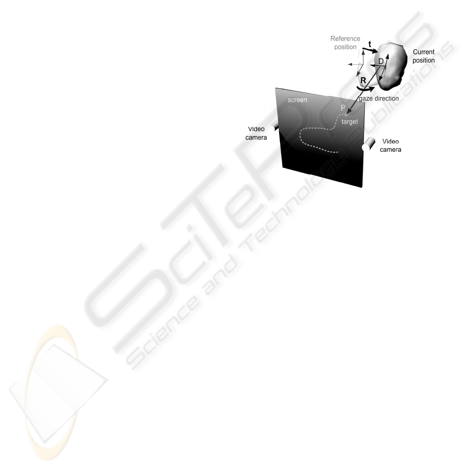
Figure 1 shows the equipment operating scheme
during a tracking test of a moving target. At each
instant, the target is located on the screen at a known
position, P. The subject has moved his head from the
reference position to a different one. This movement
is defined by translation t of the local reference
system and by the rotation matrix R in relation to the
initial reference position. Using t and R, the eyes’
current positions are determined. Specifically, right
eye will be placed at point D.
Figure 1: Equipment operating scheme.The subject looks
at a mobile target P on the screen. Head position and
motion are measured by means of two synchronized
videocameras. Gaze direction is estimated from head
position, location of P and the relative position of eyes in
the head.
C
alculation of head position and movement is
performed in real time from the diadem’s markers’
coordinates by using the algorithm described in
(Woltring et al., 1994). This algorithm allows
obtaining rotation matrix R and translation vector
tAssuming that a person tracks the target, actual
gaze direction is given by vector DP (Figure 1)
which can be calculated in the absolute reference
system. If this vector is expressed in the local
reference system, then the horizontal angle is
calculated as the angle that forms the DP projection
on the Z=0 plane with the local axis Y, whereas the
vertical angle is the one formed by DP line with the
Z=0 plane.
2.3 Equipment Accuracy Random
Instrumental Errors
The measurement of vision angles has two main
sources of error. First, the instrumental errors
A SIMPLE DEVICE TO MEASURE GAZE ANGLES IN VISUAL TASK ANALYSES
121
associated to 3D reconstruction process and head
movement measurement. Second, the error due to
the subject’s gaze deviation when tracking the
target. The latter error is studied in the experiment
described below, so this section focuses on
instrumental accuracy only.
Measurement errors of the markers’ coordinates
depend on camera resolution, accuracy of the marker
centroid determination, and separation between the
cameras (Hartley, 2004). In our system, focal
distance is close to 1000 pixels, measurement
centroids accuracy is estimated to be 0.3 pixel and
photogrammetric system baseline is b = 650 mm.
This configuration provides instrumental
coordinates’ error of around 0.1 mm in X and Z
coordinates and close to 0.2 mm in Y direction.
Angular and position errors associated to this
coordinates’ error estimation can be calculated by
means of the procedure described in (Page et al.,
2006). For the diadem geometry (four markers in a
15 x 15 cm squared), these errors are about 0.1º.
Linear displacement error is less than 0.1 mm. The
worst accuracy appears in the location of the eyes
centres, where a well-known corneal radius is
assumed. Then, an error of around 1 mm can be
expected. Nevertheless, this error has little effect on
the gaze angle estimation, because of the great
distance between subject and screen. So, if this
distance is 500 mm, the systematic angle error is less
than 0.1º for a gaze angle of 20º. Note that a correct
estimation of corneal radius is critical in
conventional tracking systems, because angle
direction computation depends upon this measure.
In summary, random instrumental errors
associated to photogrammetic techniques are really
small and they are negligible in relation with subject
performance errors due to the subject’s gaze
deviation when tracking the target. This source of
error is studied at the following section.
3 VALIDATION
The device operates on the hypothesis that subjects’
gaze follows the target accurately. Consequently, it
is possible to calculate the relative gaze direction
from the target location and the head movements.
Therefore, the validation consisted on evaluating the
subject’s gaze deviation from the target in a tracking
visual task. In order to do it, the measures obtained
with the proposed devices were compared with the
ones provided by a commercial eye tracker.
Two visual tasks were performed. The first had
to aim to estimate the accuracy of the conventional
eye tracker. The second consisted on a dynamic task,
tracking a moving target, with the aim to quantify
the deviation of gaze direction with respect to the
actual target location.
Five subjects participated in these experiments.
3.1 Equipment
Eye and head movements were recorded during the
tasks using a head mounted eye-tracker (Model 501,
ASL Applied Science Laboratories) integrated with
a head-tracker, 3SPACE FASTRAK (Polhemus,
Colchester, VT 05446, USA).
The eye-tracker measures the angle of gaze with
respect to a calibrated scene in the horizontal and
vertical directions. The accuracy reported in the
equipment specifications is less than 1 degree and
may increase to 2 degrees in the periphery of the
visual field.
3.2 Experimental Procedure
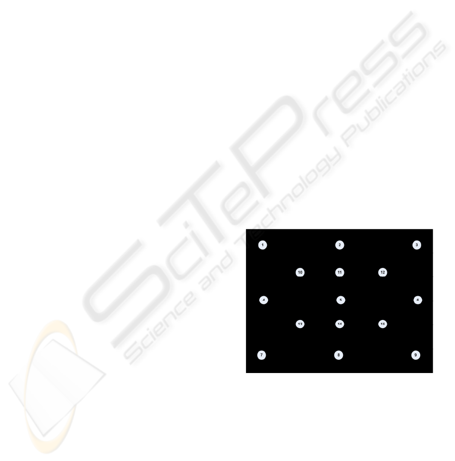
The visual tasks were displayed on a 19 inches
computer screen. Subjects sat in front of the screen.
The distance between monitor and subjects was 50
cm. The monitor height varied depending on the
subject to obtain a zero vertical gaze angle when
looking at the centre of the screen, point 5 in the
calibration scene (Figure 2).
Figure 2: Calibration Scene.
Previous to performing the tasks a calibration
process was completed for each user. This
calibration consisted on looking at 17 target points
located at known positions. During this process the
eye tracker records the corneal reflection of the left
eye as well as the pupil and head movements.
Once the calibration was carried out, the subjects
performed two visual tasks. In the first task (static
task) the subjects looked consecutively at each one
to 17 target points of the calibration scene during
BIODEVICES 2008 - International Conference on Biomedical Electronics and Devices
122
three seconds while the eye and head position were
registered.In the second task (tracking task) subjects
were asked to follow with their eyes a moving target
onto the 19’’ black screen. The target was a red spot
moving with a pseudo-random trajectory on the
screen during two minutes. The trajectory consisted
on a set of concentric circles and radial lines from
the centre of the screen with a randomized sequence
(see figure 3). The velocity of the point motion was
7 cm/sec (8º/sec gaze angle, approximately). This
velocity is similar to the one used to measure the
visual maps.
4 RESULTS
The data registered in the static task was used to
estimate the accuracy of the eye tracker system as
the deviation between the gaze lines and the
measured ones by means the eye-tracker.
For each subject, the accuracy of the eye tracker
system was quantified as the standard deviation in
degrees of the horizontal and vertical eye angle
differences between actual and measures lines while
performing this static task (Table 1)
Results show that the standard deviations of
errors are smaller than 1º in all subjects for
horizontal angles, and a bit greater in vertical angle
measurements. Mean values of these errors are
smaller than 1º. Thus, the calibrated eye tracker
fulfils the accuracy specified by the manufacturer.
The eye angular deviation when executing the
tracking task was obtained in a similar way. At each
time, the theoretical eye line of gaze corresponding
to the moving target was calculated and it was
compared with actual gaze line measured by the eye-
tracker. Vertical and horizontal angle deviations
were analyzed.
Table 1: Errors in the static task. These errors quantify the
accuracy of the reference conventional eye-tracker.
System Error (standard deviation)
Subject Horizontal (º) Vertical (º)
s1 0.42 0.58
s2 0.51 0.53
s3 0.95 1.52
s4 0.67 0.47
s5 0.57 0.84
Mean 0.65 0.88
Table 2: Errors of the horizontal and vertical angles for the
dynamic tracking task.
Tracking error (standard deviation)
Subject Horizontal (º) Vertical (º)
s1 0.53 0.48
s2 0.49 0.61
s3 0.49 0.59
s4 0.56 0.77
s5 0.61 0.70
Mean 0.54 0.64
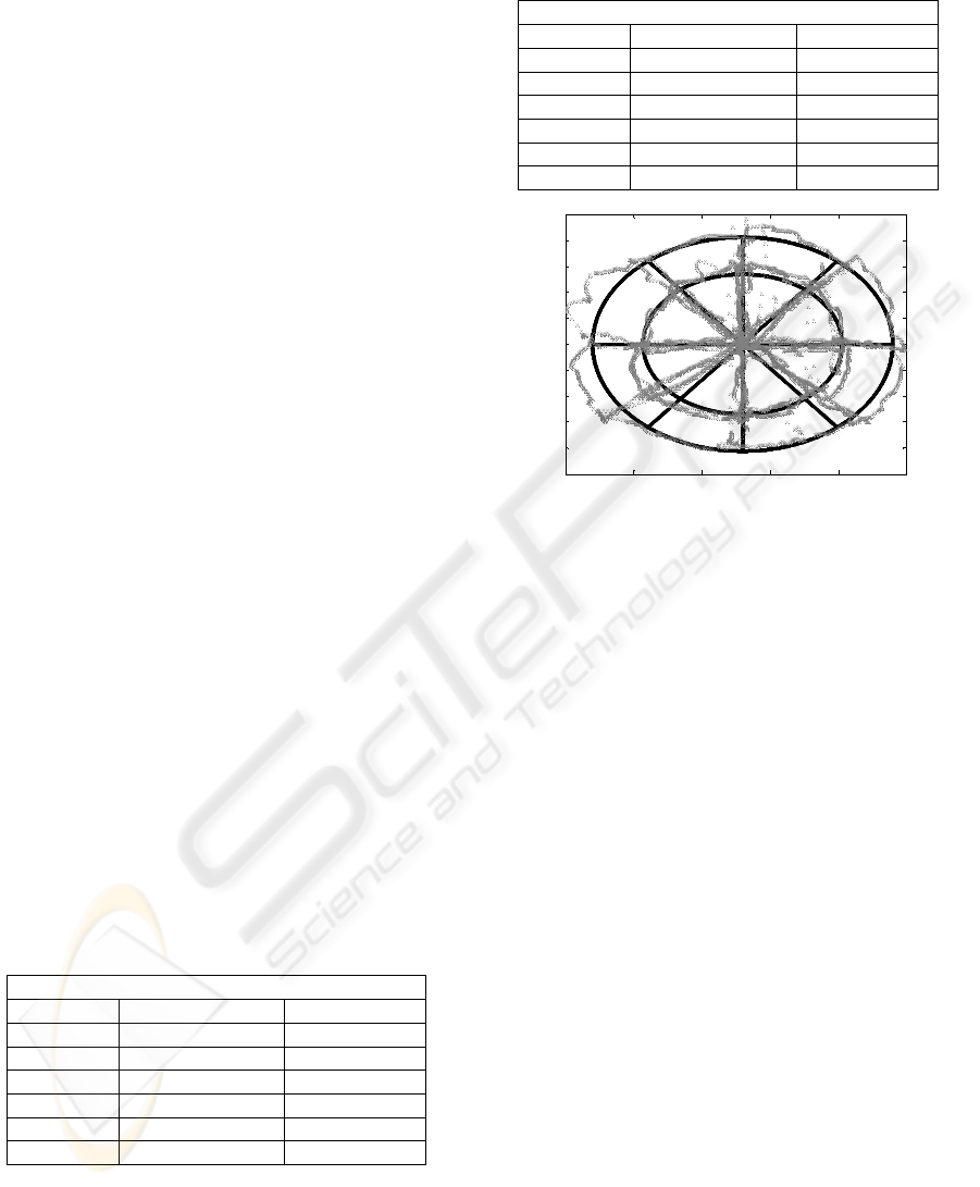
0 50 100 150 200 250
20
40
60
80
100
120
140
160
180
200
220
Figure 3: Deviations in tracking task. Black solid line is
the trajectory of the target on the screen. Grey markers
represent the actual gaze direction.
Figure 3 shows an example of the results in an
individual dynamic task. The black solid line
represents the actual trajectory of the moving target
on the screen. The grey markers represent the
intersection of measured gaze line with the screen.
This way, the distances between the actual target
location and the one obtained from the measured
gaze line quantifies the gaze error when executing
the task. These distances were normalized as angles
(by means of the distance to the screen). The
“accuracy” of the tracking task was quantified by the
standard deviation of the measured angular
deviations for both vertical and horizontal angles.
Table 2 shows the errors for each user as well as
the mean of the sample. The errors are smaller than
1º in all cases, both for vertical and horizontal
angles. In fact the order of magnitude is the same as
the accuracy of the conventional eye-tracker in static
calibrated tasks.
Note that the errors measured in the dynamic
task have two sources of variance. First, we can
expect some instrumental error associated to the
accuracy of the eye-tracker device. This error can be
estimated by the results obtained in the static task
and is quantified in Table 1. Second, the dynamic
errors depend on the subjects’ ability to effectively
follow the moving target. The errors described in
table 2 are the associated to both sources.
A SIMPLE DEVICE TO MEASURE GAZE ANGLES IN VISUAL TASK ANALYSES
123

By comparing the magnitude of static errors (Table
1) and total errors (Table 2), we can see that these
errors are similar. Thus, the mean errors in the static
tasks are around 0.65º for horizontal angles and
around 0.88º for the vertical ones. The errors
estimated in the tracking tasks were similar (0.54º
and 0.64º, respectively). We can conclude that the
subjects effectively follow the moving target during
the experiments, in any case within the margin of
accuracy of a conventional eye-tracker.
Therefore, the main hypothesis of operation of
the proposed system is confirmed: it is possible to
measure the relative gaze angles from the
movements of the head if the location and motion of
the target is known.
5 CONCLUSIONS
AND DISCUSSION
Despite the extensive development of the eye
tracking techniques, the available commercial
devices present some problems, mainly related with
a robust recognition of eye characteristics, their
sensitivity to head movements and the necessity of
previous calibrations. All these factors have
influence on the devices’ accuracy as well as on the
reliability and feasibility of their use in poorly
controlled environments.
However, some specific applications in the filed
of optometry use only specific information about
gaze lines that do not need complex equipment. This
is the case of the visual maps measurement, an
application of eye-tracking techniques to analyze the
user response to progressive addition lenses. In these
applications, the use of specifics technologies could
avoid the drawbacks of conventional equipments.
In this paper we propose an effective and simple
technique for the accurate measurement of the
relative gaze angles while executing visual tasks.
The system operates on a simple principle: the use of
a visual target with controlled location and the
measurement of head movements. Determining once
the location of the subject’s eyes in a reference
posture, the estimation of gaze direction is feasible
just with head movement measurement.
The use photogrammetric techniques allows a
very accurate measurement of these movements,
with an instrumental error lower than 0.5º. However,
the system reliability depends on the subjects’
effectiveness on tracking the target.
The experimental validation with subjects
demonstrated accurate target tracking, with an error
below the accuracy of the conventional eye-tracker
used in the experimentation.
Therefore, the proposed technique permits a
simple and robust measurement of the visual maps,
with the same accuracy as the measure performed
with a complex and expensive equipment.
ACKNOWLEDGEMENTS
This research has been partially supported by the
Spanish Ministry of Science and Education Grant
DPI2006-14722-C02-01 (A. Page).
REFERENCES
Abadi, R.V. 2006. Vision and eye movements. Clinical
and Experimental-Optometry, 89, 2, pp 55-56
Abdel-Aziz, Y. I. and Karara, H. M., 1971. Direct linear
transformation from comparator coordinates into
object-space coordinates, in Proceedings ASP/UI
Symposium on Close-Range Photogrammetry
(American Society of Photogrammetry, Falls Church,
VA) pp 1-18
Ahmed, M. and Farag, A., 2005. Nonmetric Calibration of
Camera Lens Distortion: Differential Method and
Robust Estimation. IEEE Transactions on Image
Processing, 14, 8, pp 1215-1230
Beymer, D. and Flickner, M., 2003. Eye gaze tracking
using an active stereo head, in: Proc. of the IEEE
Conference on Computer Vision and Pattern
Recognition, II, Madison, WI, pp. 451–458
Engström, J., Johansson, E. and Östlund, J., 2005. Effects
of visual and cognitive load in real and simulated
motorway driving. Transportation Research: Part F, 8,
pp 97-12
Han, Y., Ciuffreda, K. J., Selenow, A. and Ali, S. R.,
2003. Dynamic interactions of eye and head
movements when reading with single-vision and
progressive lenses in a simulated computer-based
environment. Invest. Ophthalmol. Vis. Sci. 44, pp 1534–
1545
Hartley, R. and Zisserman, A., 2004. “Multiple View
Geometry in Computer Vision”. Cambridge
University Press.
Hutchings, N., Irving, E., Jung, N., Dowling, L. and
Wells, K., 2007. Eye and head movement alterations
in naïve progressive addition lens wearers. Ophthal.
Physiol. Opt., 27, pp 142–153
Land, M.F. and McLeod,,P., 2000. From the eye to
actions: how batsmen hit the ball. Nature
Neuroscience, 3, pp 1340-1345
Lohse, G.L., 1997. Consumer eye movement patterns on
Yellow Pages advertising, Journal of Advertising. 26,
1, pp 61-73
BIODEVICES 2008 - International Conference on Biomedical Electronics and Devices
124

Morimoto, C.H. and Mimica, M.R.M., 2005. Eye gaze
tracking techniques for interactive applications.
Computer Vision and Image Understanding 98, pp 4–24
Page, A., De Rosario, H., Mata, V., Hoyos, J. and Porcar,
R., 2006. Effect of marker cluster design on the
accuracy of human movement analysis using
stereophotogrammetry. Med Biol Eng Comput. 44, pp
1113-1120
Richardson, D.C. and Spivey, M., 2004a. Eye tracking:
Characteristics and methods. In G. Wnek & G. Bowlin
(Eds.) Encyclopedia of Biomaterials and Biomedical
Engineering, pp.568-572. New York: Marcel Dekker, Inc.
Richardson, D.C. and Spivey, M., 2004b. Eye tracking:
Research areas and applications. In G. Wnek & G.
Bowlin (Eds.) Encyclopedia of Biomaterials and
Biomedical Engineering, pp. 573-582. New York:
Marcel Dekker, Inc.
Ripoll, H., Kerlirzin, Y., Stein, J. and Reine, B., 1995.
Analysis of information processing, decision making,
and visual strategies in complex problem solving sport
situations. Human Movement Science, 14, pp 325-349
Selenow, A., Bauer, E. A., Ali, S. R., Spencer, L. W. and
Ciuffreda, K. J., 2002. Assessing visual performance
with progressive addition lenses. Optom. Vis. Sci. 79,
pp 502–505
Sesin, A., Adjouadi, M. and Ayala, M., 2003. A
calibrated, real-time eye gaze tracking system as an
assistive system for persons with motor disability. 7th
world multiconference on systemics, cybernetics and
informatics, VI, proceedings, pp 399-404
Schnipke, S.K. and Todd, M.W., 2000. Trials and
tribulations of using an eye-tracking system, in: Proc.
ACM SIGCHI—Human Factors in Computing
Systems Conference, pp. 273–274
Treistman, J. and Gregg, J. P., 1979. Visual, verbal, and
sales responses to print ads. Journal of Advertising
Research, 19, 4, pp 41-44
Woltring, H.J., Long, K., Osterbauer, P.J. and Fuhr, A.W.,
1994. Instantaneous helical axis estimation from 3-D
video data in neck kinematics for whiplash
diagnostics. Journal of Biomechanics, 27, 12, pp 1415-
1432
A SIMPLE DEVICE TO MEASURE GAZE ANGLES IN VISUAL TASK ANALYSES
125
