
NEW DEVELOPMENT ON SHAPE MEMORY ALLOYS
ACTUATORS
Roberto Romano
Instituto de Pesquisas Tecnológicas do Estado de São Paulo and Telecommunications and Control Department
Escola Politécnica da Universidade de São Paulo, São Paulo, Brazil
Eduardo Aoun Tannuri
Instituto de Pesquisas Tecnológicas do Estado de São Paulo and Mechatronics Engineering Department
Escola Politécnica da Universidade de São Paulo, São Paulo, Brazil
Keywords: Modeling, shape memory alloy, actuator, robotics, sliding mode control.
Abstract: The present paper presents the development of a mechanical actuator using a shape memory alloy with a
novel cooling system based on the thermo-electric effect (Seebeck-Peltier effect). Such a method has the
advantage of reduced weight and requires a simpler control strategy as compared to other forced cooling
systems. A complete mathematical model of the actuator was derived, and an experimental prototype was
implemented. Several experiments are used to validate the model and to identify all parameters. A robust
and nonlinear controller, based on sliding-mode theory, was derived and implemented. Experiments were
used to evaluate the actuator closed-loop performance, stability, and robustness properties. The results
showed that the proposed cooling system is able to improve the dynamic response of the actuator.
1 INTRODUCTION
Shape Memory Alloys (SMAs) consist of a group of
metallic materials that demonstrate the ability to
return to some previously defined shape or size
when subjected to the appropriate thermal
procedure. The shape memory effect occurs due to a
temperature and stress dependent shift in the
materials crystalline structure between two different
phases called Martensite and Austenite. Martensite,
the low temperature phase, is relatively soft whereas
Austenite, the high temperature phase, is relatively
hard. The change that occurs within SMAs
crystalline structure is not a thermodynamically
reversible process and results in temperature
hysteresis. SMAs have been used in a variety of
actuation applications. The key feature of this
material is its ability to undergo large seemingly
strains and subsequently recover these strains when
a load is removed or the material is heated. SMA
actuators have several advantages such as excellent
power to mass ratio, maintainability, reliability, and
clean and silent actuation. The disadvantages are
low energy efficiency due to conversion of heat to
mechanical energy, inaccurate motion control due to
hysteresis, nonlinearities, parameter uncertainties,
difficulty in measuring variables such as temperature
and the slow response due to the thermal process
evolved in the working principle.
To operate quickly, the SMA must be cooled
rapidly. Some researchers have proposed static
methods, in which the SMA wires are continually
cooled by means of an air stream (Tanaka and
Yamada, 1991). In a similar way, Furuya and
Shimada (1990) used a cooling system based on
water immersion. In such case, cooling time was
reduced in 10 times compared to a non-cooled wire.
However, the power consumption of such actuator
has increased by a factor of 20, since in the heating
phase it is necessary much more power to
compensate the heat that is lost by the cooling
system. Golbert and Russel (1995) used a mobile
metallic heat sink and a complex mechanism
guaranteed that the sink was only in contact to the
wire being cooled, which minimizes the power
consumption of the actuator and increases its
dynamic behavior. Asada and Mascaro (2002)
developed an actuator with a cooling system based
on flowing water around the wire. A complex
55
Romano R. and Aoun Tannuri E. (2008).
NEW DEVELOPMENT ON SHAPE MEMORY ALLOYS ACTUATORS.
In Proceedings of the First International Conference on Biomedical Electronics and Devices, pages 55-61
DOI: 10.5220/0001047800550061
Copyright
c
SciTePress
system guarantees that water flows only when wire
must be cooled. The dynamic response of the
actuator is expressively better, and the power
consumption is also acceptable.In order to increase
the dynamic characteristics of SMA actuators,
keeping a simple mechanical and electrical design,
the present work proposes a novel cooling system
based on thermoelectric effect (Seebeck-Peltier
effect). A complete mathematical model of the
actuator is derived and an experimental prototype is
used to validate the model and identify all
parameters. A sliding-mode control is also derived
and some preliminarily results of its application in
the experimental system are obtained and discussed.
2 EXPERIMENTAL SET-UP
An experimental prototype of the SMA actuator,
cooled by a thermoelectric element, was built. It was
used to validate the mathematical model and to
evaluate the control algorithm. Figure 1 shows a
simple scheme of the actuator. The thermoelectric
tablet is assembled in a heat sink and a small blower
is also used to dissipate the heat. The SMA wire is
attached to the structure, by means of an electric
connector C1. The other end of the wire is attached
to the intern pulley (radius r1=0.45cm). A 40g load
is supported by a wire connected to the external
pulley (r2=4.5cm). The length of the SMA wire is
15cm, and its typical 4.0% deformation is amplified
by a factor 10. So, it is expected a 6cm elevation of
the load, which is equivalent to a 76
0
pulley rotation.
Such rotation is measured by a potentiometer
directly attached to the pulley axis.
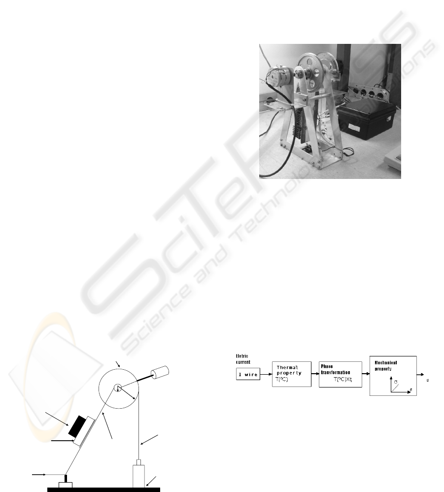
Figure 2 shows a picture of the actuator. The signal
conditioning module is composed by a constant
current amplifier that supplies up to 1A the electric
current to heat the SMA wire and by a voltage
amplifier/filter connected to the potentiometer.
Load
Common wire
Potentiometer
Pulley
SMA
wire
+5V
Current input
C
1
Thermoelectric
tablet
r
2
r
1
Figure 1: Diagram of the SMA actuator.
The module is connected to a computer (Pentium
100MHz) by mean of a 10bits AD/DA board. The
thermoelectric tablet is constantly powered by a 5V
tension.
A Matlab/Simulink software was used to acquire and
process the data from the potentiometer, and to send
the command to the current that must be imposed to
the SMA wire. Such software is flexible, and several
control algorithms can be easily implemented.
Furthermore, all graphical and mathematical tools
provided by Matlab/Simulink can be used. The
interface with AD/DA board was developed by
means of a low-level code included in the software.
Figure 2: Picture of the actuator.
3 MATHEMATICAL MODEL
The model developed in the present work is based
on the formulations proposed by Ikuta, Tsukamoto
and Hirose (1991); Grant, Hayward and Lu (1997);
Ashrafiuon and Elahinia (2002), Hoder, Vasina and
Solc (2003) and Dutta and Ghorbel (2005). It is
composed by a thermal model, a phase
transformation model and a description of the
mechanical properties and dynamics of the system
(Figure 3).
Figure 3: SMA actuator model.
The main variables used in the model are:
i – electric current in the SMA wire (A)
T – SMA wire temperature (ºC)
ξ
- martensite fraction (0 a 100%)
σ
- mechanical stress in the SMA wire (N/m
2
)
ε
- deformation (strain) of the SMA wire (ΔL/L)
BIODEVICES 2008 - International Conference on Biomedical Electronics and Devices
56
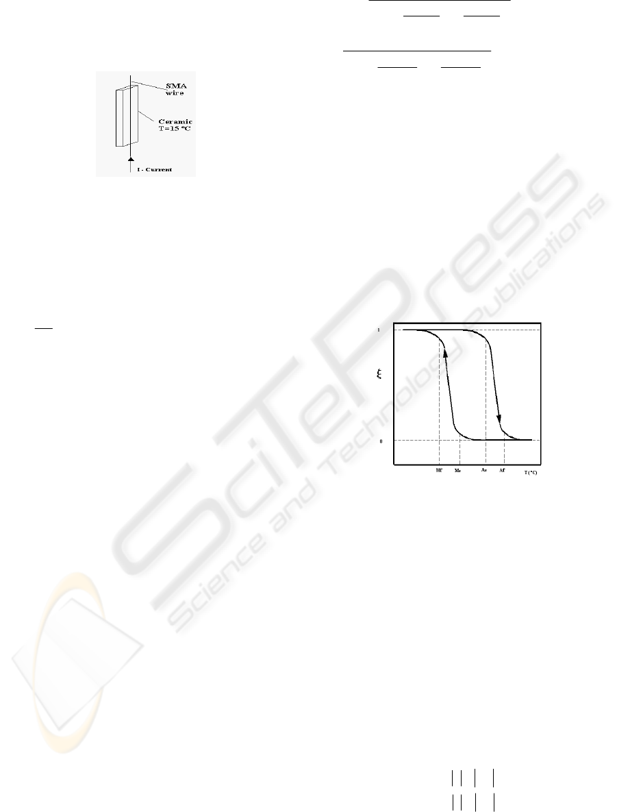
3.1 Thermal Model
Thermal model was base on the system shown in
Figure 4 in which the SMA wire touches the
thermoelectric element. The temperature of the
element is considered to be constant, equal to 15
0
C.
Figure 4: SMA wire and cooling element.
Considering several simplification hypothesis
(Grand, Hayward and Lu, 1997), the thermal model
can be written as (thermomechanical coupling is also
not included since the deformation rate of the SMA
wire is small, and such effect becomes important for
fast or highly oscillatory deformations):
).(.).(....
2
pambp
TTCTTAhRi
d
t
dT
cm −−−−=
(1)
In the previous equation, T
p
is the temperature on the
surface of the cooling element (15
o
C), T
amb
is the
ambient temperature (considered to be 20
o
C), h is
the natural convection coefficient per unity length of
SMA wire (in W/m
2
ºC/m) and C is the conduction
coefficient per unity length (in W/
ºC/m).
Furthermore, technical specifications of the SMA
wire Flexinol FLX 00870, 0.008’’, 70ºC) are given
by (Dynalloy, 2005):
m
- mass per unity length (2.10
-4
Kg/m)
p
c - specific heat (837 J/Kg.K)
R - electrical resistance per unity length ( 32Ω/m)
A
- external area per unity length ( 6.28.10
-4
m
2
/m)
d -diameter (2.10
-4
m)
The parameters h and C are very difficult to estimate,
since they depend on several variables. A rough
estimation of such parameters, based on the theory
exposed in Incropera and Witt (1998), are C = 0.4
W/
o
C/m and h=6.55 W/m
2
ºC/m. In the sequel, an
identification procedure will be used to obtain values
closer to the real ones.
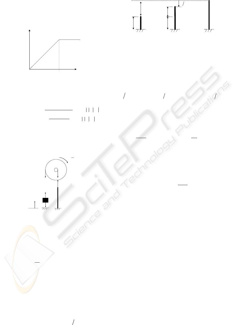
3.2 Phase Transformation
During heating, occurs the transformation between
Martensite (M) to Austenite (A), and during the
cooling phase, the opposite transformation occurs.
Basic equations that model such transformations, as
a function of temperature, are given below (Ikuta,
Tsukamoto and Hirose, 1991):
⎥
⎦
⎤
⎢
⎣
⎡
⎟
⎠
⎞
⎜
⎝
⎛
+
−
−
+
=
2
2.6
exp1
AfAs
T
AsAf
m
ξ
ξ
(heating)
A
A
MfMs
T
MsMf
ξ
ξ
ξ
+
⎥
⎦
⎤
⎢
⎣
⎡
⎟
⎠
⎞
⎜
⎝
⎛
+
−
−
+
−
=
2
2.6
exp1
1
(cooling) (2)
where As and Af are the initial and final temperature
of austenite transformation respectively; Ms and Mf
are the initial and final temperature of martensite
transformation respectively,
ξ
m
is the highest
martensite fraction during cooling and
ξ
A
is the
initial value of martensite fraction during cooling.
Typical values are As=68ºC, Af= 78ºC, Ms=52ºC and
Mf= 42ºC (Dynalloy, 2005). However, such values
may present variations up to ±15
o
C, and an
identification procedure will be applied to evaluate
the correct values for the wire used in the
experimental actuator. Phase transformation is
shown in Figure 5, and the hysteresis gets evident
(Holder; Solc and Vasina, 2003).
Cooling
Heating
Histeresis
Figure 5: Phase transformation plot.
3.3 Mechanical Properties and
Dynamics
Mechanical properties of shape memory alloys are
obtained by means of a multiple layer model. The
austenite phase is characterized by an elastic
behavior. The martensite phase presents a behavior
that seems to be plastic, deformed by a small stress
(Ikuta, Tsukamoto and Hirose, 1991). So, for
ξ
= 0
(full austenite), the stress-strain relation is given by:
ε
σ
.
AA
E
=
(3)
where
A
σ
is the mechanical stress in the austenite
portion of the alloy and E
A
is the austenite Young’s
Modulus. In the other way, when ξ = 1 (full
martensite), the stress-stain relation is given by:
mymymm
mymm
E
E
εεεσ
εεεσ
>=
≤=
if .
if .
(4)
NEW DEVELOPMENT ON SHAPE MEMORY ALLOYS ACTUATORS
57
E
m
is the martensite Young’s Modulus ,
ε
my
is the
martensite maximum elastic deformation,
σ
m
is the
maximum stress in the martensite. The martensite
mechanical behavior is illustrated in the fig. below:
σ
ε
ε
my
Figure 6: Martensite mechanical behaviour.
Considering then the case with 0<ξ< 1, the stress-
strain relation is given by:
⎪
⎪
⎩
⎪
⎪
⎨
⎧
>
−
−
=
≤
−+
=
⇒−+=
my
A
my
my
AM
AM
E
Em
EE
εε
ξ
εξσ
ε
εε
ξξ
σ
ε
σξσξσ
for
).1(
..
for
.).1(.
).1(.
(5)
The dynamics of the actuator is now considered. A
simplified diagram of the actuator and the main
forces are shown in the Figure 7, where the
coordinate x represents the position of the load.
T
1
T
1
T
2
T
2
r
2
x
=
ω
x
m
L
.g
Figure 7: Diagram of the actuator and main forces.
The traction T
1
holds the load, T
2
is the traction
acting on the SMA wire and
ω
is the angular
velocity of the pulley. So, being J the moment of
inertia of the pulley and m
L
the mass of the load,
using the basic laws of Mechanics one obtains:
2
1221
..
r
x
JrTrT
=+−
; xmTgm
LL
.
1
=+− (6)
Traction T
2
may be estimated using a linear spring
analogy. Figure 8 shows the wire in three possible
states. In the austenite phase, the “spring” presents
its initial length l
0
. In the martensite phase, the wire
reaches its maximum length l
wire
, that correspond to
the situation in which the load position is x=0. The
difference between l
0
and l
wire
is approximately 4%
of the l
wire
. In an intermediate phase, the “spring”
elongation
lΔ is given by nxl
fio
−%.4 .
Austenite
0
l
Martensite
(x=0)
Intermediate
nx
0
l
wire
l
wire
l%.4
≅
l
Δ
Figure 8: Spring analogy.
So, the traction is given by
(
)
nxlKlKT
wire
/.04,0..
2
−
=
Δ
=
, where K is the
equivalent stiffness coefficient of the wire. Including
a damping term, the equation of motion of the
actuator becomes:
(
)
nKlgmxnKxcxmrJ
wireL
L
)04.0(...
2
2
2
+−=+++
(7)
The stiffness coefficient K may be evaluated using
(5). Assuming elastic behavior, being A
wire
the
sectional area of the wire, one obtains:
[
]
ε
ξ
ξ
σ
.).1(.
AM
EE
−
+
=
or
[]
0
2
.).1(.
l
l
EE
A
T
AM
wire
Δ
−+=
ξξ
(8)
Finally, considering that martensite stress will be
higher than its elastic limit, it may be assumed that it
will present a full plastic behavior, with a very small
stiffness. So, E
M
may be excluded from (8), resulting
the approximation:
[]
0
.).1(
l
A
EK
wire
A
ξ
−= (9)
4 PARAMETER
IDENTIFICATION
Thermal parameters C and h, as well as the
transformation temperatures (Ms, Mf, As and Af)
must be accurately evaluated using a proper
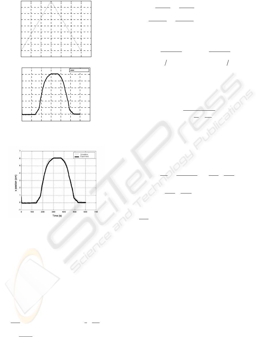
experimental procedure. A ramp excitation was
induced in the wire, inducing a displacement of the
load, as shown in Figure 9.
Using an optimization algorithm based on
Quadratic Sequential Programming (SQP), the
model parameters were adjusted in order to make the
model to recover the measured position accurately.
The following parameters were obtained,: C=0.255
W/
o
C/m, h=7 W/m
2
ºC/m, Ms = 66
o
C , Mf = 34ºC
As = 53ºC, Af = 93ºC. The comparison between the
measured position ant that obtained by the model
simulation is given in Figure 10. A good accuracy of
the model is verified.
BIODEVICES 2008 - International Conference on Biomedical Electronics and Devices
58
0 100 200 300 400 500 600 700
-0. 1
0
0.1
0.2
0.3
0.4
0.5
0.6
0.7
0.8
Tem po (s )
Corrente (A)
Time (s)
Current (A)
(a)
0 100 200 300 400 500 600 700
-1
0
1
2
3
4
5
6
7
Tempo(s)
Deslocamento(cm)
Experimento
Time (s)
x position (cm)
Experiment
(b)
Figure 9: (a) Current ramp excitation; (b) Position of the
load.
Figure 10 Comparison between simulation and
experimental results
5 CONTROL SYSTEM DESIGN
In order to apply the sliding mode control to the
SMA actuator, the model previously developed must
be adapted, following the formulation exposed in
Slotine and Li (1991). After some algebraic
manipulation using (1) and (2), the dynamics of
phase transformation can be written as:
ubf ).()(
ξξξ
+=
(10)
with:
()
⎟
⎟
⎠
⎞
⎜
⎜
⎝
⎛
⎟
⎟
⎠
⎞
⎜
⎜
⎝
⎛
+
⎟
⎟
⎠
⎞
⎜
⎜
⎝
⎛
−
−
+−+−−−
−
= b
ka
chAcThATkk
mc
a
f
Pamb
P
1ln
1
)()()()(
0
2
0
0
ξ
ξ
ξξξ
ξ
ξ
()
Rkk
mc
a
b
P
2
0
0
)()()( −−−
−
=
ξξξ
ξ
ξ
;
2
Iu =
and
⎪
⎪
⎩
⎪
⎪
⎨
⎧
<=−=
+
=
−
=
>==
+
=
−
=
0 if ;1;
2
;
2.6
0 if 0;;
2
;
2.6
0
0
Tk
MM
b
MM
a
Tk
AA
b
AA
a
AA
fs
fs
M
fs
sf
ξξξ
ξξ
Using (1) and (9), the dynamics of the motion can
also be written as:
Δ
−
+−=
−
++
n
K
gmx
n
K
xcxI
L
)1()1(
0
2
0
ξξ
(11)
With
(
)
L
mrJI +=
2
2
;
00
lAEK
wireA
=
and
wire
l04.0=Δ
. In equations (10) and (11), the variable
x is measured, but the variable
ξ
must be estimated.
This may be done considering a quasi-static
approximation to (11), making
0== xx
, that
results:
⎟
⎠
⎞
⎜
⎝
⎛
−
Δ
−=
2
0
1
ˆ
n
x
n
K
gm
L
ξ
(12)
Differentiating (11), and using (10), one obtains the
SMA model adequate to apply sliding mode control,
as proposed by Slotine and Li (1991):
ubfx ).()( xx +
=
(13)
with
(
)
T
xxx
ξ
=x
,
)(
)1(
)(
0
2
0
2
0
ξ
ξ
f
In
K
In
xK
x
In
K
x
I
c
f
⎟
⎠
⎞
⎜
⎝
⎛
Δ
−+
−
−
−
=
x
and
)()(
0
2
0
ξ
b
In
K
In
xK
b
⎟
⎠
⎞
⎜
⎝
⎛
Δ
−=x
.
So, the control action
2
iu = is given by:
(
)
)/(
~~
2)(
ˆ
)(
ˆ
1
2
φλλ
ssatKxxxf
b
u
SMd
−−−+−=
x
x
(14)
with
xxxs
~
~
2
~
2
λλ
++=
. )(
ˆ
xf and
)(
ˆ
xb
are the best
estimates of the functions in model (13), considering
the approximate values for the parameters and the
estimate of the variable
ξ
given in (12).
d
x is the
desired position of the actuator load (set-point),
λ
is
a positive constant related to the cut-off frequency of
the closed-loop system,
φ
is the boundary layer
thickness to avoid control chattering and K
SM
is a
control gain related to the modeling and parameter
estimation errors. A detailed description of the
control design may be found in Slotine and Li
(1991).
6 EXPERIMENTAL RESULTS
The control logic previously developed was applied
to the experimental prototype, and the performance
NEW DEVELOPMENT ON SHAPE MEMORY ALLOYS ACTUATORS
59
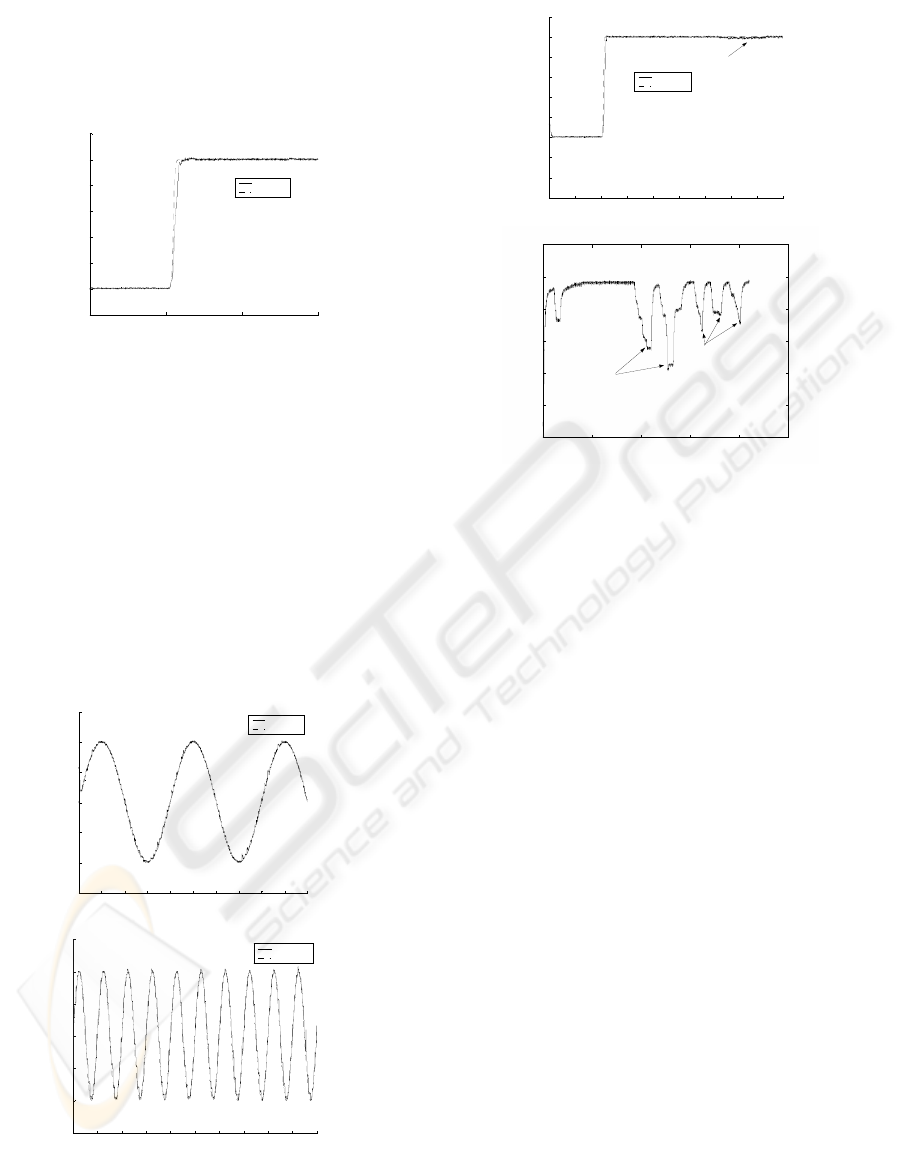
of the closed loop system could be evaluated. Figure
11 shows a reference step of 2.5cm applied at t=10s.
Control parameters are λ=40; φ=1,6 and K
SM
=64.
The 5% settling time obtained is 0,23s, and the
maximum overshoot is 0,6%.
5 10 15 20
1.5
2
2.5
3
3.5
4
4.5
5
Tim e(s )
X P os it i o n ( c m )
Position
Reference
Figure 11: Step response of the SMA actuator.
A harmonic set-point was applied to the actuator,
with amplitude of 1cm and periods of 20s and 5s
(Figure 12. It can be seen that, despite a small
oscillation around the set-point, the system follows
the reference with good accuracy. Tests with
decreasing periods indicated a 0.69Hz cut-off
frequency, despite of a 0.37Hz obtained with a
conventional PID controller. Finally, a cooling
disturbance was applied, created by a computer
cooler fan directed toward the SMA wire (Figure
13). The robustness of the controller can be verified,
by comparing the response with the open-loop
response.
0 5 10 15 20 25 30 35 40 45 50
0.5
1
1.5
2
2.5
3
3.5
Tim e(s )
X Position(cm)
Position
Reference
(a)
0 5 10 15 20 25 30 35 40 45 50
0.5
1
1.5
2
2.5
3
3.5
Tim e(s )
X Position(cm)
Position
Reference
(b)
Figure 12: Harmonic set-point response of the SMA
actuator (cm amplitude). (a) 20s; (b) 5s period
0 5 10 15 20 25 30 35 40 45
0.5
1
1.5
2
2.5
3
3.5
4
4.5
5
Tim e(s)
X Position(cm)
Position
Reference
cooling
(a)
0 50 100 150 200 250
2
2.5
3
3.5
4
4.5
5
Tim e (s )
X Position (cm)
cooling
cooling
(b)
Figure 13: Cooling disturbance response of the SMA
actuator (a) closed-loop; (b) opened-loop
7 CONCLUSIONS
A novel SMA actuator was proposed, using the
thermoelectric effect for cooling the SMA wire. An
experimental prototype was built, and a
mathematical model was developed. The model
parameters were adjusted by means of an
experimental identification procedure. The validated
model was then used to design a sliding mode
controller. Such controller is able to deal with model
and parameter uncertainties, and also with non-linear
effects. Closed-loop preliminary results obtained in
the experimental set-up showed that the proposed
actuator presents a good dynamic response and low
sensibility to disturbs of load and ambient cooling.
So it is recommended in application with SMA
devices.
ACKNOWLEDGEMENTS
The authors would like to express their gratitude for
the IPT (Institute for Technological Research - São
Paulo, Brazil) for supporting this research and for
CNPq (National Council for Scientific and
Technological Development), Research Process
Number 484232/2006-1.
BIODEVICES 2008 - International Conference on Biomedical Electronics and Devices
60

REFERENCES
Asada, H.H. and Mascaro S., 2002, “Wet Shape Memory
Alloy Actuators”, MIT Home Automation and
Healthcare Consortium, Phase 3 Final Report, Boston,
USA.
Ashrafiuon, H. and Elahinia H.M., 2002, “Nonlinear
Control of a Shape Memory Alloy Actuated
Manipulator”, ASME Journal of Vibration and
Acoustics, Vol. 124, pp.566-575.
Dutta, S.M. and Ghorbel, F.H., 2005, "Differential
Hysteresis Modeling of a Shape Memory Alloy Wire
Actuator," IEEE/ASME Transactions on
Mechatronics, Vol. 10, Issue 2, April , pp. 189-197.
Dynalloy, Inc., 2005, “Flexinol – Wire specifications”.
Available at: http:// www.dynalloy.com. Acess: 20
Dec. 2005.
Furuya, Y. and Shimada H., 1990, “Shape Memory
Actuator for Robotic Applications, Engineering
Aspect of Shape Memory Alloys”, Butterworth-
Heinemann, London, pp 338-355.
Gorbet, B.R. and Russel A.R., 1995, “Improve the
Response of SMA Actuators”, IEEE International
Conference on Robotic and Automation, Vol. 3, May,
pp. 2299-2303.
Grant, D., Hayward V. and Lu A., 1997, “Design and
Comparison of High Strain Shape Memory Alloy
Actuators”, International Conference on Robotic and
Automation, Albuquerque, New Mexico, 260-265.
Hoder K., Vasina, M. and Solc F., 2003, “Shape Memory
Alloy- Unconventional Actuators”, International
Conference on Industrial Technology ICIT, Maribor,
Slovenia, pp. 190-193.
Ikuta K., Tsukamoto M. And Hirose, S., 1991,
“Mathematical Model and Experimental Verification
of Shape Memory Alloy for Designing Micro
Actuator”, Proc. of the IEEE on Micro
Electromechanical Systems, an Investigation of
Microstructures, Sensors, Actuators, Machines, and
Robots, pp.103-108.
Incropera, P.F. and Witt, D.P.D., 1998, “Fundamentos de
transferência de calor e de massa”, 4 ed., Rio de
Janeiro, LTC (In Portuguese).
Slotine, J.J.E. and Li, W., 1991, “Applied nonlinear
control”, Englewood Cliffs: Prentice –Hall, USA.
Tanaka,Y. and Yamada Y., 1991, “A Rotary Actuator
Using Shape Memory Alloy for a Robot, and Analysis
of the Response with Load”, IEEE/RSJ International
Workshop on Intelligent Robots and Systems IROS
’91, Osaka, Japan, pp1163-1168.
NEW DEVELOPMENT ON SHAPE MEMORY ALLOYS ACTUATORS
61
