
THE DESIGN OF BIAXIAL JOINT FOR MOBILE
ELECTRONICS WITH THE ANALYSIS ON ARTHROSIS
Zhao Danpu, Yi Qiang, Nie Chenghui, Chen Ken, Liu Li
Dept. of Precision Instruments and Mechanology, Tsinghua University, Beijing 100084, China
Xu Leon, Salo Antti
Nokia Research Center, Beijing 100013, China
Keywords: Bionic, joint, arthrosis.
Abstract: To bring forward the new form factors is one of the key drivers for future mobile electronic devices. On the
other hand, some form factors in nature with evolution process have been the excellent and adaptive. In this
paper, we pay attention to the characteristics of arthrosis, researched on the difference between the arthrosis
and machine joint. Then the essentials and parameters of the biaxial joint design were introduced. After that
a biaxial joint concept for portable electronics based on the bionic principle was proposed. Finally, we
provided the statics analysis of the biaxial joint.
1 INTRODUCTION
In recent years, more and more mobile electronic
devices have become an improtant part of people’s
life. One of the key drivers for future electronic
mobile devices is to enable drastic change of the
physical appearance of mobile terminals with totally
new product category possibilities.
The clamshell type electronic mobile device is
the most popular type. The joint divided into two
parts and the opening angle is general at 160 degree.
Obviously, the structure of the joint limits the
opening angle. Another problem of this type of
communication between two parts is secular fold. So
many researches pay attention to the design of rotary
joint.
Most of rotary joints only have one axial and two
parts of joint turned encircling the axial. Because of
the motion intervention, the friction cannot be
avoided.
In our research, the design of a biaxial joint
based on the bionic principle is introduced. The
biaxial joint has two perpendicular axes. Two pairs
of apposing movements take place along these axes
respectively and circumduction is permitted.
2 THE CHARACTERISTICS OF
ARTHROSIS
Locomotor system includes bones, joints and
muscles. Each bone is linked with joints. Every
arthrosis has some common structures. The typical
one is as Figure 1. Compare with the machine joint,
the arthrosis have some characteristics:
Figure 1: The structures of a typical synovial joint.
The articular surfaces are the smooth surfaces
composed by non-standard curve or surfaces.
The articular surfaces indirectly connect with
cartilages. The articular discs make joint surfaces fit
further with one another, increase stability of joints
and absorb large forces of compression and shear.
138
Danpu Z., Qiang Y., Chenghui N., Ken C., Li L., Leon X. and Antti S. (2008).
THE DESIGN OF BIAXIAL JOINT FOR MOBILE ELECTRONICS WITH THE ANALYSIS ON ARTHROSIS.
In Proceedings of the First International Conference on Biomedical Electronics and Devices, pages 138-142
DOI: 10.5220/0001048101380142
Copyright
c
SciTePress
The ligaments are the driver of body structures.
Usually, one arthrosis connects with one more
ligaments. When the arthrosis move, the ligaments
around it will cooperated drive the arthrosis to move
with a non-repeated track.
3 DESIGN OF THE BIAXIAL
JOINT
3.1 The Essentials of the Joint Design
In this project, a bionic joint would be designed for
the joint of electronic devices. Therefore some
essentials of the main joint design as follow:
While design joints the rolling friction should be
selected for decreasing the affect of friction.
Usually the wire is easily failed when folded
repeatedly. So the wire should cling on the joint
surface to acquire the support. Also the curvature
radius of joint should be enlarged at full steam.
As articular discs, some filling would be
accepted and it can make joint surfaces fit further
with each other, increase stability of joints and
absorb the large forces of compression and shear.
Imitate the body drivers, some special drivers
should be selected with the small structure and for
parallel movement.
3.2 The Surfaces Design of Joint
In body, the hinge joint has two parts, concave and
convex, and movement takes place on sagittal plane,
e.g., the elbow and ankle. With the analysis on the
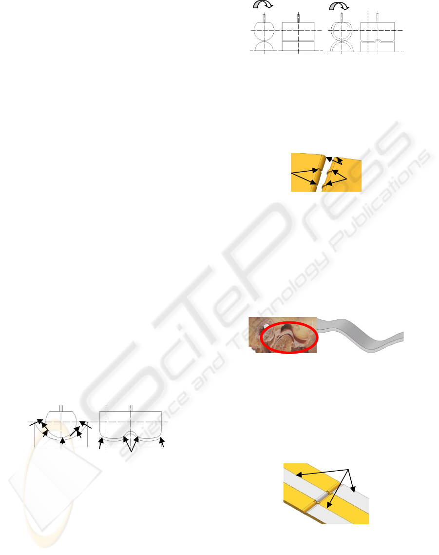
structures of hinge joint, it is described as Figure 2.
Figure 2: The sketch of hinge joint. The N means the
support forces, f is the frictions, F is the transverse forces.
For avoiding the friction, the concave part will be
replaced by convex, and the two parts are tangent.
See Figure 3 (a). Transverse displacement should
also be considered. Simulate the cooperation of the
neck and convexity, some keys and slots should be
designed. So the joint is showed as Figure 3 (b).
(a) (b)
Figure 3: The sketch of joint.(a) joint with double convex,
(b) joint with key and slot.
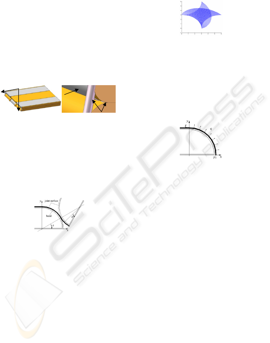
As the analysis before, the curvature radius should
be enlarged. So the section of the joint part can be
designed as demisemi circularity. So the biaxial joint
structure is described as Figure 4.
Figure 4: The sketch of final biaxial joint structure.
3.3 The Design of Medium in Joint
For the fit and stable of the structure of synovial
joints, there are other structures inside the joint, such
as articular cartilages.
See the sagittal section of temporomandibular
joint in Figure 5 (a), the articular disc suit on the
surfaces of two joint parts.
(a) (b)
Figure 5: (a) The sagittal section of temporomandibular
joint. (b) The sketch of connective band.
Simulate the structure and function of the articular
disc, a connective band is design as Figure 5 (b). It is
suited on the surfaces of two joint parts.
For keeping balance, three bands from different
directions interlude the joint cavity. See Figure 6.
Figure 6: The biaxial joint with connective band.
3.4 The Design of the Joint Driver
In the movement of articular, muscles drive the
joint. They compress and elongate to change the
direction between two attachments on the different
N
f
N
N
f
F
F F F
Connective band
Slot
Key
Dot for muscle
THE DESIGN OF BIAXIAL JOINT FOR MOBILE ELECTRONICS WITH THE ANALYSIS ON ARTHROSIS
139
bones. The greatest excellence of using muscle
drivers in joint is the minimal volume. In this
research, artificial muscles would be selected as
joint drivers.
In the biaxial joint, one part would turn around
the other back and forth. Therefore two couples of
drivers should be emplaced on the double side of the
joint.
For balance, they should be distributed
symmetrically. In this design, the turn range of the
joint can be from 0 to 360 degree. See Figure 7.
Figure 7: The biaxial joint with artificial muscles.
4 STATICS ANALYSIS OF THE
BIO-JOINT
In this paper, because of the tangent motion between
two joint surfaces, the slip resistance can be ignored.
Predigesting the joint structure, the joint surfaces
with connective band can be modelled as Figure 8.
Figure 8: The model of the system.
4.1 The Motion Track
If we establish the coordinate at one of the circles,
the other one rotated on its surfaces. So the motion
track equation of discretionary point on the moving
circle can be founded as
X=2Rcosθ-Rsin(π/2-2θ+φ) (1)
Y2Rsinθ-Rcos(π/2-2θ+φ)
(2)
Here φ is the angle between the point on the joint
surface and underside of the joint.
Figure 9: The motion track of the joint.
When the φ changed from 0 to π/2, we draw one
track with every 0.25π degree. And the tracks are
described as Figure 9 in area XY.
4.2 The Forces of the System
For ensuring the reliability of connection of two
joint surfaces, beforehand force F would be added
on the bands. The forces are showed in Figure 10.
Figure 10: The sketch of the forces on system.
Here, F is the beforehand force, q is the forces
density. So the force on arc with the length as Rdθ is
f=qRdθ.
The component of forces on the axial X and Y is
f
x
=qRdθ
·
sinθ, f
y
=qRdθ
·
cosθ
(3)
According to the principle of forces balance, it
can be described as
θθ
π
dqRF
∫
=
2/
0
sin
(4)
Then
q=F/R (5)
4.3 The Stress
4.3.1 Stress on the Band
As it described before, in this design the fix up of
joint is realized by some connective bands. So the
bands are the primary force suffering object. With
the repeatedly folding, it should be laid-back and
wearing. Thereby the integrality and reliability of
structure would be destroyed. So in this part, the
stress of connective band would be analyzed.
Firstly, the normal stress for the beforehand
forces can be
σ
bF
=F/A
b
(6)
Artificial muscle
Connective band
Artificial muscles
BIODEVICES 2008 - International Conference on Biomedical Electronics and Devices
140
Here, A
b
is the section area of connective band.
Then, the normal stress for bending moment is
σ
bM
=My/I
bz
(7)
Here, y is the direction between the point and central
on section. And M=F(R-Rcosθ) is the bending
moment on the section,
∫
=
b
A
bbz
dAyI
2
is the
moment of inertia for axial
z.
So the whole normal stress on connective band
can be described as
σ
b
=σ
bF
+σ
bM
= F/A
b
+ My/I
bz
(8)
The maximal normal stress on connective band is
at the point when
y=y
max
. It changed with θ can be
described as Figure 11 (a).
(a) (b) (c)
Figure 11: The maximal stress on connective band. (a)
Normal stress changed with θ, (b) Shear stress changed
with θ, (c) The τ
b
change with y.
At the same time, the shear stress at y on section
can be showed as
τ
b
=3F
bs
(1-4y
2
/h
b
2
)/2bh
b
(9)
Here,
h
b
is the thickness of band, b is the breadth
of it, and F
bs
=Fsinθ is the shearing force on the
section.
In Figure 11 (b) the curve of maximal shear
stress changed with
θ is described.
A maximum of F
bs
when θ=π/2 can be get. So
the
τ
b
with such F
bs
can be described as Figure 11 (c).
The maximum of
τ
b
can be found when y=0.
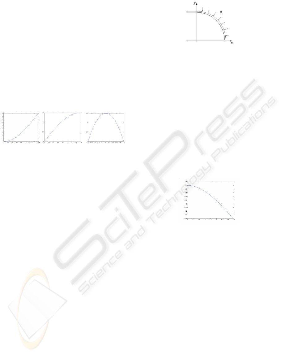
4.3.2 Stress on the Joint Surface
Because of the no direct touch between two joint
surfaces, the joint surface gets the press form
connective bands only when it turned. See Figure
12. Due to the radial press with the forces density
q,
the axial loads is
F, so the normal stress from the
press on the joint surface is
σ
jF
=qR/ A
j
=F/A
j
(10)
Here, A
j
is the section area of joint surface.
Figure 12: The sketch of the forces on joint surface.
Then, the normal stress for bending moment on
the joint surface is
σ
jM
=My/I
jz
(11)
Here,
y is the direction between the point and central
on section. And
()
∫
−=
θ
ϕϕθ
0
2
dqRM sin
is the
bending moment on the section,
∫
=
j
A
jzj
dAyI
2
is
the moment of inertia for axial
z.
So the whole normal stress on joint surface is
σ
j
=-σ
jF
+σ
jM
= -F/A
j
+ My/I
jz
(12)
The maximal normal stress on joint surface is at
the point when
y=y
max
. It changed with θ can be
described as Figure 13.
Figure 13: The maximal normal stress changed with θ.
Also, the shear stress is existed on the joint
surface. The shear stress at
y on section can be
showed as
τ
j
=3F
js
(1-4y
2
/h
j
2
)/2bh
j
(13)
Here,
h
j
is the thickness of joint, and
()
∫
=
θ
ϕϕθ
0
js
d-qRF cos is the shearing force.
So we can get a similar curve as Figure 12, the
maximal shear stress changed with
y is described.
4.4 The results
In this design, when one surface round on another,
although the point on one changed his track
direction after it pass the tangency part, but due to
the tangent point track is arc, the move is smooth.
Based on the forces analysis, there’s no slip
resistance between two surfaces. It’s the virtue of
such design, because it defence the energy wasting
and surfaces wearing; and at the same time, it is a
THE DESIGN OF BIAXIAL JOINT FOR MOBILE ELECTRONICS WITH THE ANALYSIS ON ARTHROSIS
141

shortcoming, because it can not stop at any part with
friction. But here we bring out the driver of artificial
muscle, the orientation is ensured.
When selecting the material of connective band,
only if the allowed stress is larger than maximal one
gained before, reliable structure can be accepted.
5 CONCLUSIONS
As one of the most important part of electronic
mobile devices, the design of joint catches the great
attention of researchs. One of the key drivers for the
devices is to enable drastic change of the physical
appearance of mobile terminals with totally new
product category possibilities. In this paper, some
characteristics of the arthrosis are analyzed. And we
bring out a biaxial joint for electronic mobile
devices based on the bionic principle. At last, the
statics of such biaxial joint is analyzed.
REFERENCES
Stephanie, R., Michelle, M., Stephen, E., 2004. Anatomy
for Diagnostic Imaging, SAUNDERS. Spain, 2
nd
edition.
Liu, Z. Y., 2007. Chinese-English Textbook of Systemic
Anatomy, Science Publishing Company, China, 1
nd
edition.
William, C. M., 2005. Smart Technology for Aging,
Disability, and Independence: the state of the science,
WILEY-INTERSCIENCE. New Jersey, 1
nd
edition.
Ben P., 1975. Dynamic Anatomy and Physiology,
Macmillan publishing Co. American, 1
nd
edition.
Zhou X., Zhao Zh., 2000. Establishment of TMJ model
including mandible by mean s of three-dimensional
finite element method. J Pract Stomatol, Vol. 16 (1),
P17-19.
LI X., ZHANG R., 2004. Artificial Muscles Based on
Conducting Polymers. Journal of Materials Science &
Engineering, Vol. 22 (1), P128-131.
CAO X., WANG B., 2004. The Decision of Fatigue Stress
Table of Belt. Journal Of Wuhan University Of
Technology, Vol. 26 (9), P67-70.
BIODEVICES 2008 - International Conference on Biomedical Electronics and Devices
142
