
OMNIDIRECTIONAL VISION TACKING SYSTEM BASED ON
KALMAN FILTERING AND OMNICAMSHIFT
B. Allart, B. Marhic, L. Delahoche
LTI – IUT Informatique Avenue des facultés – Le Bailly - 80025 Amiens Cedex 1, France
O. Rémy-Néris
CHU of Brest, 5 avenue Foch 29200 Brest, France
A. M. Jolly-Desodt
GEMTEX - 9, rue de l'Ermitage - 59056 Roubaix Cedex 1, France
Keywords: Rehabilitation Robotics, Autonomous platform, wheelchair tracking, CAMSHIFT, Kalman filter.
Abstract: This paper deals with a robotised assistance dedicated for Handicap person. In this paper, we will propose to
discus about one of the main functionality of this project: the tracking of the wheelchair from an
autonomous mobile platform on which the Manus (c) arm is mounted. To ensure the tracking, we will
present a method based on Kalman filter’s algorithm that we have upgraded in combination with two
Kalman filtering levels. The first level permits an estimation of the wheelchair configuration in its
environment and the second is used to compute the mobile platform configuration in connection with its
environment. The association of the two filtering processes allows a robust tracking between a mobile target
(wheelchair) and a mobile observer (assistive platform). More over, the team project was also composed
with a clinical group; hence we present some interesting real-life testing of this technical assistance.
1 INTRODUCTION
Our laboratory works on an assistive prehensile
mobile robot project and has to ensure the tracking
of a wheelchair from the mobile platform. In this
article, we propose an approach to solve the problem
known as target motion analysis (TMA). We
propose a target tracking filter based on a
probabilistic approach with the Kalman Filtering
which will be fed by omnidirectional vision sensors
and dead-reckoning sensors mounted on the mobile
platform. The problem of tracking is classical in the
world of robotics. It’s generally linked to the data
association stage and state estimation. The data
association problem is that of associating the many
measurements made by a sensor with the underlying
states or trajectories that are being observed. It
includes issues of validating data, associating the
correct measurement to the correct states or
trajectories, and initializing, confirming or deleting
trajectories or states. The Probabilistic Data
Association Filter (PDAF) for single target and the
Joint Probability Data Association Filter (JPDAF)
(Y. Bar Shalom et al, 1988), (Bar-Shalom Y et al,
1995) for multiple targets are two inescapable
approaches. They are both Bayesian algorithms that
compute the probability of correct association
between an observation and a trajectory. The general
JPDAF framework can be implemented using Monte
Carlo techniques, making it applicable to general
non-linear and non-Gaussian models (D.Schulz et al,
2003).
A second classical paradigm of data association
is the Multiple hypothesis tracking (MHT)
(S.Blackman, 1986) which permits to represent
multimodal distributions with Kalman filters (Y. Bar
Shalom et al, 1988). It has been used with great
effectiveness in radar tracking systems, for example.
This method maintains a bank of Kalman filters,
where each filter corresponds to a specific
hypothesis about the target set. In the usual
approach, each hypothesis corresponds to a
9
Allart B., Marhic B., Delahoche L., Rémy-Néris O. and M. Jolly-Desodt A. (2008).
OMNIDIRECTIONAL VISION TACKING SYSTEM BASED ON KALMAN FILTERING AND OMNICAMSHIFT.
In Proceedings of the First International Conference on Biomedical Electronics and Devices, pages 9-16
DOI: 10.5220/0001049100090016
Copyright
c
SciTePress
postulated association between the target and a
measured feature.
For our application, we have chosen to use two
Kalman filters to solve the problem of target
tracking from a mobile observer.
The originality of this approach in connection
with the classical solutions resides in two points:
• Solving the problem of data association with a
dedicated image-processing filter (camshift).
• Solving the problem of simultaneous moving of
the target and the tracker with two embedded
Kalman filters.
The combination of the prior two points
contributes to solving the non-linearity problem of
the global filter.
Paper Organisation. In the next paragraphs (§1.1,
§1.2, §1.3, §1.4), we will mention the specific
context of this study, outline the perception system
and describe the functionalities of the proposed
assistive platform. After that in part 2, we will
briefly explain the first tracking method (1TM)
based on the iterative algorithm CAMSHIFT with a
specific use for omnidirectional images. We also
present very original clinical results of the tests
made under genuine conditions by disabled people.
In the last part (§3), we deal with the multi-level
Kalman filtering tracking (second Tracking Method,
2TM). Moreover, in this section, we will describe
our Embedded Extended Kalman Filtering (EEKF).
Finally (§4), we will conclude with an explanation
of the experimental results.
1.1 Context Overview
This project, ARAP (Robotised Assistance for
Prehensile Help), came into being from a human
synergy, which grew out of a definition of problems
faced by peoples of reduced mobility. The idea of
robotised assistance for handicapped people
followed an observation: there is generally a
significant delay between technology, no matter how
advanced, and assistance for peoples of reduced
mobility. Above all, however, this project meets a
social demand, that was defined by patients of
reduced mobility confined to the Berck Hopale
group (Hospital), who are taking part in this project.
An interesting specificity of this project was
composing a strongly plural-disciplinary team:
• “Science for the Engineer” skills of the IUT of
Amiens (University of Picardie, Jules Verne) have
been used for the integration of a system of
detection on the mobile platform and for the
development of the prototype.
• The “Human and Social Science” team was in
charge of the psychological impact of this mobile
assisting platform on the end-user.
• The “Clinical group” (the Calvé Centre in
Berck-Sur-Mer) used its clinical knowledge of the
problem of disability, which will allow an
evaluation of the work done.
A lot of work has been carried out in connection
with the problems defined by technical assistance.
Some of them are describe in (B.Marhic et al, 2006).
We have proposed studying the technical,
psychological and clinical impact of robotised
assistance for persons of reduced mobility by
combining a mobile platform with a grasping arm in
its usual role as robotics for handicapped persons
(robot arm MANUS®).
1.2 Main Perception System
The mobile platform, in other words “the observer”,
is mounted by the two classical kinds of sensors; i.e.
the Inner Navigation System (INS) and the External
Position System (EPS). The INS are dead-reckoning
sensors and the EPS is a stereoscopic
omnidirectional vision sensor used in a goniometric
mode (figure 2). Moreover, this exteroceptive
sensorial system is also used for the target
observation (wheelchair) as a “classical” vision
system involving the intrinsic properties (colour).
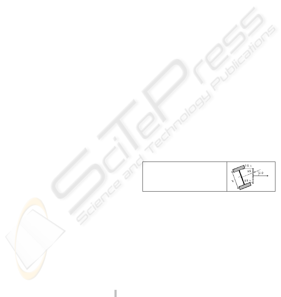
The well-known equation (first order) of “dead-
reckoning”, considering the figure 1 is given by:
X
m
= [x
m
, y
m
, θ
m
]
T
(
)
()
⎪
⎪
⎩
⎪
⎪
⎨
⎧
+=+
⋅+=+
⋅+=+
)()()1(
)(sin)()()1(
)(cos)()()1(
nnn
nnSnn
nnSnn
mm
m
mm
m
mm
yy
xx
δθθθ
θδ
θδ
Figure 1: Small movements of the robot during a period.
Stereoscopic Omnidirectional Vision System.
Main vision applications in mobile robotics use the
classical pinhole camera model. Depending on the
lens used, the field of view is limited. Nevertheless,
it is possible to enlarge the field of view by using
cameras mounted in several directions (H. Ishiguro,
S. Tsuji, 1993) but the information flow is very
important and time consuming.
We have opted for a catadioptric vision system
(figure 2).
BIODEVICES 2008 - International Conference on Biomedical Electronics and Devices
10
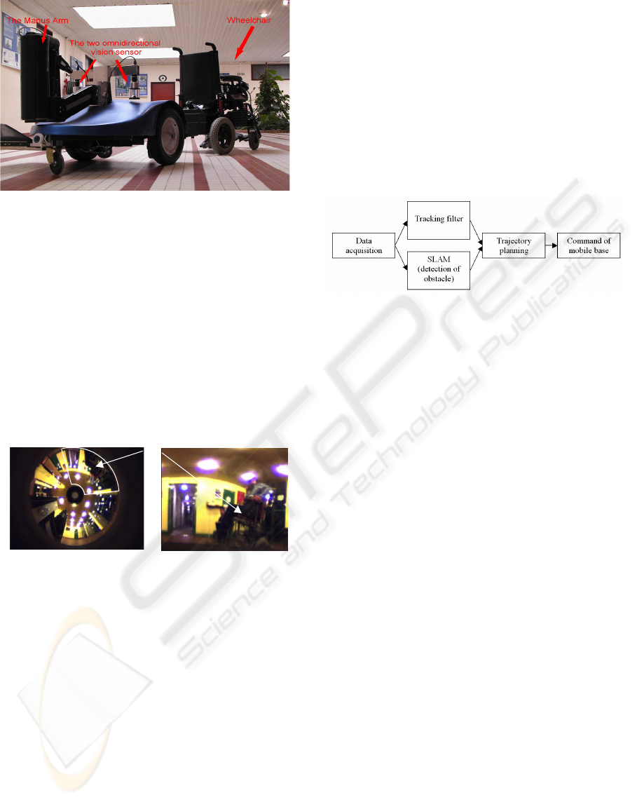
Figure 2: The mobile platform and stereoscopic sensors.
There are many advantages to using an
omnidirectional vision sensor. Firstly, in one
acquisition, we obtain a full view of the environment
without using a sophisticated mechanical system.
Secondly, the same system can be used as EPS and
also as a “bearing sensor”. Finally, even if the visual
interpretation of omnidirectional pictures is difficult,
it is possible to compute a “classical perspective
view” of the scene. The previous functionality is not
discussed in this paper.
The figure 3 shows an omnidirectional view of
an environment with a wheelchair.
A wheelchair
Figure 3: (left) an omnidirectional view of a scene with a
wheelchair in the field of view. (right) “un-warped”
picture of the white area from the omnidirectional view.
1.3 Main Functional Specificities
Two functional specificities have been integrated
into the robotised assistance (ARAP). Firstly
(automatic mode), the mobile platform follows the
patient’s wheelchair whenever the patient does not
wish to use it. Secondly, a remote controlled mode
for the grasping arm MANUS
(R)
and for the mobile
base, used when the patient wishes to carry out a
task involving grasping.
1.4 Scientific Problematic
The two main scientific themes associated with the
automatic mode are the tracking and the path
planning according to the obstacle avoidance and
map building (locally). The coordination of the
tracking and of the detection of obstacles is very
important for the proper progress of our system.
The block diagram below (figure 4) shows the
concomitance between the local map and the
tracking phase. These can sometimes give
orientation orders to the mobile platform that are
contradictory.
In this paper, we focus only on the tracking
problem.
Figure 4: Coordination of tracking and detection of
obstacle.
2 1TM: OMNICAMSHIFT
We wished to achieve the greatest possible degree of
flexibility regarding the use of this robotic
assistance. We therefore did not want to restrict our
method to the use of one wheelchair in particular.
More over, the wheelchair is not equipped with any
particular marker; we have to track it as it is. Thus,
in the first stage, our strategy for wheelchair
recognition and tracking was based on a specific use
of the CAMSHIFT. We have named the calculation
of a CAMSHIFT directly into an omnidirectional
image “OmniCAMSHIFT”. (C. Cauchois et al, 2005)
The Continuously Adaptive Mean SHIFT
(CAMSHIFT) algorithm (Bradski, 1998), is based
on the mean shift algorithm (Comaniciu et al, 1997),
a robust non-parametric iterative technique for
finding the mode of probability distributions
including rescaling.
2.1 Initialisation (Target-wheelchair)
Our construction of the model accommodates not
only the wheelchair, but also the patient. This is why
we turned our work towards an intrinsic model,
directly calculated from a stereoscopic colour video
signal. The figure below (Figure 5) shows
omnidirectional images: they illustrate the extraction
of the background and the extraction of the
wheelchair. Once the model is computed, a
histogram (acts as density function) representation is
calculated.
OMNIDIRECTIONAL VISION TACKING SYSTEM BASED ON KALMAN FILTERING AND OMNICAMSHIFT
11
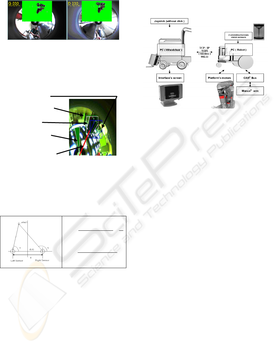
Figure 5: Target Initialisation. Subtraction of the image.
2.2 OmniCAMShift Results
The next figure (Figure 6) shows an example of the
OmniCAMShift application.
Previous Location
Estimated Location
Final Location
Estimated gyration
Computed Angle for
the triangulation
Figure 6: Wheelchair recognition using OmniCAMShift.
Once the wheelchair is identified in the two
omnidirectional images, computing the relative
position of the wheelchair by triangulation (figure 7)
using the two computed angles is easy:
X
tri
= [x
tri
, y
tri
]
T
2)tan()tan(
)tan( d
ab
bd
x
tri
+
−
×
=
)tan()tan(
)tan()tan(
ab
abd
y
tri
−
××
=
Figure 7: triangulation by two bearing angles. The
referential frame is between the two omnidirectional
sensors.
2.3 Evaluation and Clinical Results
As we explained at length, the prototype that we
designed is based on an actual social demand. The
prototype has thus been tested in a hospital.
Unfortunately, the automatic mode, i.e. 1TM:
OmniCamShift was not secure enough (loss of
target) to be used and tested by handicaped people.
The required reliability for wheelchair tracking was
too strict to establish an evaluation with tetraplegic
subjects in clinical conditions. In a first stage we
chose to test the platform with 13 non handicapped
subjects placed in the same constrained motor
conditions as tetraplegic subjects.
Figure 8: Operation’s schema.
However, under laboratory conditions, the
mobile platform was able to follow the wheelchair at
a low speed and at a distance of 2m without any
oscillation in the trajectory (automatic mode). In
order to be manually controlled by the end-user, the
base has to go around the wheelchair automatically
when ordered to, without any prior warning. This
intermediary phase corresponds to the transition
from the automatic mode to the remote-controlled
mode. This transitory trajectory was chosen in a
reliable manner based on obstacle avoidance and the
platform positioned itself without difficulty in front
of the wheelchair in order to start the remote-
controlled operation.
Real-life testing has shown that the end-user will
encounter no difficulties operating the platform. The
main clinical evaluation was dedicated to validate
that the end-user can operate the mobile base + robot
arm as easily when he is seated in the wheelchair as
when he is in bed.
During the grasping operation with a moving
base, the time needed to place the base was not
significantly different between for 5meters near
84sec (standard deviation, s.d. 40) and 9 meters
(105sec s.d. 36). The time needed to accomplish a
grasping task was significantly longer when the
joystick was driven by the chin (108sec s.d. 24) than
by a hand blocked in an orthosis (102sec s.d. 33) or
by a digital device (95sec s.d. 25). The difference in
distance for the grasping action to be undertaken
(between 1, 5 and 9 meters) had a non-significant
impact on the outcome, respectively 56sec s.d. 17;
64sec s.d. 17 and 67sec s.d. 25, with a significant
difference between 1 to 9 meters. With a fixed base
and randomly presented at either 90° or 45° to the
subject, the average time needed to grasp showed a
BIODEVICES 2008 - International Conference on Biomedical Electronics and Devices
12
significant increase between conditions (respectively
61sec s.d. 18 and 141sec s.d. 56). No significant
difference was found during the task combining the
movement of the base and the grasping of an object,
no matter if the patient was in the wheelchair or in
bed, nor if the object was on the ground or on a
table. However, the change in distance from 5
meters to 9 meters increased significantly the
average grasping time from 102sec s.d. 56 to 151
s.d. 80.
In short, the results presented by this research
project show that whether feasible, the time for
grasping with a mobile platform increases
considerably with the distance and with the base
orientation in comparison to the patient place.
Grasping with a mobile robot seems to be a solution
to a wider demand than that originally targeted by
the first studies into the use of robotic assistance. As
there are many people, other than from tetraplegic
people, who are bed-ridden, a far wider target-group
can benefit from the use of robotic assistance.
However, the evaluation also proved that the
wheelchair tracking by a mobile platform had its
limitations and an actual use in an environment
outside of the laboratory is very complicated. This
necessitated the implementation of new software
elements. A part of this future improvement is
discussed in the next part of this article.
3 2TM: KALMAN FILTERING
For solving the problems of target loss presented
above, we add at the previous tracking method
Kalman filtering. That way, we can pinpoint some
detection errors that weren’t detected before
(divergence of the OmniCamShift).
3.1 Problem Formulation
The target, i.e. the wheelchair, located at coordinates
(x
f
, y
f
) in the world frame, moves with a constant
velocity. The state vector is defined by:
[]
T
fff
yxX =
.
The discrete-time state equation for this problem
can be written as:
1
/
111
010
001
++++
++×
⎥
⎦
⎤
⎢
⎣
⎡
=
n
mf
n
m
n
f
n
vXXX
(1)
Where X
m
(n+1)
is defined figure1 and v
(n+1)
is
centred Gaussian white noise v(n+1) ~ (0, Q) with Q
= σ.I
2
, here σ is a scalar and I
2
is the 2x2 identity
matrix. The superscript
f/m
indicates the position of
the wheelchair in relation to the mobile platform.
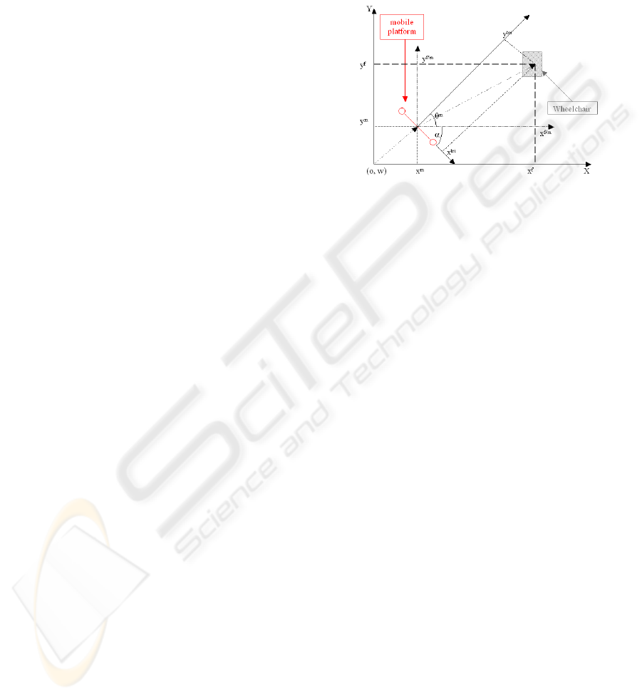
We assume that during the prediction stage the
relative movement between the wheelchair and the
mobile platform remains constant:
i.e. X
f/m
(n+1)
= X
f/m
(n)
. This classical target-
observer geometry is depicted in the figure 9.
Figure 9: Target-observer geometry.
3.2 First Level of Filtering
We use the dead-reckoning data (INS) to compute
the observer state, i.e. our mobile platform state
(step 1: the prediction stage); the non-linear equation
8. Afterwards, the relative position X
tri
of the
wheelchair in connection with our mobile platform
is computed by triangulation (figure 7) of data
provided by the two omnidirectional vision sensors.
The equation (2) enables us to obtain the state
vector
[
]
T
fff
yxX
ˆˆ
ˆ
=
which gives us the position
of the wheelchair in the environment (World frame),
based on the addition of two vectors
m
X
G
and
mf
X
/
G
.
⎥
⎦
⎤
⎢
⎣
⎡
×
⎥
⎦
⎤
⎢
⎣
⎡
−
+
⎥
⎥
⎥
⎦
⎤
⎢
⎢
⎢
⎣
⎡
×
⎥
⎦
⎤
⎢
⎣
⎡
=
⎥
⎦
⎤
⎢
⎣
⎡
tri
tri
m
m
m
f
f
y
x
y
x
y
x
)cos()sin(
)sin()cos(
010
001
ˆ
ˆ
αα
αα
θ
(2)
where :
m
δθα
−°= 90
. The previous vector
[
]
T
fff
yxX
ˆˆ
ˆ
=
is computed outside the filter;
f
X
ˆ
is
used as the measurement in the observation equation
(step 2: update Stage) defined as follow:
n
f
nn
f
wXHX +×=
ˆ
(3)
where w
(n)
is a zero-mean white Gaussian noise.
The observation matrix H
(n)
of the filter becomes
the matrix identity. The observation stage is thus
linear. The diagram below (figure 10) summarises
this process. Some actual results are shortly shown
in the figure 11. This figure represents the position
of our mobile platform and the wheelchair in a real
scenario. The result obtained was satisfactory for a
OMNIDIRECTIONAL VISION TACKING SYSTEM BASED ON KALMAN FILTERING AND OMNICAMSHIFT
13
straight trajectory but insufficient during the phase
where the mobile platform turned, due to errors of
dead-reckoning and the non-repositioning of the
mobile platform. The state vector estimation
f
X
ˆ
is
highly dependant of the of dead-reckoning vector
m
X
G
; thus if an error occurs on
m
X
G
, it appears on
f
X
ˆ
. This method is not efficient.
Figure 10: Filter’s algorithm.
Figure 11: First filter results. (In blue the mobile platform
position, in purple the estimated wheelchair position and
in black the real wheelchair position).
So, to resolve this new problem and to make our
application robuster, we add a second level of
Kalman to this filter, which then deletes this
imperfection. We have named this second filter the
Embedded Extended Kalman Filter (EEKF).
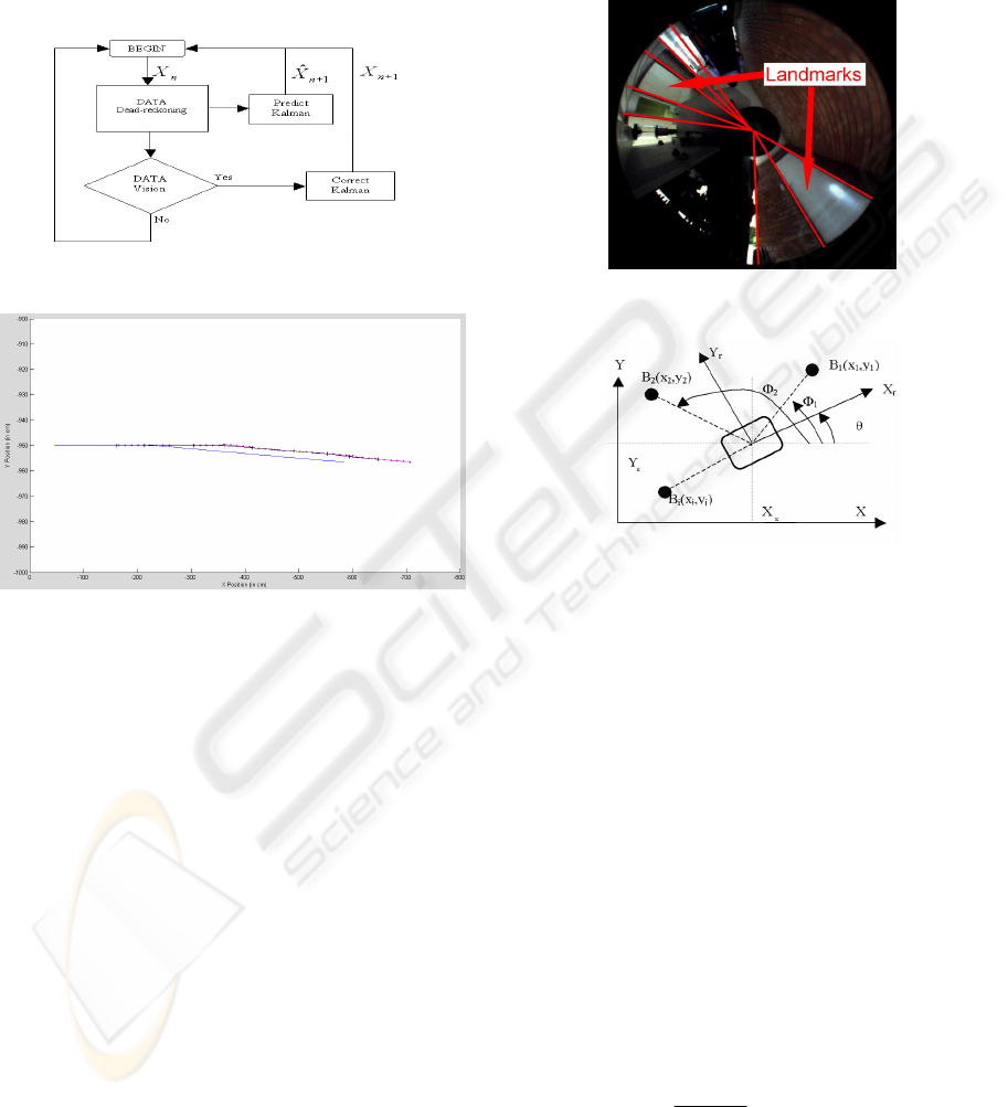
3.3 Second Level: EEKF
We now propose to fully estimate the platform state
vector (“the observer”) by a classical EKF. Thus,
this method requires knowledge of the
environment’s landmarks (EPS). We will be able to
determine, with precision, the position of our mobile
platform and thus be able to re-inject the platform
position in the first Kalman loop.
For indoor application, these landmarks are
walls, doors, objects, angles which one will be able
to detect in an omnidirectional image using
segmentation processing. Therefore, it is necessary
for us to know the map of the environment to be able
to match the omnidirectionnal image primitive to the
known landmarks (doors and windows) of the
environment (see figure 12). In order to extract the
landmarks’ angles of the ominidirectionnal picture,
we compute a Deriche-Canny filter before applying
a classical Hough transform algorithm.
Figure 12: Segmentation and landmarks in an
omnidirectional image.
Figure 13: Relation between landmarks and mobile
platform.
For this process, the equation of observation of the
extended Kalman filter is as follows. The vector of
observation is:
kkk
k
k
k
k
vkXhv
n
z +=+
⎥
⎥
⎥
⎥
⎥
⎥
⎦
⎤
⎢
⎢
⎢
⎢
⎢
⎢
⎣
⎡
= ),(
.
.
2
1
*
τ
τ
τ
(4)
where
τ
k
i , which contains the azimuths angles, is
the layer of i
ème
landmark B
i
of co-ordinates (x
i
, y
i
) i
the world landmark in the moment k. And v
k
is a
measurement noise, presumably white and Gaussian.
The exact position of the beacon B
i
is expressed
according to the state vector X
k
of the system as
follows:
)arctan(
ik
ik
k
xx
yy
i
−
−
=
τ
(5)
The matrix of the Jacobian of the vector function
H is, in the case of measurements of absolute angle:
BIODEVICES 2008 - International Conference on Biomedical Electronics and Devices
14
⎥
⎥
⎥
⎦
⎤
⎢
⎢
⎢
⎣
⎡
−−−−
−−−−
−
=
=
0/)(/)(
...
0/)(/)(
22
2
11
2
11
1/
ˆ
knnkknk
kkkk
H
dxxdyny
dxxdyy
kkk
XX
k
(6)
where d is the distance between the landmark
and the mobile platform.
We add this second Kalman filter before the
correction of the first Kalman filter as can be seen in
the graphic figure 14.
The result of this add-on is a reposition of the
mobile platform in the environment reference (see
figure 13). This better knowledge of the base
location also allows us to have a better estimation of
the wheelchair. Moreover, the update stage of the
first level Kalman filter is now achieved by data
from both the triangulation and the platform location
(second level Kalman filter).
Moreover the errors induced by the dead-
reckoning such as skids and slips, errors of
quantification and others, are taken into account in
an improved way. This improvement stems from our
multi-level Kalman filter that performs a more
accurate location.
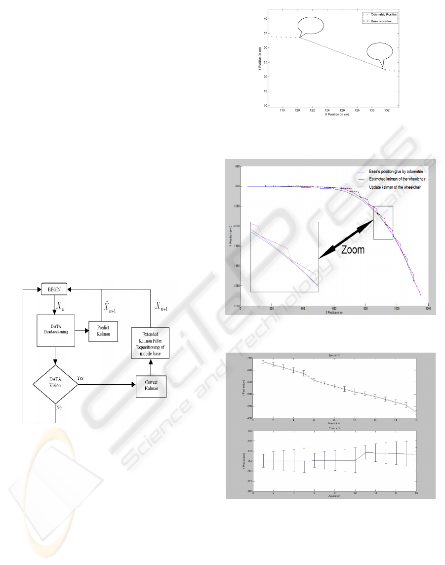
Figure 14: New process of filtering.
We can see that the second filter corrects the
dead-reckoning as seen in figure 15, represented by
the arrow. Here it is a big error because the
wheelchair is suddenly turning.
As we can see in the figure 16, the result of our
process follows the curve well, which our system did
not manage to do before.
Figure 17 shows us the error in X and Y of your
system. These results are given by the matrix of
variance/covariance and allows us to see that our
system tracks the target with the precision as
expected. This way we can confirm the importance
and the need of our second Kalman filter.
A
B
Figure 15: repositioning of the mobile platform. A: dead-
reckoning prediction location; B: EKF estimation.
Figure 16: System in a straight trajectory following in a
curve.
Figure 17: Error of our wheelchair’s system in X and Y.
4 CONCLUSIONS
In this article, we studied a target tracking
application dedicated to an assistive platform for the
disabled. The aim was to track a wheelchair with a
mobile platform mounted with a grasping arm
OMNIDIRECTIONAL VISION TACKING SYSTEM BASED ON KALMAN FILTERING AND OMNICAMSHIFT
15

(MANUS®). We propose an approach based on an
association of two Kalman filtering levels. We have
named this architecture the EEKF. The first level
permits to estimate the wheelchair configuration.
The second is used to compute the mobile platform
configuration in connection with its environment.
We have shown that the second level increases the
precision of the configuration estimation of the
wheelchair in the platform frame. The use of the
identity matrix in the first stage of the Kalman
filtering allows us to solve the problem of the non-
linearity of the system due to the triangulation.
However, our paradigm integrates a strong coupling
of the camshift algorithm and the Kalman estimation
state. This new target tracking approach shows that
it is possible to compensate the loss of tracking by
the camshift, whilst continuing to track.
This paradigm can be considered as a
contribution to solving the problem of TMA (target
& tracker). The robustness of the filtering process is
very important because it is used in a clinical
context. Future works will study the integration of a
supplementary layer based on a particle filter.
Moreover, in this paper we have presented some
original results concerning the clinical tests. These
tests have permitted to evaluate the impact of the
remote controlled mode of this assistive platform.
The results seem to be encouraging. The automatic
mode will also be evaluated in the near future.
REFERENCES
Y. Bar Shalom et T. E. Fortmann, "Tracking and data
association", Academic Press, 1988.
Bar-Shalom Y, Xiao-Rong Li, Multitarget-Multisensor
Tracking: Principles and techniques, 1995.
D.Schulz, W. Burgard, and D. Fox, “People tracking with
mobile robots using sample-based joint probabilistic
data association filters” International Journal of
Robotics Research, vol 22, no. 2, 2003.
Blackman S., Multiple-Target Tracking with Radar
Applications, Artech House, 1986.
B. Marhic, L. Delahoche ,F. de Chaumont, and O. Remy-
Néris, “Robotised Assistance for Persons of Reduced
Mobility: résumé of a project”, ICOST’2006, Ireland.
H. Ishiguro, S. Tsuji “Applying Panoramic Sensing to
Autonomous Map Making a Mobile Robot” in Proc,
Int. Conf. on Advanced Robotics, pp127-132,
November 1993.
G. R. Bradski. Computer video face tracking for use in a
perceptual user interface. Intel Technology Journal,
Q2 1998.
D. Comaniciu and P. Meer. Robust analysis of feature
spaces: Color image segmentation. In International
Conference on Computer Vision and Pattern
Recognition, pages 750-755, San Juan, Puerto Rico, 1997.
C. Cauchois; F. de Chaumont, B. Marhic, L. Delahoche,
M. Delafosse : ”Robotic Assistance: an Automatic
Wheelchair Tracking and Following Functionality by
Omnidirectional Vision”. IEEE/RSJ Int. Conf. on
Intelligent Robots and Systems, (IROS 2005). Pp
:2397 – 2402, 02-06 Aug. 2005.
BIODEVICES 2008 - International Conference on Biomedical Electronics and Devices
16
