
NEUROLAB: A MULTIMODAL NETWORKED EXOSKELETON
FOR NEUROMOTOR AND BIOMECHANICAL RESEARCH
A. F. Ruiz, E. Rocon, F. Brunetti, L. Bueno, J. C. Moreno and J. L. Pons
Bioengineering Group, Instituto de Automatica Industrial, Ctra. Campo Real km 0.200, Madrid, Spain
Keywords:
Biorobotics, Biomechanical Devices, Exoskeletons, Health Monitoring Devices.
Abstract:
NeuroLab refers to an experimental platform designed to enhance studies in human movement and neuro-
motor control. The platform comprises a robotic exoskeleton and some other stand-alone devices. All of
these components have communication capabilities integrated in hardware and can work cooperatively taking
advantage of a networked architecture. A set of experiments have been conducted with NeuroLab. The
objective of the trials was to use mechanical perturbations to identify the viscous-elastic properties in human
elbow joint and to correlate such mechanical impedance with the electromyographic information of muscles
associated to the joint, during a postural task and in a rest position. In each condition, a pseudo-random torque
perturbation was applied directly to the arm and to the forearm by mean of an upper limb powered exoskeleton.
The angular kinematics (velocity and position), kinetics (torque) and the muscular activation patterns (EMG)
in the two main muscles (biceps and triceps brachii) intervening in the elbow flexion-extension movement
were recorded.
1 INTRODUCTION
Human movement and neuro-motor control is a very
complex research field due mainly to the complexity
of the involved mechanisms and the difficult access to
the components of the overall system. Due to these
reasons, the research community tries to exploit all
kinds of valid information (EMG, EEG, kinetics and
kinematics) relating to movement planning and exe-
cution in order to understand this complex system and
to develop new aids in the medical robotics field.
One common and generally-accepted approach to
understanding and modelling the human motor sys-
tem is to monitor and analyse movement-related data
during different motor task. A common approach to
understand the dynamics of the motor control system
is to independently manipulate the mechanical condi-
tions of each joint while acquiring the biomechanical
signals and the generated bio-potentials while the hu-
man motor system adapts to those new applied condi-
tions.
In this scenario, a set of tools attached to the hu-
man body is required. In NeuroLab, there are inde-
pendent devices that communicate with each other,
based on a Personal Area Network (PAN) concept.
Each device has a specific function and helps to ad-
dress the overall goal of the platform. The NeuroLab
integrates several devices in a global architecture. The
main goals of NeuroLab are:
1. Study of human movement in subjects with mo-
tor disorders such as pathological tremor or spas-
ticity. The information provided by the platform
during the execution of specific motor tasks can be
used as a tool to diagnose and assess motor disor-
ders, (Rocon et al., 2007).
2. Study of neuro-adaptative strategies for learning
and training of specific motor patterns through the
application of selected force-fields to the upper
limb. This application could potentially be of con-
siderable impact in patients suffering of cerebral
injuries, (Krebs et al., 1998).
3. Validation of neurophysiological models of hu-
man motor control in upper and lower limbs. This
will help to gain a better understanding of the inte-
gration of the sensory information and the under-
68
F. Ruiz A., Rocon E., Brunetti F., Bueno L., C. Moreno J. and L. Pons J. (2008).
NEUROLAB: A MULTIMODAL NETWORKED EXOSKELETON FOR NEUROMOTOR AND BIOMECHANICAL RESEARCH.
In Proceedings of the First International Conference on Biomedical Electronics and Devices, pages 68-73
DOI: 10.5220/0001049400680073
Copyright
c
SciTePress

lying mechanisms for generation of motor com-
mands.
4. Study of human body behaviour under external
loads. The load application is the basis for several
technical aids to compensate functional disability.
5. Exploration of new communication channels in
human-robot interfaces. This is potentially feasi-
ble through the use of EMG and EEG information
to control wearable robots, (Rosen et al., 2001),
(Pfurtscheller et al., 2002).
6. Assessment and quantification of human upper
limb parameters, e.g. mechanical impedance.
These parameters are considered important for
understanding of the control mechanisms of the
human joints, the generation of control signals,
the execution of movements and the adaptation
under changing conditions.
This paper aims at describing the design and the
development of a platform to enhance research in se-
veral fields. The next section presents each device
concept of the NeuroLab system. Next, a set of ex-
periments which are being conducted with such plat-
form in order to model the human motor control at the
upper limb will be described. The experimental me-
thods and preliminary results are presented in section
3. Finally, the section 4 discusses future work with
NeuroLab.
2 PLATFORM DESCRIPTION
The platform (see figure 1), is composed of modules
and devices that provide several capabilities: an upper
limb robotic exoskeleton, an EMG module, a Biome-
chanical Monitoring module, and an EEG module. It
can further be expanded with other peripherals. A
software platform is defined to manage the system,
e.g. setup the experiments and acquire data. Safety
and reliability were priority considerations in the de-
velopment.
The powered exoskeleton and the devices can
communicate with each other using a CAN-based net-
work and specific protocols. Each element of the plat-
form providesseveralservices which can be requested
by other devices. There are therefore different prim-
itives in the upper layers of the protocol, for instance
to retrieve the data acquired by a module or to control
a joint of the exoskeleton.
The robotic device is an upper limb exoskeleton
which allows the mechanical conditions of each limb
joint to be manipulated independently, (Ruiz et al.,
2006). The networked platform enables combined
Sensors
Actuators
Roboticexoskeleton
EMGModule
EEGModule
Biomechanical
Module
Matlab
Bluetooth
Ethernet
PC/104
ECAN
Wired
Others
Central
Platform
Figure 1: Layout of the NeuroLab system. Different mod-
ules can connect to a base station using Bluetooth. At the
same time, all the modules are part of the wearable-robot
network, called BioNET.
measurement of biomechanical variables (kinemat-
ics and kinetics variables) and biopotentials, such as
electromyography (EMG) and electroencephalogra-
phy (EEG).
2.1 Robotic Exoskeleton
The upper limb robotic exoskeleton in NeuroLab
spans the human elbow and wrist joints, (Rocon et al.,
2007). The sensors (gyroscopes, potentiometers and
force sensors) measure the biomechanics of the arm.
Using this data, limb movements, motor tasks and
several postures can be assessed under different me-
chanical conditions.
Maxon Motor EC 45 Flat continuous current have
been selected as actuation device, which is a very
light, small DC motor without brushes that adapts to
orthotic applications. In order to match the speed and
the torque of the DC motor to the application require-
ments, a gearbox was necessary for the system. This
was done via a harmonic drive. In particular, the drive
selected for the application was the HDF-014-100-
2A. The actuator system configured in this way can
apply a maximum torque of 8 N.m.
The exoskeleton is controlled following an
impedance control strategy which includes a position
feedback loop. The goal of the controller is to modify
the apparent Human–Robot impedance.
NeuroLab has a real-time target computer system
(xPC Target) to control the exoskeleton. Control is
implemented using the MatLab Real-Time suite by
NEUROLAB: A MULTIMODAL NETWORKED EXOSKELETON FOR NEUROMOTOR AND BIOMECHANICAL
RESEARCH
69
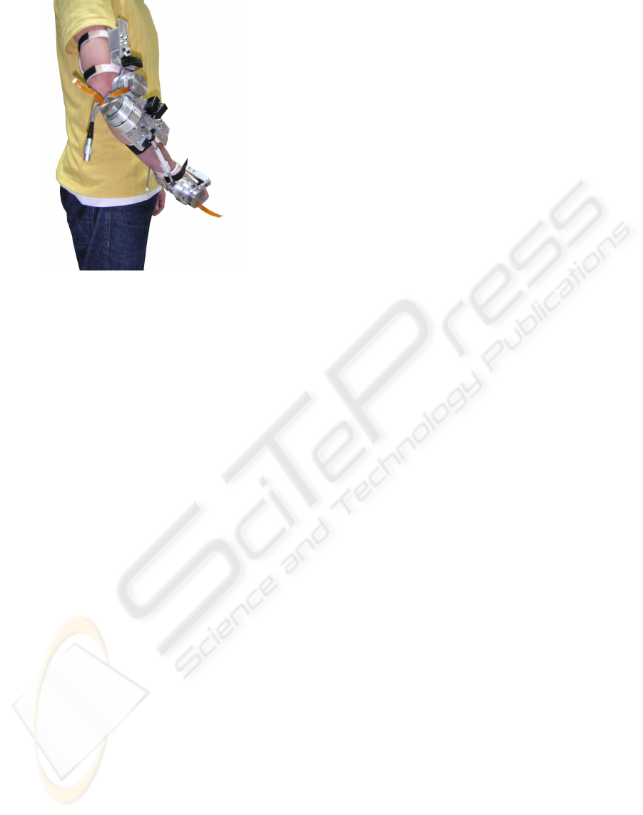
Figure 2: Upper limb robotic exoskeleton. The device spans
the human elbow and wrist joints.
MathWorks, Inc. This environment provides mathe-
matical libraries making it easy to implement control
strategies. The algorithm can be coded in C-language
and compiled in an executable application.
2.2 EMG Module
Measurements supplied by electromyography (EMG)
provide a valuable information regarding physiology
and muscle activation patterns. This information de-
scribes the forces that will be generated by the mus-
cles and the timing patterns of the motor commands.
It can be also used to assess the response of the hu-
man motor system to external dynamic conditions or
perturbations.
The EMG module allows for acquisition of data
on four muscle groups. Since the EMG signal is very
small (50µV- 5mV), it may be affected by interfer-
ence from other biological and environmental noise
sources, e.g. movement artifacts, electric noise and
muscle noise among others, (DeLuca, 1997). In or-
der to minimise the effects of noise, the EMG module
amplifies and filters the raw EMG signals before they
are digitalized.
Additionally, a battery is used to power the EMG
acquisition module in order to reduce 50 Hz har-
monics (power-line noise). In the light of interna-
tional safety regulations regarding electronic devices
connected to human beings, several topics were ad-
dressed in connection with electric isolation of the
EMG module. In particular, galvanic isolation using a
wide-band, unity-gain isolation amplifier was imple-
mented in the EMG Module.
2.3 Biomechanical Monitoring Module
This module uses inertial sensors to acquire kinematic
and kinetic information on the system. This was the
first smart module developed, so further details are
given. The modular approach of NeuroLab enables
the use of the different devices in many different ap-
plications.
The Biomechanical monitoring comprises the fol-
lowing logical components:
• The controller. This uses a TMS320F2812 DSP
Texas Instrument, which is powerful enough to
run all the signal processing algorithms. The
clock frequency is up to 150 MHz. The DSP in-
cludes several communication interfaces.
• The Sensor Set. Two inertial sensors can be con-
nected to the controller using a SPI interface.
Each sensor consists of a set of three gyroscopes,
three accelerometers and three orthogonally-
mounted magnetometers (see figure 3).
• The Data Logging block. An ATMega32 micro-
controller is used to manage a SD card. The
microcontroller implements a FAT16 file system.
Using basic commands, the controller can store
the data of the sensors in a non-volatile memory.
• Communication block. The communication block
includes four different communication interfaces
for networks. The first is the SPI, which is em-
bedded in the DSP and is used to communicate
with the sensors and the data logger. The second
block comprises a Bluetooth module for wireless
communication with a base station for real-time
monitoring. The third interface is a CAN port pro-
vided by the DSP. It can be attached to the Neuro-
Lab BioNET using simple CAN drivers. The last
interface is an USB port for data transfer and real-
time monitoring. The Biomechanical Monitoring
Module can be connected to the central platform
(Figure 1) using Bluetooth or USB.
• Power supply. This is based on an Ion-Lithium
battery with a capacity of 900 mAh. The module
uses the USB connection to charge this battery.
2.4 EEG Monitoring Module
EEG can be used to study movement planning and to
control wearable robots, (Wolpaw et al., 2002). The
development of portable EEG module for research
purposes is not a trivial task. Noisy environments
and movement artifacts affect the quality of the EEG
signals. Moreover, EEG signal processing techniques
are usually complex and require a powerful platform
BIODEVICES 2008 - International Conference on Biomedical Electronics and Devices
70

Figure 3: Inertial sensor that include 3 gyroscopes, 3 ac-
celerometers and 3 magnetometers.
to execute these algorithms. Even relatively simple
algorithms can require a powerful platform as usually
the EEG is acquired using arrays with more than 10
electrodes.
Early developments of EEG Monitoring Module
have been based on a PC/104 computer platform. A
special amplification board was designed following
the safety requirements for devices directly connected
to the human body. This board is aimed to amplify
16 channels with variable gain amplifiers and a band-
width that spans from 0.1 to 80 Hz. The board also
has a notch filter centered on 50 Hz to compensate
for 50 Hz line noise. This board is connected to the
PC/104 through a data acquisition board. The acqui-
sition of the EEG is aimed to use a 512 Hz frequency,
minimizing distortion due to acquisition. The CAN
connectivity is achieved through the use of an exter-
nal CAN board attached to the PC/104 platform.
The EEG monitoring module can provide EEG
logging through the use of a hard drive connected
to the PC/104 board. Other services of the module
comprises the identification of patterns related to the
movement planning and imagination to be used as a
control signal to the robot. This module also uses the
xPC target platform (from MatLab, Inc.) used to con-
trol the robotic exoskeleton. This software platform
was chosen due to the mathematical tools already im-
plemented and for its flexibility.
2.5 BioNET
The purpose of NeuroLab is to integrate several dif-
ferent devices in order to study Human-Robot inter-
action (both cognitive and physical) and the human
neuromotor system using non-invasive techniques. In
view of the wide range of profiles and applications of
the system, a distributed modular approach was se-
lected to implement the proposed concepts.
A network of smart devices was identified as the
optimum solution to achieve the goal. The network is
called BioNET and is CAN-based. The work package
includes the development of several network proto-
cols including service discovery, synchronisation, and
priority management mechanisms among others. A
table describing the device, its services and its param-
eters, is stored in the device itself. This concept is
similar to TEDS, used in IEEE P1451.3.
Current research efforts are aimed to develop the
monitoring and rehabilitation profiles for the network.
3 EXPERIMENTAL METHODS
Many studies have approximated the dynamic be-
haviour of human body segments such as upper
and lower limbs and their joints as a mechanical
impedance, (Hogan, 1984), (Dolan et al., 1993),
(Tsuji et al., 1995), (Zhang and Rymer, 1997). The
mechanical impedance in this context can be defined
as the dynamic relation between small force and po-
sition variations.
Using the platform described, NeuroLab, a set of
experiments are being conducted to estimate the prop-
erties of the human elbow joint impedance and to de-
termine viscoelasticity–EMG relationships. This is
supported for the fact that the EMG information can
be also used to assess the response of the human mo-
tor system to external dynamic conditions or pertur-
bations. In literature, several studies have used elec-
tromyography in biomechanical analysis and human
joint torque estimation, (Clancy and Hogan, 1997).
To start with experiments on this topic, a system
for measuring arm impedance is required. Thus, the
robotic exoskeleton is set up as a mechanical mea-
surement system to get reference measurements for
correlation with EMG–signals. The robotic device
applies torque perturbations to the subject’s arm. Sen-
sors of robotic device deliver the necessary data to
compute the mechanical impedance.
The human arm and their articulations could be
modelled as a mechanical impedance in terms of iner-
tia (I), viscosity (B) and elastic stiffness (K), using a
linear second order model (Equation 1), (Dolan et al.,
1993).
The parameters in the model that represent the dy-
namic behaviour of the human neuromusculoskele-
tal system are non-linear and vary highly depending
on factors such as torque bias and posture, (Kear-
ney and Hunter, 1990). Therefore, experiments that
fit the data to an impedance of a second-order linear-
model must specify an operating point. The operating
point consists of constant posture, constant force, and
non-fatiguing contractions over a particular task. The
ensemble of linear models estimated over a range of
operating conditions may be thought of as defining a
quasistatic model of arm dynamics and can be defined
by the following linear equation:
NEUROLAB: A MULTIMODAL NETWORKED EXOSKELETON FOR NEUROMOTOR AND BIOMECHANICAL
RESEARCH
71

F(t) = I
∂
2
X(t)
∂
2
t
+ B(δ)
∂X(t)
∂t
+ K(δ)X(t) (1)
where F(t) and X(t) represent the force and the dis-
placement, respectively, and δ defines the operating
point of the system.
According to Equation 1, inertial component re-
main constant and viscous and stiffness components
(B and K) are functions.
3.1 Protocol
Four healthy subjects participated in the experi-
ments. Subjects were instrumented with surface EMG
electrodes according to the SENIAM recommenda-
tions, (http://www.seniam.org). Two muscles agonist-
antagonist involved in the elbow joint movement were
measured: the flexor (biceps brachii) and extensor
(triceps brachii long head) muscles.
Subjects wore a robotic exoskeleton on its right
arm allowing elbow flexion and extension in the ver-
tical plane. Shaft joint on the device was aligned with
subject elbow joint, and the device was attached to its
upper arm and forearm. The elbow was flexed making
an angle of 90 degrees.
The trials consisted of an intentional postural task.
In each trial a pseudo-randomtorque perturbation was
applied directly to arm and forearm by the upper limb
powered exoskeleton.
The duration of each trial was 10 seconds. The
subject was asked to maintain the position while the
mechanical perturbation was applied. Three repeti-
tions were chosen for each experimental session and
the signals were sampled at 1 kHz for biomechanical
variables (kinetics and kinematics) and for the elec-
tromyographic signals (sEMG).
3.2 Data Analysis
Kinematics and kinetics data were filtered using a 4
th
order Butterworth low-pass filter with a cut-off fre-
quency of 10 Hz.
The toolbox System Identification Toolbox of Mat-
lab have been used to accomplish the modelling pro-
cess. In particular, the function armax was used to
fits the parameters of the linear second-order model
to the structure of ARMAX (Auto-Regressive Moving
Average with eXogenous inputs), based on a predic-
tion error method.
Surface EMG signals were rectified (full-wave)
and the envelope of the signals extracted using a low-
pass filter with a cut-off frequency of 10 Hz. A 5
th
order Butterworth filter for this purpose was adopted.
The RMS (Root Mean Square) value was used as in-
dex to quantify amplitude of EMG signals as defined
by Equation 2. In the correlation procedure, the RMS
value was the considered variable.
RMS =
s
1
n
n
∑
i=1
x
2
i
(2)
where x
i
is value voltage in i
th
sample, n is number of
samples in segment.
The RMS value represent the root square of the
mean power of the EMG signal for a specific time
period.
The linear equation that relates EMG amplitude
and the variation of angular position to the variation
in the generated torque by the joint might be modelled
as Equation 3.
∆T = I · ∆
¨
θ+ B( ˆs
e
, ˆs
f
) · ∆
˙
θ+ K( ˆs
e
, ˆs
f
) · ∆θ (3)
where ˆs
e
and ˆs
f
are the amplitude estimation of EMG
signals for muscles flexor and extensor, respectively.
∆θ is the variation in angular position and ∆T is the
variation of torque generated by the joint.
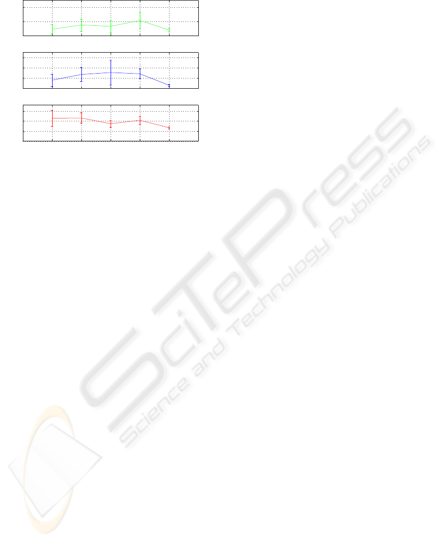
3.3 Results
Figure 4 represents the estimated parameters of me-
chanical impedance and its mean and standard devia-
tion for one subject. Each sample of x-axis in figure
represents a trial, in order to evaluate the repeatabil-
ity. Each trial magnitude was the mean of estimated
values of a set of two-second windows of the recorded
data.
Several quantitative information have been re-
ported in literature mechanical impedance of human
elbow joint, (Zhang and Rymer, 1997). The parame-
ters obtainedin the experiments carried out are similar
to those values.
Correlating EMG–signals with the computed me-
chanical impedance can be considered as a function
of EMG-activity, according to Equation 3. Currently,
this functional relation has being found out.
4 CONCLUSIONS AND FUTURE
WORKS
NeuroLab is based on an upper limb robotic exoskele-
ton with which specific force profiles can be applied.
It establish a real multimodal interaction between the
user and the powered exoskeleton through a set of
BIODEVICES 2008 - International Conference on Biomedical Electronics and Devices
72
0 1 2 3 4 5 6
0
0.2
0.4
Estimated Parameters of Mechanical Impedance
Mean and standard deviation
Inertia
[N.m.s
2
/rad]
0 1 2 3 4 5 6
0
2
4
6
Viscosity
[N.m.s/rad]
0 1 2 3 4 5 6
0
5
10
15
Trial
Stiffness
[N.m/rad]
Figure 4: Mean and standard deviation of estimated param-
eters, for inertia (top), viscosity (middle) and stiffness (bot-
tom).
smart devices. With the networked platform, seve-
ral different experiments can be configured to explore
the human neuromotorsystem and to study the human
movement.
In the platform, there are independent devices that
communicate with each other, based on a Personal
Area Network (PAN) concept. Each device has a spe-
cific function and helps to address the overall goal of
the platform.
The system can be used in a wide range of ap-
plications. The results obtained with NeuroLab pro-
vide valuable information for robotics, modelling of
the human motor system, rehabilitation programs in
health care, training programs and biomechanics.
Lately, several studies are being conducted with
NeuroLab. The experiments presented in the paper
aim to estimate the properties of the human elbow
joint impedance and to obtain the viscoelasticity–
EMG relationships. System identification is achieved
by perturbation analysis, using an external perturba-
tion application that produces changes in the dynam-
ics of system and EMG patterns.
The presented method to estimate the mechanical
impedance of the human arm is suitable to be used
in a clinical setting, e.g., with people with stroke un-
dergoing robotic rehabilitation for a paralyzed arm,
(Palazzolo et al., 2007).
Future work includes a quantitative analysis, pro-
cessing and correlation of the acquired signals (bio-
electric and biomechanical signals), based in Equa-
tion 3. Currently the EEG Monitoring Module is be-
ing validated and integrated in the system presented.
REFERENCES
Clancy, E. A. and Hogan, N. (1997). Relating agonist-
antagonist electromyograms to joint torque dur-
ing isometric, quasi-isotonic, nonfatiguing contrac-
tions. IEEE Transactions On Biomedical Engineering,
44(10):1024–1028.
DeLuca, C. J. (1997). The use of surface electromyography
in biomechanics. Journal of Applied Biomechanics,
13(2):135–163.
Dolan, J. M., Friedman, M. B., and Nagurka, M. L. (1993).
Dynamic and loaded impedance components in the
maintenance of human arm posture. IEEE Transac-
tions on Systems, Man and Cybernetics, 23(3):698–
709.
Hogan, N. (1984). Adaptive control of mechanical
impedance by coactivation of antagonist muscles.
IEEE Transactions On Automatic Control, 29(8):681–
690.
Kearney, R. E. and Hunter, I. W. (1990). System identifi-
cation of human joint dynamics. Critical Reviews on
Biomedical Engineering, 18:55–87.
Krebs, H. I., Hogan, N., Aisen, M. L., and Volpe, B. T.
(1998). Robot-aided neurorehabilitation. IEEE Trans-
action On Rehabilitation Engineering, 6(1):75–87.
Palazzolo, J. J., Ferraro, M., Krebs, H. I., , Lynch, D., Volpe,
B. T., and Hogan, N. (2007). Stochastic estimation
of arm mechanical impedance during robotic stroke
rehabilitation. IEEE Transaction On Neural Systems
and Rehabilitation Engineering, 15(1):94–103.
Pfurtscheller, G., Muller, G., and Korisek, G. (2002). Men-
tal activity hand orthosis control using the eeg: a case
study. Rehabilitation, 41(1):48–52.
Rocon, E., Belda-Lois, J. M., Ruiz, A. F., Manto, M., and
Pons, J. L. (2007). Design and validation of a rehabil-
itation robotic exoskeleton for tremor assessment and
suppression. IEEE Transactions on Neural Systems
and Rehabilitation Engineering, 15(3):367–378.
Rosen, J., Brand, M., Fuchs, M., and Arcan, M. (2001). A
myosignal-based powered exoskeleton system. IEEE
Transaction On Systems, Man and Cybernetics - Part
A: Systems and Humans, 31(3):210–222.
Ruiz, A. F., Forner-Cordero, A., Rocon, E., and Pons, J. L.
(2006). Exoskeletons for rehabilitation and motor
control. In Proceedings of the IEEE International
Conference on Biomedical Robotics and Biomecha-
tronics (BioRob).
Tsuji, T., Morasso, P. G., and Ito, K. (1995). Human hand
impedance characteristics during maintained posture.
Byological Cybernetics, 74(1):475–485.
Wolpaw, J. R., Birbaumer, N., McFarland, D. J.,
Pfurtscheller, G., and Vaughan, T. M. (2002). Brain-
computer interfaces for communication and control.
Clinical Neurophysiology, 113:767–791.
Zhang, L. Q. and Rymer, W. Z. (1997). Simultaneous and
nonlinear identification of mechanical and reflex prop-
erties of human elbow joint muscles. IEEE Transac-
tions On Biomedical Engineering, 44(12):1192–1209.
NEUROLAB: A MULTIMODAL NETWORKED EXOSKELETON FOR NEUROMOTOR AND BIOMECHANICAL
RESEARCH
73
