
AUTOMATIC DEACTIVATION DESIGN FOR PHASED ARRAY
SURFACE PROBE IN 1.5T MRI
Fotios N. Vlachos, Anastasios D. Garetsos and Nikolaos K. Uzunoglu
School of Electrical and Computer Engineering, Narional Technical University of Athens
9 Iroon Polytechniou, 15773, Zografou
Keywords: Automatic tuning, phased array, MR imaging, spectroscopy.
Abstract: We have designed and developed an automatic switching mechanism that deactivates and activates a
reception coil during the MR experiment according to the phase it is at. The mechanism uses a feedback
loop in which a comparator defines whether the current reception signal derives from the RF excitation
pulses or the MR signal and then triggers an analog switch at the back-end of the coil accordingly. We
applied the mechanism on a custom-made four channel phased array probe and tested its functionality by
transmitting RF pulses to the probe of similar length and power to those used in actual MRI systems. The
results presented in this paper demonstrate the robustness of the design and its switching accuracy.
1 INTRODUCTION
In the last ten years there has been much progress in
the development of fully autonomic probes for MR
Imaging and Spectroscopy. In most of the
experimental attempts, emphasis is given on the
automatic tuning and matching (Hwang and Hoult,
1998; Pérez de Alejo et. al., 2004) of the coils in
order to improve the signal-to-noise ratio (SNR)
values and accelerate the initialization procedures
that keep the patient for an extensive period of time
in the MRI bore.
All automatically tuned and matched coils
require being compatible with the pulse sequences
used in the MR experiment, which implies detuning
of the coils during the RF pulse transmission and re-
tuning for the MR signal reception. A series of
complex automatic deactivation techniques have
been developed and tested in the past (Venook et.
al., 2005), which function in parallel with the tuning
and detuning procedures but suffer robustness and
poor results.
The most common deactivation technique that
has been applied in both conventional and
experimental non-automatic configurations is the use
of PIN diodes at the back-end of the probe (Yung et.
al., 2003; Barberi et. al. 2000). These configurations,
however, are totally dependable on the external
signals that the MR scanner supplies in order to turn
on or off the PIN diode.
In this study, we present a simple and robust
automatic design that undertakes the responsibility
of deactivating and activating the probe during the
RF pulse transmission and the MR signal reception
phase respectively. The design does not require the
presence of any external signals and is fully
functionable with a large variety of RF pulse lengths
and powers.
2 MATERIALS AND METHODS
The automatic deactivation circuitry that was
constructed was applied on a prototype human
prostate phased array probe, which we designed and
developed after simulation modelling and
laboratorial measurements.
2.1 Probe Design
The probe is consisted of four rectangular coils of
dimensions 8 × 16 cm and the material that was used
for their construction was copper tape 1 cm wide and
1 mm thick. The coils are distributed into two pairs
of adjacent elements and each pair is positioned
inside an orthogonal shaped conductor frame made
of acetal (Fig. 1A). When a patient is examined the
two frames are locked at a fixed distance so the
elements are placed at the center posterior and
160
N. Vlachos F., D. Garetsos A. and K. Uzunoglu N. (2008).
AUTOMATIC DEACTIVATION DESIGN FOR PHASED ARRAY SURFACE PROBE IN 1.5T MRI.
In Proceedings of the First International Conference on Biomedical Electronics and Devices, pages 160-163
DOI: 10.5220/0001050501600163
Copyright
c
SciTePress
anterior surface of the pelvic area in order to achieve
optimum phased array performance.
Magnetic field and inductance calculations were
carried out using the Biot-Savart integral expression
(Wright and Wald, 1997). The configuration of the
probe was modelled with simulation programming
in order to measure the magnetic field’s intensity in
all three dimensions (Fig. 2A) and calculate the
intensity’s drop percentage at the center of the pelvic
region in comparison to the intensity 1 cm away
from the coils at the surface of the test object. The
theoretical measurements were done for various
distances between the frames of the probe and the
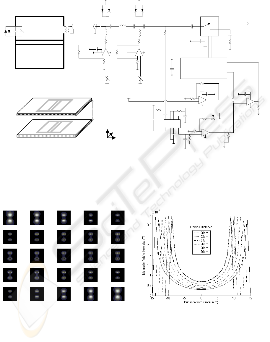
Figure 2: Probe’s theoretical simulation results. (A) Computed magnetic field’s intensity distribution on various xy planes
for frames distance 24 cm. (B) Magnetic field’s intensity at the line that connects the centers of the parallel frames fo
r
various frames distances.
A
B
MRI
Coaxial
Cable λ
4:16 Balun
Coil 1
Coil 2
AD8307
LC
x
C
x
C
y
C
y
Frames
Distance
Coil 1 Coil 2
Coil 3 Coil 4
ZC832
C
1
:RF
1
C
2
:RF
2
+5V
RF
1
RF
2
RF
2
C
2
C
1
+5V
RSW2-25P
+5V
+
-
+
-
+
-
+
-
+5V
+
-
+5V
COMPAR_OUT
DC
+30V
+30V
PIC16F877
(ADC)
Log Detector
Analog Switch (TTL)
ZC832
ADC_VREF
BC
E
D
Threshold
DC
+12V +12V
A
Figure 1: Phased Array probe’s design and circuit diagram. Two pairs of coils are positioned inside two acetal frames (A).
Each coil carries two antiparallel crossed diodes for passive blocking and a variable capacitor for tuning (B). The fine-
tuning/matching circuitries are positioned on four PCBs at λ distance away from the elements. Each PCB includes the
automatic deactivation circuitry that interacts with the probe through a feedback loop. The tuning section (C) uses two pairs
of ZC832 varactor diodes in a pi-network to match the output impedance. The feedback section (D) rectifies the RF pulses
into DC signals, which are then compared to a threshold DC value. The comparator’s output is processed in the
microcontroller (E), which determines when the probe is in the activation and the deactivation phase and controls an analog
switch that connects the probe to the MRI scanner.
y
z
x
AUTOMATIC DEACTIVATION DESIGN FOR PHASED ARRAY SURFACE PROBE IN 1.5T MRI
161
results showed that the drop percentage does not fall
under 7.66% in the worst case scenario of frames
distance 30 cm (Fig. 2B).
The method that was used for the adjacent
elements decoupling was overlapping (Roemer et.
al., 1990). Theoretical calculations with simulation
programming indicated that the distance the adjacent
coils should have in order to minimize the mutual
inductance is 6.7 cm. That translates in 8-6.7=1.3 cm
coils overlap.
The probe is enhanced with a passive blocking
network of two anti-parallel high speed diodes
(Fig. 1B) that behave as a short circuit when they are
forward-biased and serve as a safety precaution for
the rest of the system’s electronics (Noeske et. al.
2000; Zhang and Webb, 2005). 4:16 balun elements
at the back-end of the rectangular loops convert the
balanced output signal of the coils to 50 Ohm
unbalanced. The tuning and the matching of the
probe is manually controlled from a variable non-
magnetic capacitor and 2 pairs of varactors in a pi-
network (Fig. 1C), which lies one wavelength (λ)
away from the coils.
2.2 Automatic Deactivation Design
The function of the MR probe is divided into two
phases: the RF pulse transmission phase, during
which the probe should be deactivated and
disconnected from the MR scanner and the MR
signal reception phase, during which the MR probe
should be activated. The transition of the probe from
the deactivation to the activation phase is controlled
by the automatic deactivation circuitry, which
connects between the probe and the scanner’s
preamplifier. The design of the circuitry is based on
a feedback loop, which uses the probe’s reception
signals to define the phase that it is at.
An analog switch (RSW2-25P) is used to block
the output of the probe from connecting to the MR
scanner, when the RF pulses are transmitted. The
switch is triggered by two signals (C1, C2) that a
microprocessor sends (Fig. 1E). When the C1 signal
is on (activation phase), the RF1 position of the
switch is short-circuited and the scanner receives the
MR signal. Contrarily, when the C2 signal is on
(deactivation phase), the RF2 position is short-
circuited and the high-power transmitted RF pulses
are grounded, protecting the scanner’s preamplifier.
The decision between triggering signal C1 or C2 is
taken from a comparator (LM393AD), which
compares a pre-defined threshold DC voltage with
the output DC signal that is rectified from the
transmitting RF pulses, using a log detector
(AD8307) and two RC low-pass filters (Fig. 1D).
Consequently, when the high power RF pulses are
transmitted, then the output DC signal’s amplitude is
higher than the threshold voltage, the analog switch
is turned off and the probe enters the deactivation
phase (C2 signal triggering). Contrariwise, when the
output DC signal’s amplitude is lower than the
amplitude of the threshold, the analog switch is
turned on and the probe is re-activated (C1 signal
triggering), receiving low power MR signal from the
hydrogen molecules’ resonance.
10μs
10μs
OFFOFF
Outpu
t
ON ON ON
DEACTDEACT ACT ACT ACT
Analog Switch
10μs
10μs
Phase
RF Rectification
DC Threshol
d
Inpu
t
A
B
C
D
E
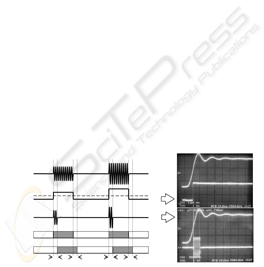
Figure 3: Switching mechanism’s experimental results. (A) Transmitted RF pulses that are used as input to define the
experiment’s phase. (B) DC pulses produced from log detector’s RF rectification (lower line in first combiscope figure).
(C) Analog Switch’s output (lower line in second combiscope figure). 10μs delay was calculated during the switching o
f
the phase. (D) Optimum analog switch’s behaviour following the experiment’s phases. (E) Actual analog switch’s
behaviour with the undesired latency. Upper line in both combiscope figures depicts the trigger that generates the RF pulse.
BIODEVICES 2008 - International Conference on Biomedical Electronics and Devices
162

3 RESULTS
Before the testing of the automatic deactivation
circuitry we tuned and matched the coils of the
probe in the Larmor frequency (63.87 MHz) by
applying an average human pelvic region load on the
frames and adjusting the values of tuning
components. Using the network analyzer
(HP8719D) to measure the reflection coefficient we
managed to drop the S
22
parameter at -55 dB,
keeping the resonance frequency range below 250
KHz, which led to very accurate tuning. The
decoupling between the adjacent elements was also
successful, since the transmission coefficient S
12
drops below -30 dB.
The functionality of the analog switch was tested
in the laboratory using a Signal Generator (HP ESG-
4000A) and a Combiscope (FLUKE PM3380B). RF
pulses of the same power and length with those
transmitted from the MRI system were created in the
Signal Generator and were sent to the probe as input.
The RF pulses varied in length from 2-5 ms and in
power from 5-20 dBm.
The first set of measurements examined the log
detector’s functionality. Specifically, we measured
the DC signal produced from the RF pulse
rectification (Fig. 3B). The resulting DC pulse is
initiated and terminated almost immediately after the
beginning and the end of the signal generator’s RF
trigger respectively. Also, the correspondent DC
pulse’s amplitude is equal to the RF pulse’s
amplitude as expected, allowing accurate
comparison with the DC threshold.
The second set of measurements showed the
output of the probe and verified the turning off and
on of the analog switch during the activation and the
deactivation phase respectively (Fig. 3C). A
potential disadvantage of the method is that there is
an undesired latency of 10 μs in the switching
process that is capable of producing artifacts in the
imaging data (Fig. 3E). The latency is caused mainly
from the processing delays of the microcontroller
that triggers the analog switch and remains constant
without regard to the RF pulse length and power that
is triggered.
4 DISCUSSION
Certain improvements could be applied on the
automatic switching mechanism of the circuitry in
order to overcome the presence of latency in the
function of the analog switch. A way to reduce the
latency is to control the switch directly from the DC
signal that derives from the comparator’s output,
bypassing the time-consuming processing of the
microcontroller.
Also, a practical problem could potentially
appear in the clinical application of the automatic
deactivation circuitry. The probe detunes itself
automatically during the RF pulse transmission and
does not require a decoupling signal from the
scanner. However, many MRI scanners’ protocols
run primary tests on the connected probes by
sending pulse signals in the opposite direction for
software initialization. In that case, the switch would
cause compatibility issues and the probe would not
be recognized by the MR system.
Our prototype automatic deactivation design is a
robust and simplified mechanism that can be applied
on self-tunable MR coils. It was tested in various
conditions and found to be fully functional and able
to switch off or on the probe at all times.
REFERENCES
Hwang, F., Hoult D.I. 1998, Automatic Probe Tuning and
Matching, Magnetic Resonance in Medicine, 39,
pp. 214-222.
Pérez de Alejo, R., Garrido, C., Villa, P., Rodriguez, I.,
Vaquero, J.J., Ruiz-Cabello, J., Cortijo, M., 2004,
Automatic Tuning and Matching of a Small
Multifrequency Saddle Coil at 4.7T, Magnetic
Resonance in Medicine, 51, pp. 869-873.
Venook, R.D., Hargreaves, B.A., Gold, G.E., Conolly,
S.M., Scott, G.C., 2005. Automatic Tuning of Flexible
Interventional RF Receiver Coils, Magnetic
Resonance in Medicine, 54, pp. 983-993.
Yung, A.C., Oner, A.Y., Serfaty, J.M., Feneley, M., Yang,
X., Atalar, E., 2003. Phased-Array MRI of Canine
Prostate Using Endorectal and Endourethral Coils,
Magnetic Resonance in Medicine, 49, pp. 710-715.
Barberi E.A., Gati J.S., Rutt B.K., Menon R.S., 2000. A
Transmit-Only/Receive-Only (TORO) RF System for
High-Field MRI/MRS Applications, Magnetic
Resonance in Medicine, 43, pp. 284-289.
Wright S.M., Wald L.L., 1997. Theory and Application of
Array Coils in MR Spectroscopy, NMR in
Biomedicine, 10, pp. 394-410.
Noeske R., Seifert F., Rhein K-H., Rinneberg H., 2000.
Human Cardiac Imaging at 3 T Using Phased Array
Coils, Magnetic Resonance in Medicine, 44, pp. 978-
982.
Zhang, X., Webb, A., 2005. Design of a Four-Coil Surface
Array for in Vivo Magnetic Resonance Microscopy at
600 MHz, Concepts in Magnetic Resonance Part B,
24B(1), pp. 6-14.
Roemer P.B., Edelstein W.A., Hayes C.E., Souza S.P.,
Mueller O.M., 1990. The NMR Phased Array,
Magnetic Resonance in Medicine, 16, pp. 192-225.
AUTOMATIC DEACTIVATION DESIGN FOR PHASED ARRAY SURFACE PROBE IN 1.5T MRI
163
