
STUDY OF A 4DOF UPPE
R
-LIMB POWE
R
-ASSIST
EXOSKELETON WITH PERCEPTION-ASSIST
Second Stage of Power-Assist
Kazuo Kiguchi and Manoj Liyanage
Graduate School of Science and Engineering, Saga University, 1 Honjomachi, Saga, Japan
Keywords: Power-Assist, Perception-Assist, Exoskeletons, Robots, EMG.
Abstract: As a second stage of the research on power-assist exoskeleton systems, this paper presents a new concept of
an upper-limb power-assist exoskeleton that can assist physically weak persons in performing their daily
activities. The proposed exoskeleton assists not only the motion of the user but also the perception of the
user by using sensors. In the proposed power-assist method, the assisted user’s motion can be modified
based on the environmental information obtained by the sensors if problems are found in the user’s motion.
The effectiveness of the proposed concept is evaluated by performing experiments.
1 INTRODUCTION
Decrease in birthrate and increase of percentage of
aged people are progressing in several countries. In
these societies, the shortage of nursing people has
become a serious problem. Many robotic systems
such as power-assist robots (Kiguchi, et al., 2001-
2007; Rosen, et al., 2001; Kawamoto and Sankai,
2005; Naruse, et al., 2004; Sasaki, et al., 2004;
Guizzo and Goldstein, 2005; Vukobratovic, 1975) have
been proposed to cope with this problem. We have
proposed power-assist exoskeletons to assist the
upper-limb motion of physically weak persons such
as disabled, injured, and/or elderly persons since the
upper-limb motion is important for daily activities.
The conventional exoskeletons only assist the
motion of the user (Kiguchi, et al., 2001-2007). As a
second stage of the research on power-assist
exoskeleton robot systems, this paper proposes a
new concept of an upper-limb power-assist
exoskeleton in order to assist physically weak
persons in performing their daily activities.
In the conventional power-assist exoskeletons,
the motion of the user is supposed to be assisted in
accordance with the user’s motion intention. The
skin surface electromyogram (EMG) is often used to
detect the user’s motion intention (Fukuda, et al.,
2003) since it directly reflects the user’s muscle
activity. Therefore, information of the EMG signals
and/or force sensors is often used to predict the
user’s motion intention in the conventional power-
assist exoskeletons (Kiguchi, et al., 2001-2007).
However, in the case of physically weak persons, the
perception ability is also poor sometimes. For
example, such persons sometimes unknowingly trip
over small obstacles because of their poor perception
ability. Therefore, it is important to assist the
sensing ability of physically weak persons by using
sensors on robotic exoskeletons. Any sensor such as
ultrasonic sensors, infrared sensors, and/or CCD
sensors can be a candidate for the sensors for the
perception-assist.
In the proposed power-assist method, the assisted
user’s motion can be modified based on the
environment information obtained by the sensors if
the exoskeleton detects some problems in the user’s
motion. For example, if the exoskeleton notices that
the user’s hand is going to collide with an obstacle,
an additional assist force including the power-assist
force is provided to the user’s motion in order to
avoid the collision between the user and the obstacle.
On the other hand, the exoskeleton attempts to guide
the user’s hand to an object when the exoskeleton
notices that the user is going to grasp that object, but
his hand is not moving along the correct trajectory.
If the modified motion by the exoskeleton is
different from the user’s intended motion, the
exoskeleton changes its strategy in accordance with
the user’s motion intention. When motion
modification is not required (i.e., when there is no
164
Kiguchi K. and Liyanage M. (2008).
STUDY OF A 4DOF UPPER-LIMB POWER-ASSIST EXOSKELETON WITH PERCEPTION-ASSIST - Second Stage of Power-Assist.
In Proceedings of the First International Conference on Biomedical Electronics and Devices, pages 164-169
DOI: 10.5220/0001050801640169
Copyright
c
SciTePress
problem in the user’s motion), the control method is
the same as the conventional EMG-based power-
assist method (Kiguchi, et al., 2007).
In this study, the proposed power-assist method
is applied to a 4DOF upper-limb power-assist
exoskeleton. The exoskeleton assists shoulder
flexion/ extension, shoulder horizontal flexion/
extension, elbow flexion/ extension, and forearm
supination/pronation motion.
2 UPPER-LIMB POWER-ASSIST
EXOSKELETON
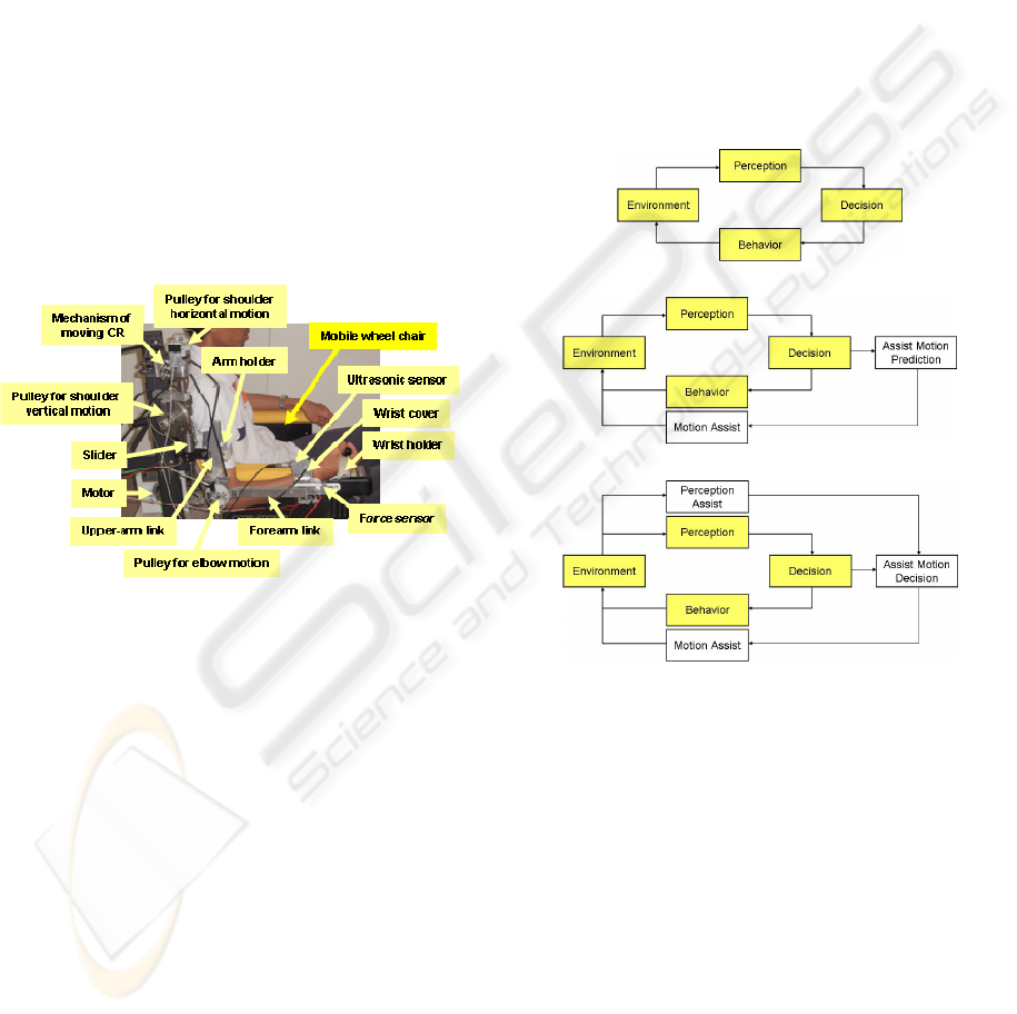
In order to assist 4DOF upper-limb motion, a power-
assist exoskeleton (Fig. 1) was developed (Kiguchi,
et al., 2007). It mainly consists of a shoulder motion
support part, an elbow motion support part, and a
forearm motion support part. The exoskeleton
system can be installed on a mobile wheel chair.
Figure 1: 4DOF upper-limb power-assist exoskeleton.
Usually, the movable range for the human
shoulder is 180º in flexion, 60º in extension, 180º in
abduction, 75º in adduction, 100-110º in internal
rotation, and 80-90º in external rotation. The limit on
the range of forearm pronation-supination motion is
50-80º in pronation and 80-90º in supination, and
that on the elbow flexion-extension motion is 145º in
flexion and -5º in extension. Considering the
minimally required motion in everyday life and the
safety of the user, the shoulder motion of the 4DOF
exoskeleton is limited to 0º in extension and
adduction, 90º in flexion, and 90º in abduction. The
limit on its forearm motion is decided as 50º in
pronation and 80º in supination, and that on the
elbow motion is decided as 120º in flexion and 0º in
extension.
3 POWER-ASSIST WITH
PERCEPTION-ASSIST
In the conventional power-assist robot systems, the
user’s motion intention is estimated in real-time;
subsequently, the estimated motion is assisted by the
power-assist robot systems (Kiguchi, et al., 2001-
2007). However, the perception ability is also
deteriorated sometimes in the case of physically
weak persons. Therefore, there is a possibility of
colliding with an obstacle, tripping over a small
obstacle, or failing to grasp an object even though
the motion is assisted according to the user’s
intention. In this study, the perception of the
environment is also assisted by the exoskeleton.
(a) Human behavior cycle.
(b) Conventional power-assist cycle.
(c) Proposed power-assist cycle.
Figure 2: Power-assist cycles.
The concepts of the human behavior cycle, the
conventional power-assist cycle, and the proposed
power-assist cycle are depicted in Fig. 2 in order to
show the difference among them.
In the proposed power-assist process, when the
user’s motion is not interacting with the environment,
the power assist is the same as the conventional
power assist. Moreover, when the user interacts with
the environment properly, the power-assist method
continues to be the same as the conventional power-
assist method (Fig. 3(a)). However, if the
exoskeleton infers that the user is attempting to grab
an object and the user has miscalculated the position
of the object, motion modification is carried out to
ensure the correct hand trajectory to the object, as
STUDY OF A 4DOF UPPER-LIMB POWER-ASSIST EXOSKELETON WITH PERCEPTION-ASSIST - Second Stage
of Power-Assist
165
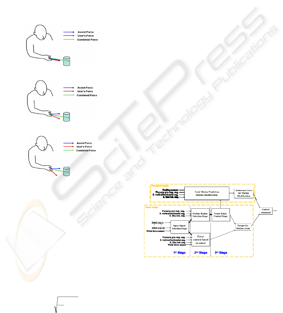
shown in Fig. 3(b). If the modified motion is correct
(i.e., the decision of the exoskeleton is correct), then
the ordinal power assist is performed after the
motion modification, as shown in Fig. 3(a).
However, if the modified motion is wrong (i.e., the
decision of the exoskeleton is wrong), the user
attempts to reject it (sometimes unconsciously) as
shown in Fig. 3(c). This rejection can automatically
be detected by the exoskeleton by monitoring the
user’s EMG signals. Sub sequently, the exoskeleton
changes its strategy, and another motion
modification is carried out in order to avoid a
collision with the object.
(a) Ordinal power-assist.
(b) Motion modification.
(c) Wrong motion modification.
Figure 3: Motion modification.
4 CONTROL METHOD
4.1 EMG
The EMG signals are used as the main input signals
in order to control the exoskeleton in accordance
with the user’s motion intention. Since it is difficult
to use the raw EMG signal as input information for
the controller, the root mean square (RMS) value of
the signal is calculated to extract the feature from the
signal. The equation for the RMS value is written as:
∑
=
=
N
i
i
v
N
RMS
1
2
1
(1)
where v
i
is the voltage value for the i
th
sampling and
N is the number of samples in a segment. In this
study, the number of the sample is set to be 100 and
the sampling time is 500 μsec.
When a certain motion is performed, the EMG
signals of the related muscles show a unique pattern.
Therefore, since the magnitude of the RMS of the
EMG signal indicates the activity level of the
muscles, the upper-limb motion of the user can be
predicted by monitoring the EMG signals of certain
muscles of the user.
In order to predict the 4DOF motion, the EMG
signals from the related muscles of 12 locations are
measured in this study (Kiguchi, et al., 2001-2007).
4.2 EMG-Based Control
The basic architecture of the controller is depicted in
Fig. 4. The controller basically consists of a power-
assist part and a perception-assist part. The power-
assist part consists of three stages (first stage: input
signal selection stage; second stage: posture region
selection stage; and third stage: neuro-fuzzy control
stage). This power-assist part is basically the same
as the conventional EMG-based controller (Kiguchi,
et al., 2007). In the first stage of the power-assist
part, the EMG-based control or the wrist-sensor-
based control is applied in accordance to the muscle
activity levels of the user. In the second stage of the
power-assist part, proper neuro-fuzzy controllers are
selected according to the shoulder and elbow angle
regions. In the third stage of the power-assist part,
the torque required for each joint motion assist is
calculated by using the selected neuro-fuzzy
controllers.
Figure 4: Controller architecture.
In the perception-assist part, the sensor
information and the estimated user’s motion
intention (the output of the neuro-fuzzy controllers)
are used to decide the motion to be modified in this
part. Sensors such as ultrasonic sensors, infrared
sensors, and/or CCD sensors can be used to detect
the objects in the environment. In this study, an
BIODEVICES 2008 - International Conference on Biomedical Electronics and Devices
166
ultrasonic sensor [FW-H10R, Keyence] is applied to
detect the objects.
The force vector of the assisting motion at the
user’s hand can be calculated on the basis of the
estimated torque (the output of the neuro-fuzzy
controllers) from the EMG signals in the third stage
of the power-assist part. Since the estimated force
vector contains noise and an estimated error, it is
averaged with the estimated force vector data in the
past. The relationship between the force vector at the
user’s hand and the joint torque vector of the user’s
upper-limb is written as:
τ
T
JF
−
=
(2)
where F is the force vector at the user’s hand
(averaged by using the past data), τ is the joint
torque vector of the user’s upper-limb, and J is the
Jacobian matrix. The estimated force vector of the
user directly indicates the user’s motion intention.
4.3 Perception-Assist with Ultrasonic
Sensor
When a user is moving his/her arm toward an object
in order to grab it, the trajectory of the hand (tip of
the arm) is the almost a straight line toward the
object (Flash and Hogan, 1985). Therefore, the
change in the distance of the tip of arm and the
reduction in the distance between the tip of arm and
the object are supposed to be the same. The change
in the distance of the tip of arm is calculated by
using the kinematics of the exoskeleton. The
reduction in the distance between the hand and the
object is calculated by using the ultrasonic sensor.
When the arm is moving toward the object, these
two values come close to each other but vary in a
particular range. This range is determined based on
the experimental results. It is important to select this
range to be as narrow as possible in order to identify
the trajectory of the arm more accurately.
If the exoskeleton identifies that the trajectory
required for the user is different from the current
user’s trajectory, then the exoskeleton attempts to
modify the trajectory by applying an additional force
at the tip of the arm. If the estimated force vector at
the user’s hand is changing to the modified
trajectory, the exoskeleton assumes that the motion
modification strategy as correct. If the user’s hand is
moving along the correct trajectory to grab the
object, no motion modification is provided to the
user’s motion. However, if the estimation force
vector at the user’s hand is changing to a direction
opposite to the motion modification direction, the
exoskeleton assumes that the motion modification
strategy is not correct and attempts to determine
another possibility. If the exoskeleton can not
determine another possibility, then it simply
performs the conventional power-assist.
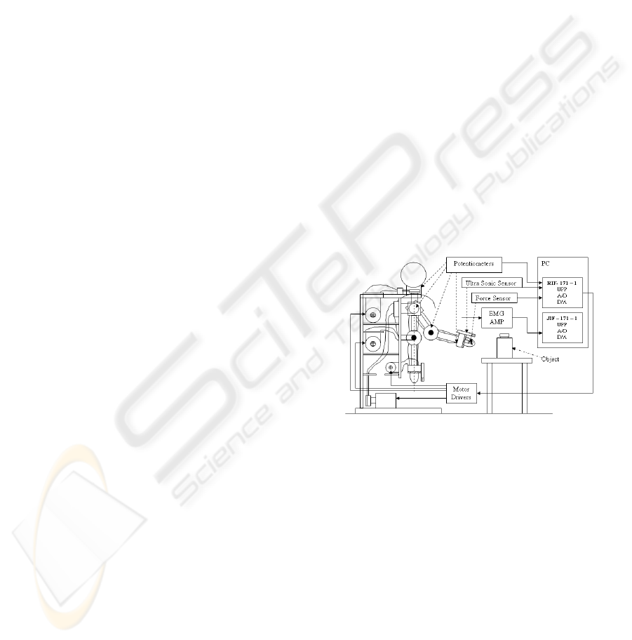
5 EXPERIMENT
The experimental set-up is shown in Fig. 5. As
shown, a plastic bottle was used as the object. In the
experiment, upper-limb motion was performed
toward the object. Two interface boards (RIF–171–1
and JIF–171–1) are used to process the A/D
operations of potentiometer signals, force sensor
signals, EMG signals, and ultrasonic sensor signals
and also to process the D/A operations required to
send the calculated torque commands back to the
motor drivers to control the motors. The measured
EMG signals are amplified by the EMG amplifier
before sending them to the interface board. The
motor torque commands are calculated in the PC and
then sent to the four motor drivers to operate four
motors. The output of the ultrasonic sensor is sent to
the RIF–171–1 interface board and then processed
with the same frequency as the other signals (i.e.,
2,000 Hz frequency).
Figure 5: Experimental setup.
Three kinds of experiments were performed on
the same subject in order to evaluate the
effectiveness of the perception-assist. In the first
experiment, the subject attempted to move the hand
toward the object to grab it along the correct hand
trajectory. In the second experiment, the subject also
attempted to move the hand toward the object to
grab it, but deliberately along a wrong trajectory. In
the third experiment, the subject attempted to move
the hand forward to avoid colliding with the object.
In this experiment, a wrong trajectory (i.e., the
trajectory for which the hand collides with the
object) is generated deliberately.
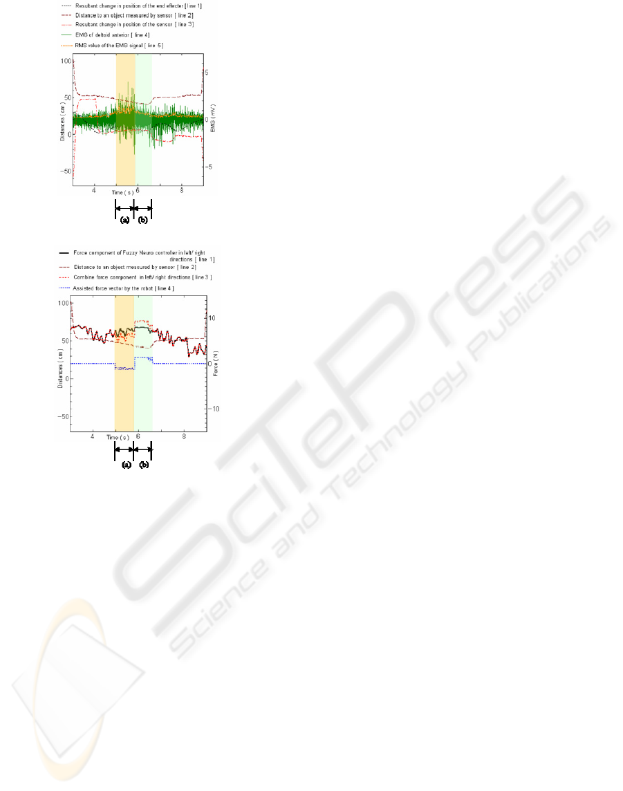
Figure 6 shows the results of the first experiment.
The hand trajectory determined by the exoskeleton,
the distance to the object measured by the ultrasonic
STUDY OF A 4DOF UPPER-LIMB POWER-ASSIST EXOSKELETON WITH PERCEPTION-ASSIST - Second Stage
of Power-Assist
167
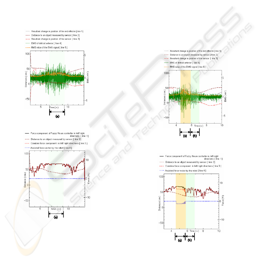
sensor, the change in the position of the sensor, the
raw EMG signal of the deltoid – anterior part, and
the RMS value are shown in Fig. 6 (a). The
estimated force vector at the user’s hand (calculated
from the output of the neuro-fuzzy controllers), the
combined force vector (modified force vector), the
assisted force vector (additional force for the motion
modification), and the distance to the object
measured by the ultrasonic sensor are shown in Fig.
6 (b). These experimental results show that the
exoskeleton effectively performs the power-assist
(conventional power-assist) on the basis of the user’s
motion intention, when there are no problems in the
user’s motion.
(a) EMG signal.
(b) Motion modification.
Figure 6: Experimental results of the first experiment.
Figure 7 shows the results of the second
experiment. During the interval (a) in Fig. 7, the
motion modification was performed to change the
trajectory of the user’s hand to the correct trajectory
to proceed toward the object since the exoskeleton
determined that the hand trajectory of the user is
different from the estimated one. Since the decision
of the exoskeleton was correct, the ordinal power-
assist (power-assist without any motion
modification) was performed until the user grasped
the object (the interval (b)) after that.
Figure 8 shows the results of the third
experiment. During the interval (a) in Fig. 8, the
motion modification was performed to change the
trajectory of the user’s hand to a trajectory leading to
the object since the exoskeleton determined that the
trajectory of the user’s hand was different from the
estimated one. During the interval (b) in Fig. 8, the
exoskeleton determined that its strategy was wrong
and changed it to modify the trajectory of the user’s
hand to avoid a collision with the object. Since the
second decision of the exoskeleton was correct, the
ordinal power assist (power assist without any
motion modification) was performed.
(a) EMG signal.
(b) Motion modification.
Figure 7: Experimental results of the second experiment.
These experimental results show the
effectiveness of the proposed power-assist method
with perception-assist.
BIODEVICES 2008 - International Conference on Biomedical Electronics and Devices
168
(a) EMG signal.
(b) Motion modification.
Figure 8: EMG of elbow biceps (short head) with power
and perception assist.
6 CONCLUSIONS
A new concept of a power-assist exoskeleton that
assists not only the motion but also the perception of
the user by using sensors is proposed. In the
proposed power-assist method, the user motion is
modified by the exoskeleton if it is necessary,
although the conventional power-assist robot never
modifies the user motion. The effectiveness of the
proposed power-assist exoskeleton was verified by
performing experiments.
ACKNOWLEDGEMENTS
The authors gratefully acknowledge the support
provided for this research by Japan Society of
Promotion of Science (JSPS) Grant-in-Aid for
Scientific Research (C) 19560258.
REFERENCES
Flash, T., Hogan, N., 1985. The coordination of Arm
Movements: An Experimental Confirmed
Mathematical Model, Journal of Neuroscience, vol.5,
pp.1688-1703.
Fukuda, O., Tsuji, T., Kaneko, M., Otsuka , A., 2003. A
Human-Assisting Manipulator Teleoperated by EMG
Signals and Arm Motions, IEEE Trans. on Robotics
and Automation, vol. 19, no. 2, pp.210-222.
Guizzo, E., Goldstein, H., 2005. The Rise of the Body
Bots”, IEEE Spectrum, vol.42, no.10, pp.42-48.
Kawamoto, H., Sankai, Y., 2005. Power Assist Method
Based on Phase Sequence and Muscle Force Condition
for HAL, Advanced Robotics, vol.19, no.7, pp.717-
734.
Kiguchi, K., Esaki, R., Fukuda, T., 2005. Development of
a Wearable Exoskeleton for Daily Forearm Motion
Assist, Advanced Robotics, vol.19, no.7, pp.751-771.
Kiguchi, K., Imada, Y., Liyanage, M., 2007. EMG-Based
Neuro-Fuzzy Control of a 4DOF Upper-Limb Power-
Assist Exoskeleton, Proc. of 29
th
Annual International
Conf. of the IEEE Engineering in Medicine and
Biology Society.
Kiguchi, K., Iwami, K., Yasuda, M., Watanabe, K.,
Fukuda, T., 2003. An Exoskeletal Robot for Human
Shoulder Joint Motion Assist, IEEE/ASME Trans. on
Mechatronics, vol.8, no.1, pp.125-135.
Kiguchi, K., Kariya, S., Watanabe, K., Izumi, K., Fukuda,
T., 2001. An Exoskeletal Robot for Human Elbow
Motion Support – Sensor Fusion, Adaptation, and
Control, IEEE Trans. on Systems, Man, and
Cybernetics, Part B, vol.31, no.3, pp.353-361.
Kiguchi, K., Tanaka, T., Fukuda, T., 2004. Neuro-Fuzzy
Control of a Robotic Exoskeleton with EMG Signals,
IEEE Trans. on Fuzzy Systems, vol.12, no.4, pp.481-
490.
Kiguchi, K., Yamaguchi, T., Sasaki, M., 2006.
Development of a 4DOF Exoskeleton Robot for
Upper-limb Motion Assist, Proc. of 2006 ASME/JSME
Joint Conf. on Micromechatronics for Information and
Precision Equipment, S10_03.
Naruse, K., Kawai, S., Yokoi, H., Kakazu, Y., 2004.
Design of Wearable Power-Assist Device for Lower
Back Support, Journal of Robotics and Mechatronics,
vol.16, no.5, pp.489-496.
Rosen, J., Brand, M., Fuchs, M., Arcan, M., 2001. A
Myosignal-Based Powered Exoskeleton System, IEEE
Trans. on System Man and Cybernetics, part A, vol.
31, no. 3, pp. 210 - 222.
Sasaki, D., Noritsugu, T., Takaiwa, M., 2004.
Development of Wearable Power-Assist Device for
Lower Back Support, Journal of Robotics and
Mechatronics, vol.16, no.5, pp.497-503.
Vukobratovic, M., 1975. Legged Locomotion Robots and
Anthropomorphic Mechanisms, Mihailo Pupin
Institute, Belgrade.
STUDY OF A 4DOF UPPER-LIMB POWER-ASSIST EXOSKELETON WITH PERCEPTION-ASSIST - Second Stage
of Power-Assist
169
