
NOVEL CONTROLLER FOR REBREATHER DIVING SYSTEMS
True Sensor Signal Validation and Safe Oxygen Injection
A. Sieber
1,2
, B. Koss
2
, R. Bedini
3
, K. Houston
2
, A. L’Abbate
2
and P. Dario
2
1
Profactor Research and Solutions GmbH, Seibersdorf, Austria
2
Scuola Superiore Sant’Anna, Pisa, Italy
3
CNR, Istituto di Fisiologia Clinica, Pisa, Italy
Keywords: Rebreather, eCCR, mCCR, oxygen injection, pO
2
sensors, Oxygen, diving.
Abstract: In electronically controlled closed rebreather diving systems the partial pressure of oxygen (p O
2
) inside the
loop is controlled with 3 pO
2
sensors, a microcontroller and a solenoid valve, critical components that are
prone to fail. State of the art failure detection integrated in rebreather diving systems for recreational
purposes does not offer the necessary reliability required for life sustaining systems. The present paper
describes a novel controller that combines true sensor signal validation with safe oxygen injection.
1 INTRODUCTION
In the past 30 years, underwater activities have
registered a steep increase across Europe, going
from few thousands of people in the 1980s, when
diving was prevalently an elite activity, to 1.000.000
in 1990s, with scuba and apnoea EU divers engaged
in diving activities worldwide (Divers Alert
Network, 1992). Today about five million EU
people are practicing diving activities. With an
increasing number of divers also the diving industry
is growing, presenting a continuous need for
research and development in the field of recreational
diving.
1.1 Open Circuit Diving
The breathing gas providing part of typical open
circuit diving equipment for recreational purposes
consists of a gas storage tank (typically 10 – 18l, 200
bar) and a two stage pressure regulator (SCUBA)
(U.S. Navy Diving Manual, 2005), (NOAA Diving
Manual). The first stage reduces the tank’s pressure
to a intermediate pressure around 8-10 bar higher
than ambient pressure. The second stage, also known
as the regulator, reduces the intermediate pressure to
ambient pressure thus allowing the diver to breath
underwater. Exhaled air is then vented through an
exhaust valve into the water.
The maximum time a diver can stay under water
is mainly determined by the amount of gas he is
carrying with him, the depth, and the breathing
volume per minute. So what is the gas efficiency of
open circuit diving?
A normal relaxed diver metabolizes
approximately 0,8 to 1 bar l /min O
2
(Noaa, Navy).
This O
2
consumption may increase up to 2,5 to 3,5
bar l / min in the case of hard physical activities. As
an example: A diver has a typical surface breathing
minute volume of 25 bar l / min. This volume
contains approximately 5,25 bar l O
2
. But only 0,8
bar l are metabolized – means only 0,8 l of the 25 l
are really needed. This results in a gas efficiency of
approximately 3%. As the pressure increases with
depth, this ratio decreases. At 40 m our example
diver breathes now at 40 m again 25 l /min, but due
to the increased ambient pressure (5 bar now instead
of 1 bar at the surface), the consumed gas is 125
bar/l min. The O
2
metabolism is still the same 0,8
l/min, so the gas efficiency at 40 m drops to
approximately 0,6 %. A tank with 10l volume, 200
bar pressure contains in this case enough gas for a
period of 16 minutes. Besides the low efficiency,
open circuit diving has additional drawbacks like
very cold (due to expansion the gas is cooled) and
dry (compressed air contains only a negligible
amount of humidity) breathing gas and relatively
high weight (~20kg for a 10l tank including the
regulator and the buoyancy compensating jacket).
44
Sieber A., Koss B., Bedini R., Houston K., L’Abbate A. and Dario P. (2008).
NOVEL CONTROLLER FOR REBREATHER DIVING SYSTEMS - True Sensor Signal Validation and Safe Oxygen Injection.
In Proceedings of the First International Conference on Biomedical Electronics and Devices, pages 44-49
DOI: 10.5220/0001051000440049
Copyright
c
SciTePress
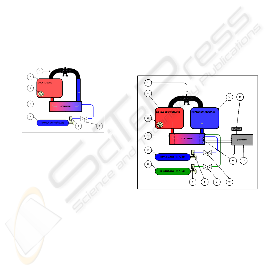
1.2 Rebreathers
A solution to increase the gas efficiency is using a
rebreather, where the diver breathes in a loop instead
of venting the exhaled gas into ambient. In a
rebreather (figure 1 shows the schematics of an
oxygen rebreather) (U.S. Navy Diving Manual,
2005) the diver exhales in a bag – the so called
counter lung. A scrubber removed carbon dioxide
and fresh gas is added to substitute metabolized O
2
.
This recycled gas is then inhaled by the diver again.
In the case of a pure O
2
rebreather, the loop contains
mainly O
2
. The partial pressure of O
2
(pO
2
) inside
the loop is dependent on the depth, for example 1
bar at the surface and 2 bar in 10 m depth (each 10
m of depth the ambient pressure is increased by 1
bar). Such a rebreather has the advantages of
maximized gas efficiency, bubble free and silent
diving and warm and humid breathing gas.
Figure 1: Schematics O
2
rebreather (1: mouthpiece, 2:
counterlung, 3: overpressure valve, 4: scrubber, 5:oxygen
tank, 7: manual valve).
The absolute pO
2
limits for a live sustaining
breathing gas is 0,1 bar as the lower limit and 1,6 bar
as maximum. A pO2 above this limit may lead to a
oxygen intoxication, which can result in an epileptic
fit like convulsion. In such a case the diver will
loose his mouthpiece, drown and die. A pO
2
lower
than 0,1 bar will lead to unconsciousness (Mount,
T., Gilliam, B., Bohrer R., Taylor, L., Sommers,
L.H., Crea, J., Nordsteam, R., 1992), (Ehm, O.F.,
Hahn, M., Hoffmann, U., Wenzel, J., 1996).
The maximum pO
2
limit of 1,6 bar sets the depth
limit for pure O
2
rebreathers to 1,6 m and are
normally used for military applications. Rebreathers
used for recreational purposes are mostly either semi
closed rebreathers (SCR) or manually or
electronically controlled completely closed
rebreathers (mCCR or eCCR).
In an SCR O
2
enriched air is being brought in the
loop via a constant flow injector (commonly a
orifice, typically 6 – 12 bar l / min) from tank to
substitute the metabolized O
2
. Every 4th or 5th gasp
excessive gas is then vented through an overpressure
valve. The maximum depth for SCR’s is mainly
limited by the percentage of O
2
in the supply gas.
In a mCCR or an eCCR the pO
2
is usually kept
at constant level (Dederichs, H., Floren, G.,
Waldbrenner, M., Wilhelm, R., 2004), only the
metabolized O
2
is substituted. To avoid the depth
limit of 1,6 m of pure O
2
rebreathers, the breathing
gas in a closed rebreather contains also N2 or He
(He or He N
2
mixtures for deeper dives, normally
known as technical dives).
To be able to keep the pO
2
at a constant level, a
kind of regulation loop is needed (Straw, P.E.,
2005). Therefore electrochemical oxygen sensors,
whose output signal is proportional to the partial
pressure of O
2
, are used as sensing elements. In a
mCCR the diver reads the pO
2
from a display
(Baran, U., Frost, A.J., 2004) and if needed adds O
2
manually. In an eCCR this regulation task is usually
performed with a microcontroller and a solenoid
valve.
Figure 2: Schematics eCCR (1: mouthpiece, 2: exhale
counterlung, 3: overpressure valve, 4: scrubber, 5: oxygen
tank, 6: diluent tank, 7,8: pressure regulators, 9: manual
diluent vlave, 10: solenoid, 11: pO
2
sensors, 12 µ-
processor, 13: inhale counterlung, 14: display).
The regulation of the pO
2
inside the loop
depends on the pO2 sensor signal. Unfortunately
these electrochemical sensors are not reliable
components and have a short life time of
approximately 1 year in use. Typical problems that
may occur are:
- non linearity
- current limitation (the output signal of the
sensor is limited above a certain pO2)
- sensor failure
NOVEL CONTROLLER FOR REBREATHER DIVING SYSTEMS - True Sensor Signal Validation and Safe Oxygen
Injection
45
The consequence of a sensor failure may be a
deviation of the pO
2
inside the loop, wich can be life
threatening.
State of the art method to solve this problem is to
use three pO
2
sensors instead of one (Deas, R.A.,
Evtukhov, M.V., 2003). If one sensor signal differs
from the others, the sensor signal is “voted out”
(voting algorithm) (Parker, M., 2005). Sensors of the
same production lot and the same age often show the
same failures at the same time. Problems that occur
because of wrong but similar sensor signals of at
least two sensors can still not be detected because
the voting algorithm will not work in this case as
“voting” does not offer a real sensor signal
validation.
Another weak point in commercial available
eCCR systems is the oxygen injection. Usually a
solenoid valve is deployed for this task. Failures that
may appear are that either the valve does not open
anymore (defect in the solenoid or the electronics) or
that it is stuck open (for example because of dirt). A
valve that is stuck open will allow a free flow of O
2
that will lead in a short period of time to a life
threatening pO
2
inside the loop. A solution, that can
be found in eCCR for military applications is to use
multiple solenoids for redundancy. In fact in
recreational rebreathers this is still not state of the
art.
The present paper describes a eCCR
controller, that allows on the one hand a true
sensor signal validation and on the other hand is
equipped with a novel sensorized oxygen
injection mechanism, that, in case of a failure,
does not allow an O
2
free flow and enables
reliable failure detection.
This eCCR controller enabled the development
of a small and lightweight eCCR prototype for
recreational proposes. It will be detailed in the
section results.
2 METHODS
2.1 pO
2
Sensor Signal Validation
As described above, the state of the art voting
algorithm does not provide a real sensor signal
validation as it is based just on a comparison of the
output signals of the sensors. A novel sensor signal
validation procedure was developed to confront this
problem.
The principle is based on injection of a gas with
a known pO
2
in front of the pO
2
sensor membrane.
With the help of another solenoid, gas from the
diluent tank can be injected directly in front of the
membrane of the oxygen sensors. With an orifice of
140 µm diameter the maximum flow is restricted to
2 bar l / min. Within an injection time of 5 s the pO
2
sensor signals should drop to the value
corresponding to the pO
2
of the injected gas, which
is given by the O
2
percentage of the diluent gas and
the ambient pressure. A comparison of the sensor
signal and the calculated reference signal allows
then a reliable sensor signal validation and failure
detection.
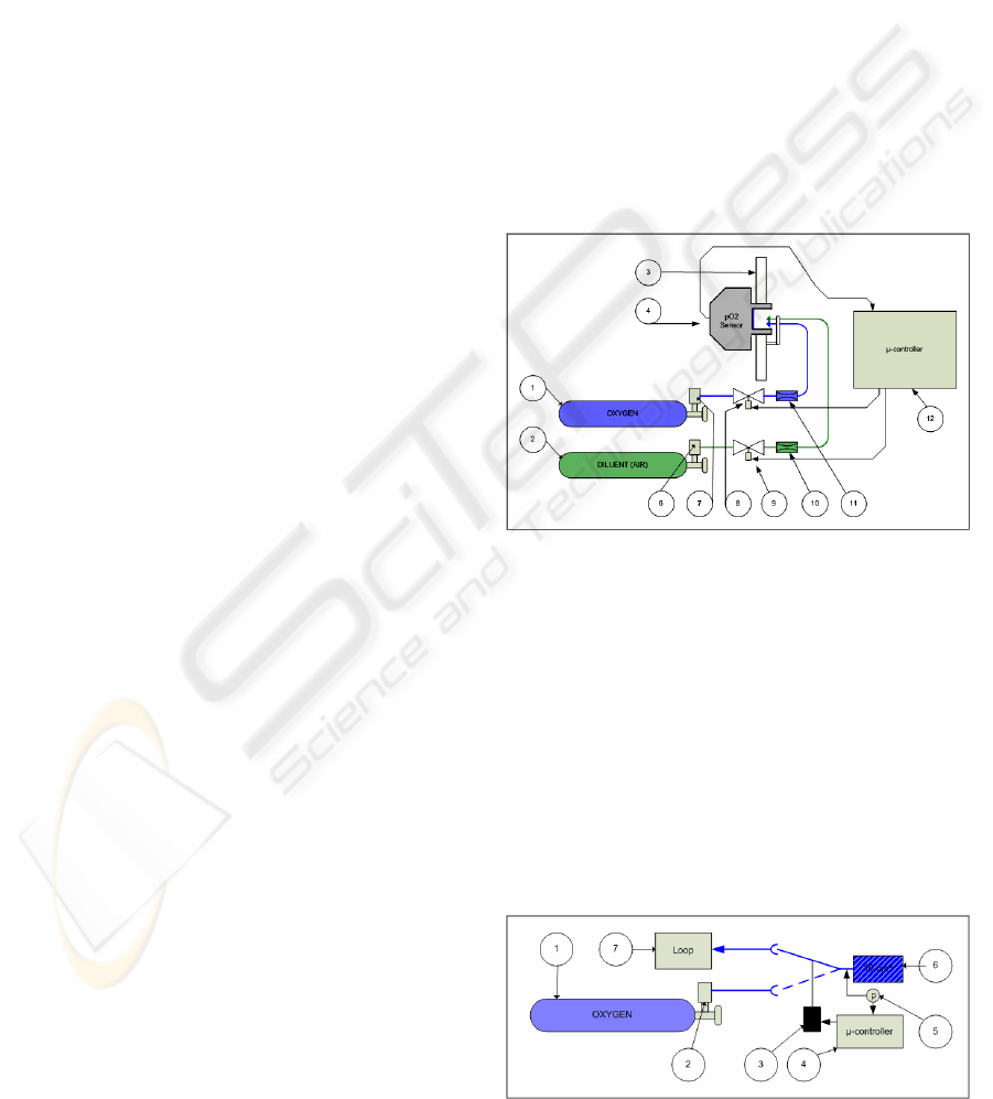
Figure 3a shows an enhanced version of the sensor
signal validation apparatus, where it is not only
possible to inject diluent gas in front of the sensor
membrane but also pure O
2
, to test the sensor for
current limitation and linearity at preferable a depth
between 6 and 10m. It has to be remarked that due to
the small flow of just 2 bar l / min, the functionality
of the rebreather is not negatively affected.
Figure 3a: The principle schematics of our true pO
2
sensor
signal validation (1: oxygen tank, 2: diluent tank, 3: sensor
support, 4: pO
2
sensor, 6,7: pressure regulators, 8,9:
solenoids, 10,11: flow restriction orifices, 12
microcontroller).
2.2 Safe O
2
Injection
The metabolized O
2
has to be replaced by fresh O
2
from the tank. Therefore usually in eCCR a solenoid
is controlled by a microcontroller as schematically
displayed in figure 2. To confront the problems like
a stuck solenoid valve, we invented a novel pO2
injection mechanism, displayed schematically in
figure 3b.
Figure 3b: Safe O
2
Injection.
BIODEVICES 2008 - International Conference on Biomedical Electronics and Devices
46
O
2
is supplied from an oxygen tank (figure 3b).
The pressure is then reduced with a oxygen
compatible standard SCUBA fist stage (2) to a
intermediate pressure of 10 bar over ambient.
Instead of the state of the art 2/2 solenoid used for
oxygen injection, a 2/3 version (3) is deployed.
When powered though the microcontroller (4), the
reservoir (6) is filled with 0,1 bar l O
2
. When the
solenoid is switched off, the gas in the reservoir is
injected into the loop (7). To monitor the injection
and detect reliably a failure, a pressure sensor is
integrated (5) (the pressure of the successfully filled
reservoir should be like the intermediate pressure 10
bar over ambient).
A failure of the solenoid (stuck open or closed)
will not result in a free flow of O
2
. A second benefit
is that due to the design with a reservoir every O
2
injection will provide exactly 0,1 bar l of O
2
. This
allows an easy calculation of the O
2
metabolism of
the diver.
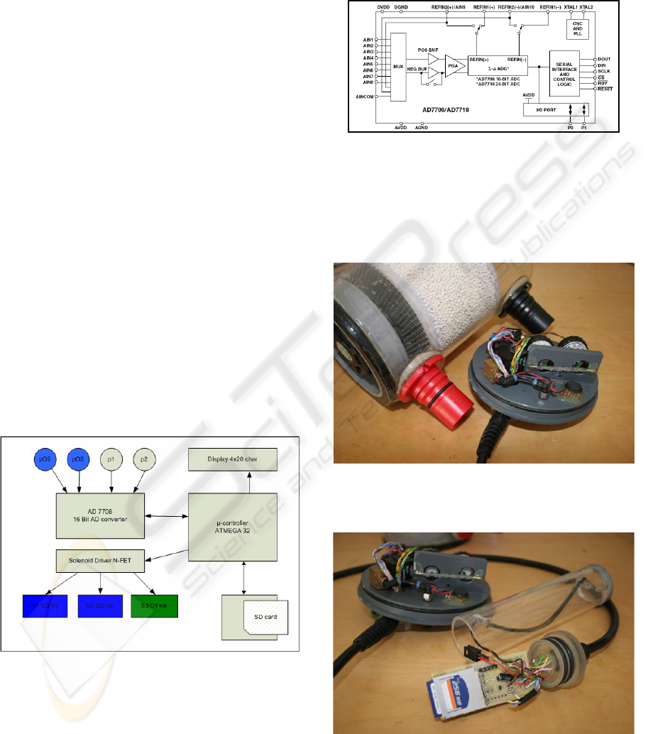
2.3 Electronics - Hardware
As core component of the electronics the 8 Bit RISC
microcontroller ATMEGA 32 from ATMEL () was
chosen (32kByte flash ROM, 2 kByte RAM). A
4x20 characters display is connected via SPI bus
(EA DIP 204-4, www.lcd-module.de). To enable a
detailed post dive analysis a slot for SD memory
cards was integrated in the set up. Three N-FET
NDS355 serve as solenoid drivers.
Figure 4: Electronics.
For the sensor signal processing the 16 Bit
AD7708 (figure 5) analog to digital converter from
Analog Devices is connected via SPI bus to the
microcontroller. Its high resolution and the
programmable input stage allows directly connecting
the pO2 sensors (electrochemical pO2 sensors used
in rebreathers have a typical output signal of
approximately 8-13 mV @ 0,21 bar pO2). Two
Motorola MPX5999 pressure sensors are used to
measure on the one hand the ambient pressure (there
the negative pressure port is closed) and on the other
hand the differential pressure of the reservoir to
ambient.
Figure 5: Analog Devices AD 7708.
Two low drop voltage regulators from Texas
Instruments are used to provide 5V for the
microprocessor, the display, the AD converter and
the pressure sensors and 3,3V for the operation of
the SD memory card.
Figure 6: Scrubber and scrubber head with solenoids,
pressure sensors and two pO2 sensors (Analytical
Industries, PSR 11-39-MD2).
Figure 7: Electronics with the SD card slot and the lexan
housing depth rated to 120 m.
NOVEL CONTROLLER FOR REBREATHER DIVING SYSTEMS - True Sensor Signal Validation and Safe Oxygen
Injection
47
2.4 Software
As programming platform the ATMEL AVR Studio
4 together with the free of charge GNU C compiler
WinAVR (http://winavr.sourceforge.net/) was used
under Windows XP.
The pO
2
control loop is designed in a way to
keep the pO
2
inside the loop constant at 1,3 bar at a
depth greater than 16 m. In the range between the
surface and 16 m the pO
2
is increasing linear from
0,5 bar on the surface to 1,3 bar in 16m (compare
figure 9 A and 9 B).
Error messages are created if a pO
2
sensor signal
is outside the limits, the sensor signals differs more
than 0,01 bar from each other, the battery voltage is
below 6,5V and if the calculated O
2
metabolism of
the diver is less than 0,3 or more than 3 bar l / min.
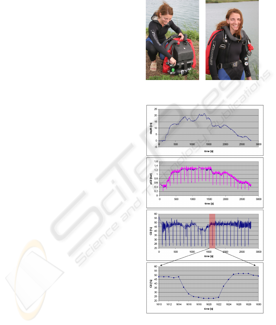
Every 120 seconds the sensor signal validation
procedure with diluent as validation gas is carried
out which results in the spikes in the readings of the
pO
2
sensors (figure 9B, 10C). During the validation
cycle the calculated O
2
in % has to drop to a value
less than 25% (figure 9C and 9D). If not, an alarm
signal is generated.
Optionally at a depth between 6 and 10 m once a
dive the pO
2
sensors are checked for linearity and
current limitation by injection of pure O
2
in front of
the sensor membrane.
For the pre dive preparations the system can
perform automatically a negative pressure test, a
positive pressure test and the pO
2
sensor calibration.
All sensor data are stored on SD card in
spreadsheet format. FAT 16 or FAT 32 formatted
SD memory cards can be used. For each dive a new
file is created. Additionally data like battery voltage,
oxygen injection, oxygen consumption and error
messages are stored.
3 RESULTS
This novel device with its true sensor signal
validation and the safe oxygen injection is the key
component of our eCCR prototype with the
following specifications:
• Outer dimension: 45x25x18 cm³
• Scrubber: 1,5 kg
• Max depth: 50m
• 1 oxygen tank: 1,5 l, 200 bar
• 1 diluent tank: 1,5 l, 200 bar
• total weight: 12 kg
• maximum dive time: 180 min
After the dive the SD card can be read out with
every PC equipped with a memory card reader and
visualized with suitable programs like Microsoft
EXCEL Figure 9 shows data of a test dive with 45
min duration to a maximum depth of 22m.
(a) (b)
Figure 8: One of our eCCR test divers is preparing for a
dive with our first prototype.
Figure 9: Data of a 45 min test dive in the mediterranian
sea to a maximum depth of 22m; A: depth profile; B: pO
2
sensor signals of 2 sensors; C: calculated %O
2
; D: one
validation cycle.
BIODEVICES 2008 - International Conference on Biomedical Electronics and Devices
48

4 CONCLUSIONS
ECCR have a variety of advantages like:
- silent diving
- no bubbles
- maximized gas efficiency
- warm breathing gas
- humid breathing gas
Disadvantages are that the control of the pO
2
to
keep it within life sustaining limits at a constant
level depends on sensors which, with a low mean
time between failure (MTBF) of less than a year, are
prone to fail. State of the art solution is to deploy 3
pO
2
sensors for redundancy. This allows a reliable
detection of one sensor failure, but cases, where
more than one sensor show the same wrong values
cannot be detected, which may lead to a non life
sustaining pO
2
inside the loop followed by the death
of the diver. A stuck open solenoid is another failure
that may occur in a eCCR, resulting in a free flow of
O
2
, where the pO
2
inside the loop is increasing
rapidly, or the case where the solenoid is stuck
closed allowing no injection of fresh O
2
inside the
loop anymore.
The present paper describes a novel apparatus
that combines true sensor signal validation and a
reliable sensor failure detection with a safe injection
of O
2
, where cases like a free flow of O
2
are not
possible anymore.
In principle the apparatus can work with just one
pO
2
sensor, where in the case of a sensor failure a
alarm is given telling the diver to use his separate
emergency gas supply in open circuit mode and to
abort the dive.
As this system needs just one (or for redundancy
two pO
2
sensors, in the case of the failure of one pO
2
sensor, the dive can be continued with the other
working one). The costs for the yearly maintenance
are dramatically decreased (pO
2
sensors should be
changed once a year).
The authors are convinced that the further
development of this novel device will lead to a novel
kind of diving device for recreational purposes with
a dramatically increased safety, low weight of the
overall system and independency (180 min
maximum dive duration).
5 FUTURE WORK
Near future work will include a further development
of the presented electronics, an integration of a
second controller for redundancy, a head up display
mounted on the mouthpiece with LEDs for status
information and a breathing frequency sensor. As
the breathing frequency increases with increasing
work load (and O
2
metabolism), this parameter
allows another cross check giving more safety to the
final product.
Typical for electrochemical pO
2
sensors for
diving is that at the end of the dive the signal is
slightly deviating from the reference signal (during a
dive the sensors are very warm and humid gas under
high pO
2
, factors which present a quite extreme
environment – so even if most pO
2
Sensors are
temperature compensated changes in the slope of the
sensors are not unusual during a dive) Another
function that will be implemented in the next
firmware release is an advanced sensor signal
processing that, in the case of relatively small signal
deviations allows a sensor recalibration during the
dive (but only if the sensor is still linear, which can
be checked with 2 reference gases (O
2
and diluent).
REFERENCES
Divers Alert Network, 1992, Report on Diving Accidents
& Fatalities, Divers Alert Network, Box 3823, Duke
University Medical Center, Durham, NC 27710, 1994.
U.S. Navy Diving Manual, 2005, Volume 2 and Volume
4, SS521-AG-PRO-010, Direction of Commander,
Naval Sea Systems Command, USA
NOAA Diving Manual, Diving for Science and
Technology, 4
th
edition, US Department of Commerce,
National Technical Information Service, Springfield
Ehm, O.F., Hahn, M., Hoffmann, U., Wenzel, J., 1996,
Der neue Ehm, Tauchen noch sicherer, 9th edition,
ISBN 3-275-01484-6, Mueller Rueschlikon Verlags
AG, CH-6330 Cham.
Dederichs, H., Floren, G., Waldbrenner, M., Wilhelm, R.,
2004, Handbuch Technisches Tauchen, ISBN 3-275-
01492-7, Mueller Rueschlikon Verlags AG, CH-6330
Cham.
Mount, T., Gilliam, B., Bohrer R., Taylor, L., Sommers, L.
H., Crea, J., Nordsteam, R., 1992, Mixed Gas Diving,
ISBN 0-922769-30-3, Watersports Publishing, San
Diego, USA.
Deas, R.A., Evtukhov, M.V., 2003, Control electronics
system for rebreather, UK Patent Application, GB
2404539 A.
Deas, R.A., Evtukhov, M.V., 2003, Automatic Control
System for Rebreather, United States Patent
Application Publication, US 2003/0188744 A1
Baran, U., Frost, A.J., 2004, Diving Equipment Monitor,
PCT, WO 2004/112905 A1
Straw, P.E., 2005, Rebreather Setpoint Controller and
Display, PCT, WO 2005/107390 A2
Parker, M., 2005, Evolution Closed Circuit Rebreather
and Inspiration Closed Circuit Rebreather, Ambient
Pressure Diving Ltd., Helston, Cornwall, UK
NOVEL CONTROLLER FOR REBREATHER DIVING SYSTEMS - True Sensor Signal Validation and Safe Oxygen
Injection
49
