
MECHATRONIC SYSTEM FOR TRANSURETHRAL
RESECTION TRAINING
Ángel Asensio, Alejandro Ibarz, Jose Ignacio Artigas, Álvaro Marco
Javier Casas and Roberto Casas
Instituto de Investigación en Ingeniería de Aragón, Universidad de Zaragoza, María de Luna 1, Zaragoza, España
Keywords: Transurethral resection, TUR, endoscopic operation.
Abstract: Training the residents who start with endoscopic operations remains a challenge. This paper describes an
electromechanical system developed for learning the transurethral resection (TUR) technique. This system
can be easily set and cleared up in a classroom, and consists of a supervisor’s workbench with a wireless
sensing device, connected to several trainees’ workbenches with motorised devices. These devices have a
resectoscope mounted on an electromechanical structure that is able to reproduce all the movements of an
actual endoscopic operation of the prostate.
1 INTRODUCTION
Transurethral resection (TUR) is an endoscopic
surgical technique that makes it possible to extract
tissue from the prostate in mitigating or corrective
operations. It is performed by means of a
resectoscope, consisting of a thin cannula that
includes an endoscopic lens system and contains a
tiny wire loop acting as an electro-scalpel, and
operated from the exterior.
Nowadays, video-surgery has simplified TUR
training, becoming a common practice among many
urologists. However, no urologist hesitates to
consider learning this technique difficult and time-
consuming. Mere vision of the moving endoscopic
image is not enough to acquire the reflexes, manual
skill, and mental agility necessary to cope with the
recurring occasions in which only solid practical
experience will make it possible to handle the
situation, and conclude the operation successfully
(Pycha, 2003).
Traditional training for novel surgeons is carried
out by first explaining the techniques with
endoscopic images, to later begin performing very
simple operations, directly in the operating theatre.
Work has been done on support for training in
endoscopic techniques, and there have also been
efforts to devise manipulators for motorised
operations guided by the surgeon (Kerfoot, 2004;
Gettman, 2003; Katz, 2003; Ottensmeyer, 2000;
Ballaro, 1999; Gomes, 1999). However, these
systems have certain problems, such as lack of
tactile feedback, and their high cost for generalised
use in training. Their main objective is to automate
operations, not to perform exact imitations of the
movements of a surgeon. Our system achieves a
great precise reproduction of the movements of an
expert surgeon, at a much lower cost.
Another difference with the mentioned line of
work is that our proposal aims at low-cost robot
systems, specific for this operation, capable of
capturing the movements of the resectoscope and
reproducing them both in real time and recorded.
For this, we have devised an easy to set and clear
up lecture room, practical for use at hospitals. The
room has a sensing workbench connected to a
computer, and several motor workbenches linked by
Bluetooth. All these workbenches are able of
reproducing the movements of a hand at the degrees
of freedom of the resectoscope. A video monitor
shows images of an operation. The sensing
workbench senses the movements performed upon
it, and the motor workbenches are able of
reproducing these movements.
The solution we present in this paper is cost-
effective, and has been successfully tested by
experienced surgeons. First we detail the specific
goals pointed out by the users, which guided us in
the design of the solution presented; Next, we
analyze in depth each block of the final system.
74
Asensio Á., Ibarz A., Ignacio Artigas J., Marco Á., Casas J. and Casas R. (2008).
MECHATRONIC SYSTEM FOR TRANSURETHRAL RESECTION TRAINING.
In Proceedings of the First International Conference on Biomedical Electronics and Devices, pages 74-81
DOI: 10.5220/0001051300740081
Copyright
c
SciTePress

2 SYSTEM GOALS
The aim of our system is to aid learning of a
complex technique of endoscopic surgery,
transurethral resection, in order to improve the skill
of surgeons and reduce risks for patients. We try to
offer a lecture room that permits training in
techniques as they are currently performed, in such a
way that its structure allows inclusion of more data,
and with feasible installation in hospitals (easily set
and cleared up in multipurpose halls).
Thanks to the system’s modular structure,
several different teaching modes are possible:
1. Real time teaching mode: The trainer operates
the sensing workbench and movements are repeated
in the hands of trainees by means of the motor
workbenches. The trainer’s explanations can be
underlined by videos played on the computer.
2. Recording mode: The trainer watches an
endoscopic video on the computer, and
simultaneously performs the corresponding
movements with the sensing workbench. The
movement pattern is stored in the computer, and a
video of the operation with embedded information
on positions is generated. This video will be used
later to control motor workbenches without the
presence of the trainer.
3. Recorded teaching mode (without the
presence of the trainer): The computer plays a pre-
recorded video that controls the motor workbenches.
4. Trainee assessment without trainer: A video is
played and trainee operates the sensing workbench;
movements are stored in the control board of the
sensing workbench. Once the test has ended, data
are sent to the trainer’s computer, and they are
checked against the movement pattern of the expert
surgeon.
The technical requirements we have had to deal
with are the following:
– The workbenches must reproduce movements
with the same degrees of freedom that the surgeon
has during an actual operation. The initial hypothesis
is that the urinary tract sphincter is fixed in space,
which leads us five degrees of freedom. The
correctness of this hypothesis and the validation of
the movement replicator have been checked during
the research actions performed by the group.
– Another very important requirement is
synchronization of the endoscopic video playing
with the movements of the resectoscope.
– To ensure portability, we envisage a
radiofrequency workbench data communications
structure using Bluetooth (Anastasi, 2003).
Bluetooth chips available on the market managed
from a microcontroller based system have been
used. Both the hardware and the firmware have been
original developments aimed at the present final
application.
– One last goal is to allow collection of actual
movements data in the operating theatre. In this
scenario it is not possible to modify the instruments
available to the surgeon, nor interfere with his
movements. To achieve this, we propose a new
method for sensing and capture of the movement of
the resectoscope in the operating theatre, based on
ultrasound.
3 DESCRIPTION OF THE
ENVIRONMENT
3.1 Basic Scenarios
Next we briefly describe the structure of a possible
lecture room. It should be pointed out that some
systems share certain common blocks, so these will
be described only once.
3.1.1 Trainer’s Workbench
Its role is that of a general coordinator, and it
comprises several clearly distinct subsystems
(Figure 1).
The resectoscope or instrument to be used by the
medical personnel is mounted on a mechanical
system that allows mobility as if an operation were
being performed. For this, three turns (coordinate
axes) and two sweeps (cannula and resection loop)
are allowed. The trainer will introduce the sequence
of movements using this workbench. A set of
position encoders capture kinetics directly, or by
means of the corresponding transmission ratios.
A digital system based on a Field Programmable
Gate Array (FPGA) has been developed for data
collection tasks, management of communications,
motor device control and memory management.
Previous developments were based on
microcontroller solutions, but the large number of
inputs-outputs and the need for concurrence
recommended migration to programmable logic
devices. The use of FPGA allows for modular and
flexible design, which eases the integration of the
various subsystems developed.
A Bluetooth device in this workbench acts as a
master of the wireless communications system. It is
possible to control a complete network, commanding
the various devices and modes, and at the same time
the various flows of information.
MECHATRONIC SYSTEM FOR TRANSURETHRAL RESECTION TRAINING
75
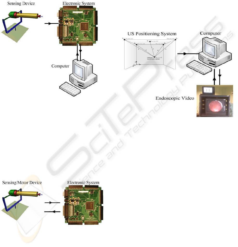
Acting as a central server, the trainer’s
workbench relies on computer equipment offering
various functions: It controls reproduction of the
TUR operation video; it allows storage of movement
patterns for later analysis or repetition; and it
manages communications and state of the devices in
the lecture room by means of Bluetooth linking via
electronic system.
Figure 1: Trainer’s workbench.
3.1.2 Trainee’s Workbench
The mechanical structure is similar to that of the
trainer’s workbench (Figure 2). It includes the
electromechanical devices allowing reproduction of
movements. The student holds the device and feels
the movement to be performed. The device retains
the position encoders, making available a process of
auto-calibration without the need of supervision by
the user. A Bluetooth device acts as a slave in the
network managed by the trainer’s workbench.
Figure 2: Trainee’s workbench.
3.1.3 Installation in Operating Theatre
Figure 3 shows the block diagram of the installation
in operating theatre. Encoder-based position capture
is not possible in the operating theatre, since the set
of instruments cannot be modified (figure 4). We
have therefore developed a novel positioning
technique based on ultrasound (US) pulses, with the
aim of applying it to the capture of the movements
performed by the surgeon on the resectoscope in the
operating theatre. In this way, it will be possible to
document fragments of actual operations with the
video information, movements, and other parameters
that may be considered relevant. We should point
out that the training video is obtained by an
endoscopic camera during the operation. Later on,
and as a previous step to its use in the training
system, it is processed by the computer system.
Figure 3: Installation in operating theatre.
3.2 Mechatronic System
Initially, the typical movement of the resectoscope
in an operation was studied. Considering the results,
to express the movement as parameters, the
following hypothesis is adopted: “The point of the
resectoscope oppressed by the sphincter is
considered still, and this point does not vary
throughout the operation”.
To all practical effects, it is considered as the
origin of the coordinates of the mechanical system.
On the basis of this hypothesis, the conclusion
reached is the need to design a mechanical system
allowing three angular movements, one forward
movement for the cannula, another for the cutting-
loop, and two for the switches of irrigation and
coagulation. To sum up, seven coordinates are used
to define the state of the device at a given moment.
Four of them reflect the point in space where the end
of the resectoscope is, another the state of the cutting
loop, and the remainder refer to the state of the
switches the resectoscope is equipped with
(generally pedal-operated).
BIODEVICES 2008 - International Conference on Biomedical Electronics and Devices
76
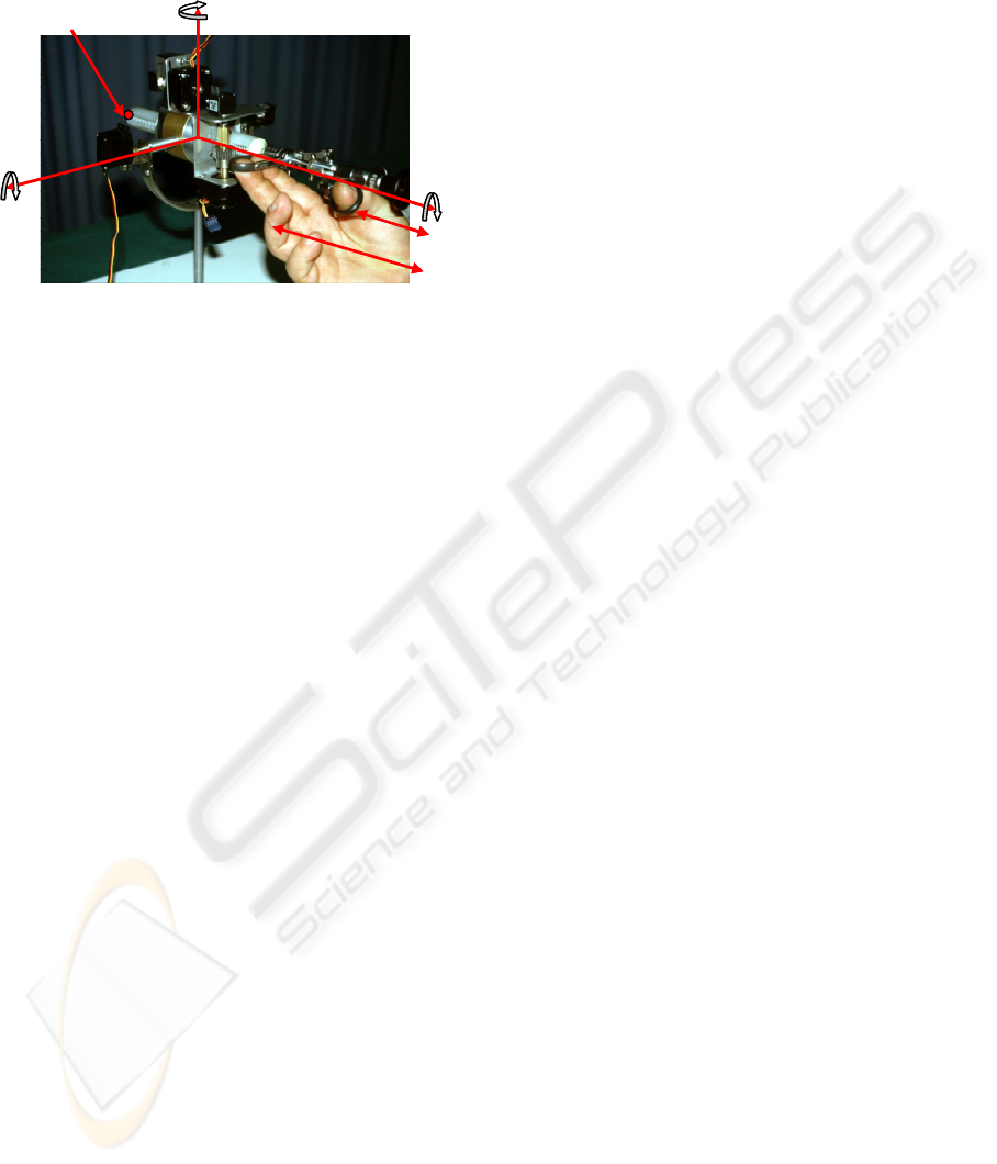
According to the explanation offered, the
mechanical system should allow the movements
detailed in Figure 4.
Turn 3
Turn 2
Turn 1
H
a
n
d
le
F
o
r
w
a
r
d
Extreme of
resectoscope
Turn 3
Turn 2
Turn 1
H
a
n
d
le
F
o
r
w
a
r
d
Extreme of
resectoscope
Figure 4: Kinetic diagram of the resectoscope.
The final system has been the result of several
different prototypes. At the moment of designing the
mechanical system, we have two different kinds of
devices:
Sensing device: Conveniently equipped with
encoders in order to capture the movements
performed with it.
Motor device: Fitted with servo-motors to
reproduce movement. In the design phase, this
device is also equipped with sensing elements in
order to carry out calibration and performance
measurements.
The present design is capable of completely valid
mobility. The sensing workbench can most
realistically imitate any type of operation. Both the
sensing and motor workbenches share a similar
design, so that they may or may not include motors
and sensors, that they may have the required
functionality on the basis of a single development.
The mechanical similarity between them likewise
eases the generation of movements from the stored
kinematics.
Various alternatives have been checked for
movement generation, among which we could
feature step-motors and servo-motors. The latter
presents suitable speed-torque characteristic curves,
which together with their simple handling have
made them the chosen solution. Different kinds of
movement must be generated, angular for the three
coordinate turns, and longitudinal for the cannula
and resection movements. In order to achieve linear
movements, mechanical transmission chains have
been designed, based on the turning of the servo-
motor.
The measurement of the three angular
movements is performed with angular encoders. The
linear movements are indirectly measured from the
electromechanical rotation system. In this way we
can use the same kind of sensor for the different
movements, with all the advantages of uniformity
and simplicity. Specifically, the encoder chosen will
be of the digital type and incremental.
Once the mechatronic system implemented, the
performance, both kinetic (speed, accelerations,
movement ranges and sensitivity) and dynamic
(torque) of the system was tested. For this,
automated tests have been devised to check the step
and ramp response of each motor device.
Finally, several tests were carried out by the
medical team, with the goal of simulating the
different kinds of movements that actual operations
might require. Two models were simulated:
cystoscopy (inspection) and resection (operation), as
well as a mixed model including various types of
movement. On the basis of these tests, we can state
that our system correctly replicates a model
operation.
3.3 Synchronization
In the system, various temporal distortions may
appear, which can generically be grouped as two
different sets of problems:
– Data delay: An ideal design in the FPGA will
make this negligible in the context of the time
intervals operated with.
– Loss of synchronization and regularity between
video frames and mechanical positions: Critical
aspect. The computers might be unable to send the
movement data in a totally regular and predictable
way while it reproduces a video or is handling other
processes.
Different alternatives have been checked:
synchronization by means of video subtitles, real-
time operative systems, and modulation in audio
channel.
The solution finally adopted is based on use of
the video’s audio channel. To include the digital
information of positions on an analog audio signal,
Manchester encoding has been chosen. It has been
decided to encode and send the sampling number
corresponding to each video frame, rather than all
the data for each frame. A Hamming code with
distance 4 is applied, to minimize environmental
noise. This strategy will make it possible to detect
up to three bit errors, and correct up to one bit. The
frame under the Hamming format is Manchester
encoded and modulated upon the audio channel.
Both processes have been carried out with Matlab.
The final application generates an audio file
containing the sampling numbers, spaced the exact
MECHATRONIC SYSTEM FOR TRANSURETHRAL RESECTION TRAINING
77
time needed. This file is included in the video, so
that we have a video with exact time marks
indicating a sampling number. In normal use, an
audio channel carries the frame number we are at,
and the other channel may include trainer’s
comments.
Before the use of a trainee’s workbench, a
massive download of positions in each motor system
is performed from the computer to the local FPGA.
During the video playing, the time marks are
extracted and the local memory is searched for the
associated positions.
3.4 Computer System
The computer system presents two layers. One of
them is opaque to a certain degree for the end user,
and collects the data of the different blocks and
integrates them. Also, it calculates the kinematics of
the resectoscope during the operation, using the
obtained data from the ultrasound location system.
Finally, it generates the movement references for the
device, synchronized with the endoscopic video.
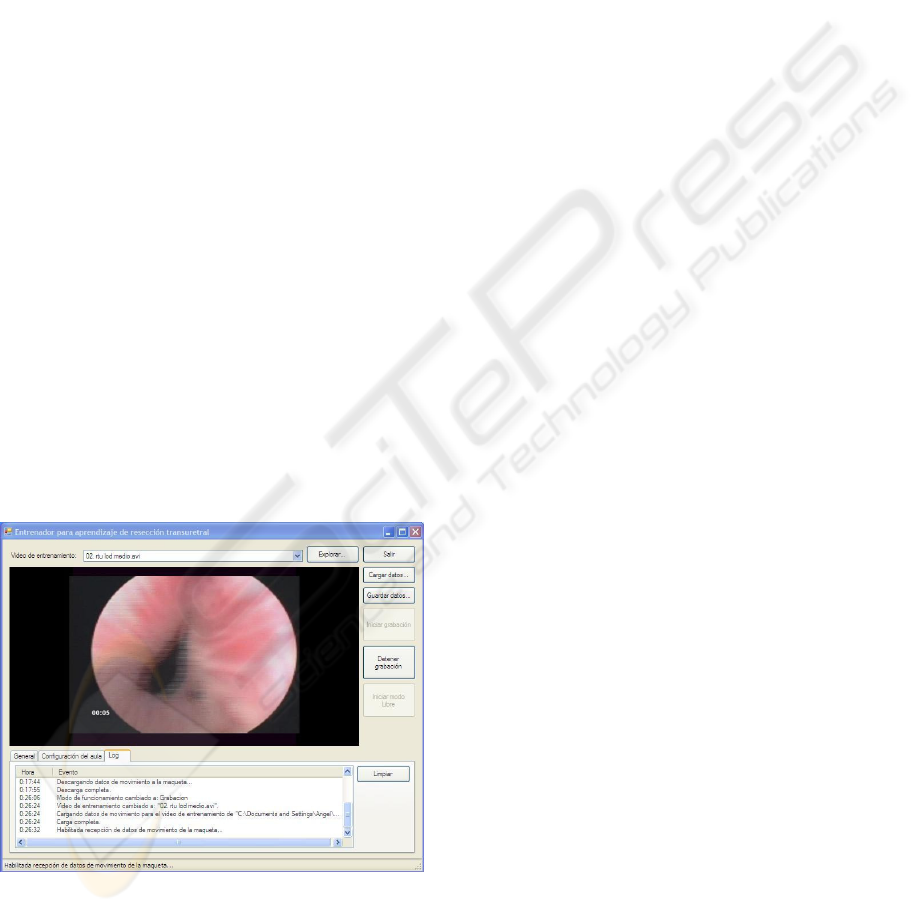
The computer system has another aspect,
intended for the end user in the training context. A
simple and friendly user interface is offered for
interaction in the lecture room (Figure 5). It includes
a video player and a manager of the various
operation modes that the trainer may request. The
more tedious tasks, such as Bluetooth node
management and processes with data files have been
completely automated.
Figure 5: Computer system. User interface.
4 OPERATING THEATRE
POSITIONING
It is interesting to see how different data are
obtained in the operating theatre, such as the
endoscopic video of the operation and the actual in
situ trajectory followed by the resectoscope.
Obtaining the endoscopic video is possible with
commercial equipment, so we will concentrate on
the analysis of the problems regarding highly
accurate location. The different alternatives allowing
a sufficiently exact positioning were analyzed, with
the main focus on optical, radiofrequency and
ultrasound solutions. Several aspects, such as
economy and environmental constraints pointed to
ultrasound positioning as the ideal method.
Through high precision positioning by
ultrasound waves, it is possible to locate an object
within a given volume with a tiny error margin,
simply and quickly, without any necessary physical
contact with the point to be referenced (Fukuju,
2003; Casas, 2004; Mahajan, 2001; Prigge, 2000).
The initial idea was to obtain a system allowing
capture of the position of the resectoscope during an
actual operation in the operating theatre; the system
should therefore have very restrictive features.
In the case of our application, there are certain
key aspects defining the location system, due to the
characteristics of work in an operating theatre.
The range of the system must agree with the
dimensions of the operating theatre (in our case, up
to 3.5 metres).
Given the need for a precise reading of the
kinematics and of the position of the resectoscope,
the positioning refresh rate must be as high as
possible. It has been possible to obtain up to twenty
references per second.
In order to achieve millimetric errors in the
position of the resectoscope, it was necessary to
analyze other factors of the design: the possibility of
background noise, disadjustment of probes,
environmental factors (temperature and humidity),
and reflected ultrasound waves due to reflecting
surfaces.
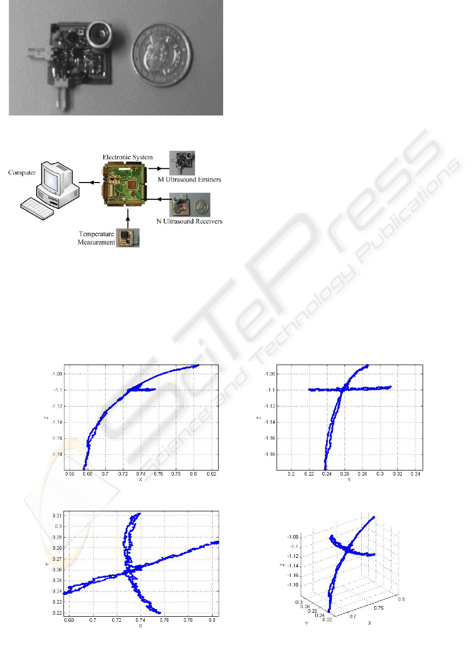
The probes of the emitter modules (Figure 6) are
joined to the resectoscope in fixed positions. Three
probes are usually necessary in order to later infer
the position and direction of the instrument from
them.
The receiving probes will be attached to the
ceiling of the operating theatre in positions with
known coordinates, with the necessary precision to
later give references for the emitting probes in the
BIODEVICES 2008 - International Conference on Biomedical Electronics and Devices
78
space. A redundant number of probes make possible
to minimize the effects of occlusions.
The system includes the blocks shown in figure
7.
The control system will send a signal to the
corresponding emitter modules, to generate the
ultrasound pulse train, and simultaneously the time-
of-flight of the ultrasound waves to the receiver
modules will be measured. During the time-of-flight
of the ultrasound pulses a measurement of the
temperature will be obtained, to compensate the
data. The features and pattern of the pulse trains
generated are critical for the system. Their
generation is based on a self-interference strategy, in
which the optimum phase and counter-phase periods
have been obtained analytically and empirically. In
the receiver, filtering is an equally delicate process,
articulated around a second order Rauch filter
followed by a high speed comparator.
The receiver modules will send the received
signal, filtered and conditioned, to the FPGA, which
will capture and process the data in order to
calculate the times-of-flight of each emitter-receiver
pair, as well as reliability indicators of each
measurement for their later processing. Once all of
the data have been processed, it will send all the
information obtained to the computer together with
the temperature measurement. The computer will
calculate the distances between each of the emitter-
receiver pair.
After obtaining the distances between emitter and
receiver probes, the coordinates of the emitter
probes are calculated by an algebra resolution
Figure 6: Emitter probe.
Figure 7: Precision positioning block diagram.
Figure 8: Positions of the end of the resectoscope.
Front Left
To
p
3D
MECHATRONIC SYSTEM FOR TRANSURETHRAL RESECTION TRAINING
79

method (Casas, 2004) and a solution filtering
algorithm based on the least median of squares
(Casas, 2006). Once the positions of the emitter
probes have been obtained, the trajectory of the
resectoscope is obtained as well.
In order to verify the system, an experiment set-
up has been designed with the motor workbench
managed by the computer system in auto-calibration
mode. Figure 8 illustrates the results obtained. It
shows the position of an emitter probe located at the
end of the resectoscope. An emitter transducer is
attached to the mock up, which moves using a
predefined pattern. With three receivers, the results
are very accurate (few millimetres), and even the
bounces and oscillations of the mechanical system
itself can be detected.
5 CONCLUSIONS
Training surgery residents who start with endoscopic
operations remain a challenge. This paper has
described an electromechanical system developed
for learning the TUR technique. It consists of a
trainer’s workbench with a wireless sensing device
connected to several trainees’ workbenches with
motorised devices. These devices have a
resectoscope mounted on an electromechanical
structure able to reproduce all the movements of an
actual endoscopic operation.
The system has several operating modes that will
make it possible to:
– Reproduce the movements of an expert
surgeon in the hand of the trainee.
– Reproduce the pre-recorded movements of an
actual operation in the hand of the trainee.
– Assess the level reached by the student before
participation in any operations or in solving
problems requiring a certain degree of experience.
As a complement, a millimetrically accurate,
ultrasound-based positioning system has been
developed. This will be mounted on a resectoscope
in order to capture the movements performed in an
real operation. The management software of the
training room allows easy integration of these data
with the endoscopic video, to rely on an adequate
operations database.
What remains is to assess this tool in the
practical conditions of training urology residents in
the use of medical equipment, which will doubtless
offer most interesting data regarding the use or need
for modifications of the global system.
ACKNOWLEDGEMENTS
This work has been partially supported by the
Spanish Ministry of Science and Technology under
CICYT project numbers TIC2003-07766 and
TIN2006-15617-C03-02
REFERENCES
Anastasi, G., Bandelloni, R., Conti, M., Delmastro, F.,
Gregori, E. Mainetto, G., 2003. Experimenting an
Indoor Bluetooth-based Positioning Service.
ICDCSW’03, Proc. of the 23rd Int. Conf. on
Distributed Computing Systems Workshops, 480-483.
Ballaro, A., Briggs, T., Garcia-Montes, F., MacDonald,
D., Emberton, M., Mundy, A.R., 1999. A computer
generated interactive transurethral prostatic resection
simulator. The Journal of Urology, 162 (5), 1633-
1635.
Casas, R., 2004. BLUPS: Bluetooth and Ultrasounds
Positioning System. Doctoral Dissertation, University
of Zaragoza.
Casas, R., Marco, A., Guerrero, J.J., Falcó, J., 2006.
Robust Estimator for Non-Line-of-Sight Error
Mitigation in Indoor Localization. EURASIP J.
Applied Signal Processing, vol. 2006, article ID
43429, 1–8.
Fukuju, Y., Minami, M., Morikawa, H., Aoyama, T.,
2003. DOLPHIN: An Autonomous Indoor Positioning
System in Ubiquitous Computing Environment. Proc.
of the IEEE Workshop on Software Technologies for
Future Embedded Systems, 53-56.
Gettman, M.T., Hoznek, A, Salomon, L, Katz, R,
Borkowski, T, Antiphon, P, Lobontiu, A, Abbou, C.C.,
2003. Laparoscopic radical prostatectomy: Description
of the extraperitoneal approach using the Da Vinci
robotic system. The Journal of Urology, 170 (2 Pt 1),
416-419.
Gomes, M.P.S.F., Barret, A.R.W., Timoney, A.G., Davies,
B.L., 1999. A computer-assisted training/monitoring
system for TURP structure and design. IEEE Trans.
Information Technology in Biomedicine, 3 (4), 242-
251.
Katz, R, Nadu, A, Olsson, L.E., Hoznek, A, De La Taille,
A, Salomon, L, Abbou, C.E., 2003. A simplified 5-
step model for training laparoscopic urethrovesical
anastomosis. The Journal of Urology, 169 (6), 2041-
2044.
Kerfoot, B.P., Baker, H, Volkan, K, Church, P.A.,
Federman, D.D., Masser, B.A., De Wolf, W.E., 2004.
Development of validated instrument to measure
medical student learning in clinical urology: A step
toward evidence based education. The Journal of
Urology, 172 (1), 282-285.
Mahajan, A., Walworth, M., 2001. 3-D Position Sensing
Using the Differences in the Time-of-Flights from a
BIODEVICES 2008 - International Conference on Biomedical Electronics and Devices
80

Wave Source to Various Receivers. IEEE Trans.
Robotics and Automation, 17 (1), 91-94.
Ottensmeyer, M., Ben-Ur, E., Salisbury, K., 2000. Input
and Output for Surgical Simulation: Devices to
Measure Tissue Properties in vivo and a Haptic
Interface for Laparoscopic Simulators. MMVR'2000,
Proc. of Medicine Meets Virtual Reality, IOS Press,
236-242.
Prigge, E., How, J., 2000. An Indoor Absolute Positioning
System with No Line of Sight Restrictions a Building-
Wide Coverage. ICRA'00, Proc. IEEE Int. Conf. on
Robotics and Automation, 2, 1015-1022.
Pycha, A., Lodde, M., Lusuardi, L., Palermo, S.,
Signorello, D., Galantini, A., Mian, C., Hohenfellner,
R., 2003. Teaching transurethral resection of the
bladder: Still a challenge?. Urology, 62 (1), 46-48.
MECHATRONIC SYSTEM FOR TRANSURETHRAL RESECTION TRAINING
81
