
COMPUTER-CONTROLLED NEUROSTIMULATION
FOR A VISUAL IMPLANT
S. Romero
Department of Computer Science, University of Jaén, Campus Las Lagunillas s/n, Jaén, Spain
C. Morillas, F. Pelayo
Department of Computer Architecture and Technology, University of Granada, Granada, Spain
E. Fernández
Institute of Bioengineering, University Miguel Hernandez, Elx, Spain
Keywords: Artificial vision, electrical neurostimulation, microelectrodes, active implants, phosphene, neuroprosthesis.
Abstract: Current research in therapies for restoring a functional form of sight to the blind includes interfacing
electronic neurostimulators with some point of the visual pathway. This approach requires controlling a
number of waveform parameters which might vary for every implanted patient and for every channel in an
interface that may have hundred or thousands of electrodes. Therefore, the clinical, acute research stage of
the implant should be controlled in a flexible and easy way, in order to obtain the information that will lead
to a chronic implantable device. We describe such a system, based on a PC connected to an electronic
neurostimulator, which delivers bi-phasic pulses to a set of implanted microelectrodes. This platform
performs an automated patient-driven procedure to find stimulation thresholds. The system implements a set
of physchophysical tests in order to determine the properties of the elicited visual perceptions, and applies
an automatic re-mapping of the electrodes to obtain better recognizable patterns of percepts. Our platform
can interface some other tools oriented to obtain, in a next research stage, a portable and chronic version of
the visual implant.
1 INTRODUCTION
World Health Organization estimates that about 37
million persons are completely blind, while those
affected by low vision sum up to 124 million (WHO,
2005). These numbers are increasing due to the
ageing of population in developed countries, and to a
variety of pathologies and accidents affecting one or
more of the components of the complex visual
system.
Major causes of blindness are age-related
macular degeneration (AMD), diabetic retinopathy,
glaucoma or traumatic damage.
Therapeutic choices for blindness might be as
varied as its causes. Clinical treatments are available
for some kinds of visual impairments, as the ones
caused by cataracts. However, a strong research is
undergoing for other types of visual pathologies, for
which no clinical solutions are available yet.
These research lines include retinal cell
transplantation, the use of growth factors, or gene
therapy, mainly applied to retinitis pigmentosa (RP).
Apart from biological approaches, a number of
research groups are working towards the
development of visual prostheses, which would
replace one or more of the damaged stages of the
visual pathway, providing a rudimentary, but
functional, form of visual perceptions.
Depending on the point of the visual pathway on
which the neurostimulation interface is placed, we
can classify visual neuroprostheses as retinal
(Humayun, 2003), optic nerve (Veraart, 1998), or
cortical implants (Dobelle, 2000; Troyk, 2003;
Fernández, 2005).
84
Romero S., Morillas C., Pelayo F. and Fernández E. (2008).
COMPUTER-CONTROLLED NEUROSTIMULATION FOR A VISUAL IMPLANT.
In Proceedings of the First International Conference on Biomedical Electronics and Devices, pages 84-91
DOI: 10.5220/0001051600840091
Copyright
c
SciTePress
In retinal prostheses, the set of electrodes are
implanted below or onto the retina, in order to
replace the role of photoreceptors, or ganglion cells,
respectively. In the case of optic nerve implants, a
cuff electrode is placed around the bunch of axons of
the ganglion cells connecting the output of the retina
to the next stage of the visual pathway. In cortical
implants, electrical pulses are directly delivered to
the visual area of the brain cortex, by using surface
planar electrodes, or penetrating tips.
Whatever is the selected interface for visual
neurostimulation, the employment of this kind of
devices implies a high degree of complexity.
The amount of channels in the different
prototypes used in research range from 16 to 100
electrodes (Normann, 1999), although some studies
have shown that a number between 600 and 1000
electrodes would be required to obtain an adequate
performance in basic tasks, such as object
discrimination, recognition of big characters or
pedestrian navigation (Cha, 1992).
The signal delivered to every electrode is a bi-
phasic charge-balanced pulse, and includes a set of
parameters such as phase width, pulse duration,
pulse current amplitude, number of pulses in a train,
inter-pulse interval, inter-train interval, etc. The set
of values for these parameters might vary from
channel to channel, and are expected to be different
for every implanted individual (see Fig. 1).
This way, the process of tuning all the
parameters for the prosthesis after safe implantation
is a complex and lengthy task, which is unavoidable
in the research to determine the feasibility of a
neurostimulation-based visual prosthesis.
In this paper, we describe a computer-based set
of software and hardware conceived for research
with visual neuroprostheses. Our platform is mainly
oriented to test cortical implants, but it is easily
extendable for other types of implants.
The purpose of the research platform is to
provide automated and patient-driven procedures for
prosthesis parameter tuning and psychophysical
testing. The computer-controlled neurostimulator
serves as an abstraction layer to hide the complexity
of handling such an intricate implant.
The platform is part of a set of tools designed to
cover different needs in the development of a full
visual prosthesis, such an artificial retina model, or
an automated synthesizer for embedded circuits to
obtain a portable, low power consumption controller
for the stimulator.
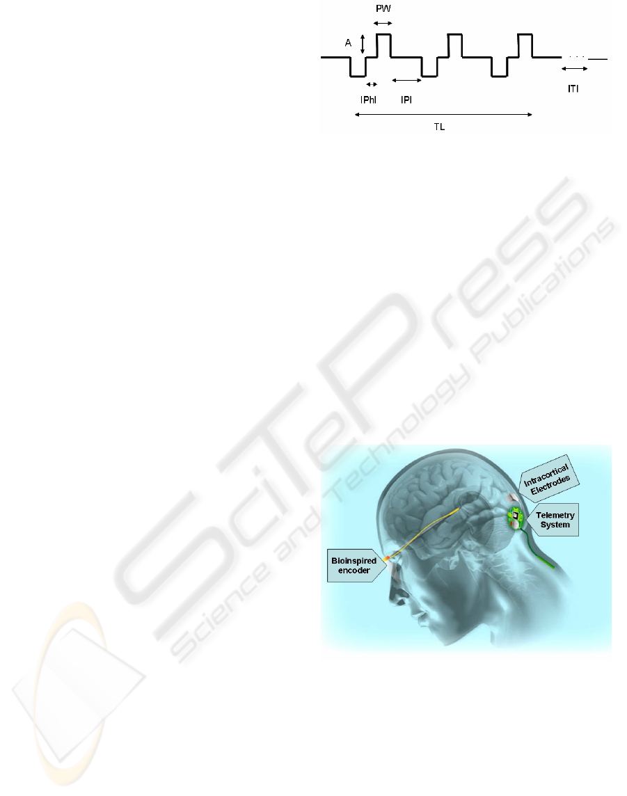
Figure1: Biphasic pulse train for cortical neurostimulation.
Pulse trains contain a number of parameters that can be
selected, as amplitude (A), pulse width (PW), inter-phase
interval (IPhI), interpulse interval (IPI), train length (TL),
and inter-train interval (ITI).
2 A VISUAL PROSTHESIS
MODEL
The platform described in this paper has been
developed to assist in the post-implantational stage
of research of a visual neuroprosthesis project. The
whole project, known as CORTIVIS (Cortical
Visual Neuroprosthesis for the Blind) (CORTIVIS,
2002), has been carried out by a consortium of seven
research labs and a small company under European
funding (see Fig. 2).
Figure 2: Scheme of the visual prosthesis proposed by
CORTIVIS. A camera grabs images, which are processed
by a bioinspired encoder. The encoder sends stimulation
commands wirelessly to the intracranial telemetry system.
Finally, the array of microelectrodes stimulates the visual
cortex of the subject.
The model selected for the CORTIVIS prosthesis
includes one or two cameras, as input, which feed a
bio-inspired retinal encoder, which partially replaces
the role of the visual processing taking place at the
retina, and determines the moment in which specific
implanted electrodes should be activated. The output
COMPUTER-CONTROLLED NEUROSTIMULATION FOR A VISUAL IMPLANT
85
of this stage is an address-event representation
(AER) indicating the number of electrode which will
be stimulated. This stream of addresses is sent
through a wireless link to the implanted section of
the prosthesis. The RF link also provides energy for
the implanted stimulator. This neurostimulator is
finally connected to an array of microfabricated
electrodes, which are inserted into the visual area of
the brain cortex. In our case, the Utah Electrode
Array (Normann, 1999), bearing 100 electrodes, has
been selected as the neuroelectrical interface.
3 RESEARCH PLATFORM
In this section, we describe the organization,
operation modes and capabilities of the research
platform we have developed for the testing and
tuning of cortical visual neuroprostheses.
3.1 System Architecture
Fig. 3 shows the building blocks that integrate the
experimenting station. A PC which runs the software
required to control the platform is connected to an
electronic neurostimulator. The connection is made
through one of the computer ports. Initially, we
employed the LPT port. However, the second
version of the neurostimulator is using a USB port to
exchange information with the PC. An opto-
coupling stage protects the patient against electrical
risks, as required for biomedical instruments.
The second stage of the platform is an electronic
equipment which receives and decodes commands
from the PC, according to a pre-established protocol.
This neurostimulator can receive configuration,
stimulation and test commands. Whenever a
configuration word is received, it stores the
waveform parameters for the corresponding channel
in a configuration memory. If a stimulation
command is sent from the PC, the equipment selects
the corresponding output channel through a
demultiplexor, and drives a Digital-to-Analog
converter so that a biphasic waveform is sent to the
output, according to the stored parameters for the
corresponding channel. Test commands just check
the state of the electronics, in order to detect
malfunctioning electrodes (due to encapsulation,
breakage during insertion, etc.).
The last block in the platform is the intra-cranial
implant, which is connected to the output of the
neurostimulator. In our case, we have selected the
Utah Electrode Array, which is a microfabricated
array of 10x10 microelectrodes (Fig. 4). This array
is pneumatically inserted into the brain cortex, so
that the tips of the electrodes are expected to reach
layer IV of the visual cortex. Previous experiences
have shown that electrical stimulation of cells in this
layer evoke visual percepts, similar to stars in the
night, which are called “phosphenes” (Schmidt,
1996).
In this acute clinical version of the CORTIVIS
prosthesis, a set of wires is used to connect the
stimulation equipment to the implant, discarding for
later use the radio-frequency link.
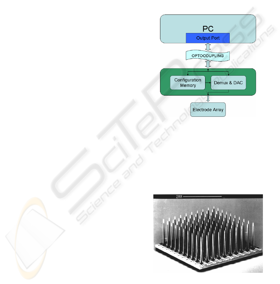
Figure 3: Structure of the research platform. A PC runs a
control software, and sends configuration and stimulation
commands through a PC port. An optocoupling stage
protects the patient against electrical risks. The next block
is the neurostimulation electronics. A configuration
memory stores the waveform parameters for every
channel, and a demultiplexing and digital-to-analog
convertion block issues the corresponding waveform, and
sends it to the proper electrode in the array.
Figure 4: the Utah Electrode Array (UEA). It is a 10x10
electrode matrix, bearing 1.5 mm tips, separated by 400
microns. It is microfabricated in silicon and platinum
(Normann, 1999).
BIODEVICES 2008 - International Conference on Biomedical Electronics and Devices
86
3.2 Operation Modes
The experimental set-up can present two different
configurations, called “stimulation” and
“simulation/training” modes.
The neurostimulation configuration corresponds
to the set described in section 3.1, that is, a PC
controlling a neurostimulator, which delivers pulses
to an implanted array of electrodes. The purpose of
this set is to allow researcher tuning the set of
parameters required to elicit phosphenes in the
visual field of the patient, and then, run a series of
psychophysical tests, in order to characterize the
evoked perceptions.
However, an alternative configuration is
available for debugging and training purposes (with
sighted volunteers). In this second choice, the
electronic neurostimulator and the implanted array
of electrodes are replaced by a second PC with head-
mounted displays. The first PC plays the same role
as in the previous configuration. The commands sent
through the communication port are received by the
second PC, which implements simulation rules
including random values for current threshold, and
phosphene location in the visual field. The simulator
in the second PC leads to a representation of a set of
phosphenes in a head mounted display, according to
the information obtained in similar experiences with
human visual intra-cortical microstimulation.
4 SOFTWARE CONTROL
The platform described in the former section runs a
program written in C++, under Microsoft Windows,
which controls all the automated procedures to be
carried out for stimulation parameter tuning and
psychophysical testing.
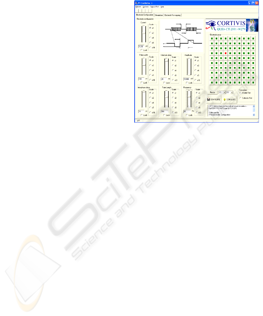
The control application, named “V1 Cortistim”
has a graphical user interface that allows the
experimenter to select every stimulation parameter
for the waveform, and run or stop every test.
However, in order to accelerate the lengthy process
of tuning the stimulation parameters for each
implanted electrode, and executing an extensive set
of psychophysical essays, every of these procedures
have been automated. This way, the patient becomes
the operator of the system, setting the pace of the
experimenting steps, and avoiding verbal interaction,
so the feedback given by the implanted individual by
means of the computer input mechanisms, is
automatically recorded, launching the next action of
the process. In the following sections, we detail the
procedures that are implemented in the research
platform.
Figure 5: V1 Cortistim Graphical User Interface, allowing
to control every waveform parameter for every channel in
the microelectrode array.
4.1 Current Threshold Finding
The first task after the patient has been safely
implanted is finding the lowest current amplitude
required to evoke a phosphene. This procedure has
to be done for every channel of the implant. This
way, the objective is to have as many phosphenes as
possible forming patterns of percepts, but injecting a
minimum amount of charge into the cortical tissue.
As mentioned before, this procedure is patient-
driven, so the response of the patient triggers the
next step of the process. The basic algorithm selects
every channel, and issues pairs of configuration and
stimulation commands to the stimulator with
increasing current amplitude, until the patient signals
the occurrence of a phosphene in his/her visual field,
by clicking a mouse button. Then, the process is
repeated for the next electrode.
We have included two modifications to this basic
search algorithm to reduce the number of total steps
required to complete the process. We have to take
into account that in a near future, next generations of
implants might include an amount of electrodes over
the thousand, and for each electrode a set of current
values should be tested, leading to a very tedious
and lengthy process. The first modification is
employing a binary search scheme, instead of a
linear model, reducing the complexity of the
problem. The second enhancement takes into
COMPUTER-CONTROLLED NEUROSTIMULATION FOR A VISUAL IMPLANT
87
account that current thresholds are expected to
gather around a mean value. Having this, we set the
starting point for the binary search for a channel to
the threshold found for the previous channel.
Applying this procedure, a set of 100 electrodes
can be configured in less than 5 minutes (for a step
of 1 second between consecutive stimulations).
A similar scheme can be applied to the rest of
parameters of the stimulation waveforms, although
most experimental implants take amplitude as the
main parameter. In any case, all the parameters are
interrelated, as they influence the amount of charge
injected, which is the main responsible for
phosphene evocation.
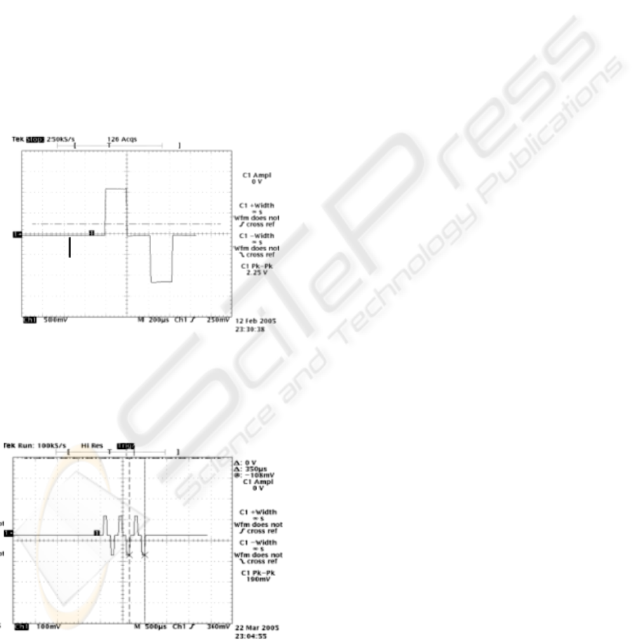
Experimental results of using the platform to
generate biphasic stimulation pulses are exposed in
Fig. 6 and in Fig. 7.
Figure 6: Example of biphasic pulse obtained with the
experimental neurostimulation platform (vertical scale:
500 mV/div; horizontal scale: 200 microsec/div).
Figure 7: Example of pulse train obtained with the
experimental neurostimulation platform (vertical scale:
100 mV/div; horizontal scale: 500 microsec/div).
4.2 Psychophysical Tests
After the threshold current has been determined for
every channel, a set of tests is required to be carried
out in order to characterize the psychophysical
properties of the evoked percepts.
This way, an extensive set of perceptual tests has
to be run, which again requires making this process
as easy and agile as possible. Following the same
philosophy as for the threshold finding procedure, a
patient-driven automated scheme is again employed.
The V1 Cortistim platform provides the
following set of psychophysical essays:
Brightness sensitivity: a change in certain
parameters of the waveform (mainly
amplitude) will modify the perceived
brightness of the evoked phosphene. A pair of
phosphenes is elicited, and the brightness of
one of them changes until the patient finds no
change.
Spatial resolution: a pair of phosphenes
produced by distant electrodes is evoked
consecutively with closer and closer
electrodes until the patient cannot differentiate
them.
Phosphene cluster count: a set of 1, 2 or 3
phosphenes from adjacent electrodes is
elicited. The patient gives feedback on the
number of phosphenes perceived.
Motion mapping and orientation selectivity: a
straight line of electrodes (row, column or
diagonal) in the matrix consecutively get
activated. The patient indicates the general
direction of apparent motion of the phosphene.
Simple pattern discrimination: a simple pattern
(similar to Snellen symbols) and its
“mirrored” pattern are consecutively activated
in the electrode array. The subject tells if they
seem to be different or similar.
5 PHOSPHENE MAPPING AND
RE-MAPPING
A key aspect in the design of a phosohene-based
visual neuroprosthesis is the ability to evoke patterns
of percepts that can be matched to known models
from the visual world.
Experiments both with human and non-human
subjects have shown that the correspondence
between the spatial location of the stimulation point
in the cortex and the position of the evoked
BIODEVICES 2008 - International Conference on Biomedical Electronics and Devices
88

phosphene in the visual field can present strong
deformations (Normann, 2001).This is especially
remarkable for high density arrays of electrodes, in
which the correspondence between the stimulation
and the perceptual spaces is highly non-linear and
non conformal. This fact might be caused by the
complex interconnections among the neural cells
that respond to stimulation in the area of influence of
an electrode. Anyway, a mapping between the
location of the activated electrode and the position
of its corresponding phosphene in the visual field
should be built for every channel of the implant.
Correspondingly, an inverse transformation or re-
mapping, indicating which electrodes should be
activated to get a specific pattern of phosphenes is
required in order to evoke recognizable percepts. We
describe the solutions implemented for our
experimentation platform both for the mapping and
re-mapping objectives.
5.1 Phosphene Mapping
Several mapping methods have been used for
building a table to determine the spatial coordinates
of a phosphene corresponding to the activation of
every electrode, as joysticks, dartboards or digital
tablets. Our objective in this procedure is not only,
as before, to obtain an agile system by avoiding
verbal interaction, and by having an automated
patient-driven process, but also achieving precision
in a process that is very prone to inaccuracy.
Our platform includes a mapping process based
on a tactile screen placed just in front of the patient,
as exposed in Fig. 8. A consecutive pair of
phosphenes is elicited, and the patient touches the
tactile screen in the points in where the percepts
appear on the visual field. The platform, in training
mode, is able to find out the mapping error, as the
real location of the evoked phosphenes in the head
mounted displays is computer-generated, and can be
compared to the position pointed out by the subject.
Figure 8: Example of usage of the automated phosphene
mapping system. The platform is being used in training
mode. A sighted volunteer wearing Head Mounted
Displays perceives computer-generated phosphenes, and
indicates their location on his visual field by touching a
tactile screen in front of him.
5.2 Re-mapping Procedure
Once an electrode-to-phosphene map is available, a
pattern of phosphenes can be elicited by stimulating
the corresponding electrodes. So, whenever a
specific distribution of phosphenes is required in the
visual field of the patient, a list of electrodes has to
be determined. This process is called re-mapping.
The map of phosphenes elicited with intra-
cortical microstimulation appears to be stable for a
given patient (Schmidt, 1996). However, there are a
limited number of phosphenes available in specific
locations of the visual field, which have to be used
to evoke any desired pattern.
Our first approach is to project the desired
pattern on the center of the visual field, and then,
select, for every desired point, the closest phosphene
to it. With a reverse look up at the mapping table, its
corresponding electrode is found.
Instead of selecting the absolutely closest
phosphene in the map to the desired point, we
choose the closest phosphene which hasn’t already
been selected. That way, we can obtain patterns
including a maximum number of phosphenes, rather
than having more precise locations with less
percepts. Although the patterns can present some
more deformation, its completeness, along with the
training of the patient, is expected to lead to a better
recognition, as illustrated in Figs. 9 and 10.
Additionally, this selection procedure enhances
the response whenever the distribution of the map is
highly uneven. So, in the case we have a region of
the visual field covered by a small group of
phosphenes, and another region with a high density
of percepts, a moving object in the visual field
should be composed of the same number of
phosphenes. Direct selection of the closest
phosphene would lead to a different number of
points in a pattern, depending on the location of the
object in the visual field (which makes difficult, for
example, recognize a moving object as a unit). With
our algorithm, an object is always composed of the
same number of phosphenes, regardless of its
location in the visual field. The shape of the pattern
can vary, in an effect similar to looking a moving
objective through a frosted glass.
COMPUTER-CONTROLLED NEUROSTIMULATION FOR A VISUAL IMPLANT
89

Figure 9: Phosphene pattern that would be elicited after
direct selection of the top row and central column of an
electrode array. Although the distribution of electrodes
forms a “T” shape, the evoked pattern is unrecognizable,
so a remapping is required. This set of phosphenes
corresponds to a randomly generated mapping (25x25).
Figure 10: after our remapping algorithm is applied to the
previous figure, a different set of electrodes are activated,
yielding a better recognizable pattern of phosphenes,
closer to the desired “T” shape.
6 ADDITIONAL TOOLS FOR
VISUAL NEUROPROSTHETICS
The platform described in this paper is a specific
design for the clinical testing stage of a complete
visual neuroprosthetic system.
However, corresponding to the whole system
architecture depicted in Fig. 2, some other relevant
blocks are required for achieving a complete,
portable visual prosthesis.
Regarding this point, we give a brief reference of
additional platforms and hardware/software tools
developed to contribute to the complete prosthetic
system. Details of every one of them can be found
elsewhere.
Direct stimulation of the visual cortex requires,
somehow, replacing the image processing carried
out by earlier stages of the visual pathway, such as
the spatio-temporal filtering performed by the retina.
For this purpose, a retina-like processing
software platform has been developed in Matlab,
which allows experimentation with an extensive set
of parameters, so that a video or live camera capture
can be processed, and the electrode firings
(corresponding to the activity of retinal ganglion
cells) are obtained. This way, the response of our
artificial retina can be compared to the one given by
biological retinae when exposed to the same stimuli.
Further information can be found at (Pelayo,
2004).
A second objective of the CORTIVIS project is
to achieve a portable, low power consumption
version of the previous retinal pre-processor, so that
the patient can wear a camera mounted on
eyeglasses frame, and the processor will transmit
activation commands to the corresponding channels
of the intra-cranial segment of the implant via a
wireless link.
A plug-in module for the Retiner program has
been built, which is able, to translate the retinal
model designed with our software into a
configuration file for a programmable logic chip, so
that all the retinal processing is carried out by a
single, portable integrated circuit. References can be
found at (Martínez, 2005).
7 CONCLUSIONS
We present a computer-controlled platform
conceived to control a neural interface. The main
objective is to provide a friendly and automated way
of performing experiments after implantation of an
array of microelectrodes into the visual cortex of a
patient. The platform serves as interface to handle
the complexity inherent to a multi-channel brain-
computer link that requires tuning biphasic
stimulation pulse trains for every electrode.
Every experimental procedure is automated, and
patient-driven, in order to make the tuning and
testing process as fast as possible. The platform
includes a set of psychophysical tests to determine
key features of the electrically evoked percepts.
As previous micro-stimulation experiences
confirm, the elicited patterns of phosphenes suffer
strong deformations with respect to the distribution
of the corresponding electrodes in the array. As the
objective is to evoke recognizable patterns, a re-
organization (re-mapping) between the stimulation
and perceptual spaces is required. Our platform
includes a re-mapping algorithm for such a purpose.
We also make a brief reference to some additional
tools developed by our research group, also
BIODEVICES 2008 - International Conference on Biomedical Electronics and Devices
90

contributing to the development of a complete
independent prosthetic system. These tools include a
flexible retinal processing model, an automatic
synthesizer to program integrated circuits for retinal
processing, and a system to include binocular and
spatial information in the set of stimuli sent to the
brain.
Unfortunately, it is difficult to provide a detailed
and standardized comparison against other systems
under development. On one hand, these kinds of
systems are specifically designed and fitted to
control a particular implant, so no compatibility
criteria are considered. On the other hand, as
neuroengineering is a young field of research, no
standards for measuring and comparing the
performance of a prosthetic system are available.
Nevertheless, some relevant organizations
involved in blindness and low vision research, as the
ARVO (ARVO, 2007), or the Smith-Kettlewell Eye
Research Institute (SKERI, 2007), are organizing
and conducting specific meetings aiming to arrive to
a standardized set of tests that will be useful to
provide a measurement of the performance of these
implants.
ACKNOWLEDGEMENTS
This work has been carried out with the support of
the European project CORTIVIS (ref. QLK6-CT-
2001-00279), the National Spanish Grants
DEPROVI (ref. DPI 2004-07032), IMSERSO-
150/06, and by the Junta de Andalucía Project: P06-
TIC-02007.
REFERENCES
ARVO (Association for Research in Vision and
Ophthalmology) website. Available online at:
http://www.arvo.org.
Cha, K., Horch, K. W., & Normann, R. A. 1992 Mobility
performance with a pixelized vision system. Vision
Research (32): 1367–1372.
CORTIVIS, 2002. CORTIVIS project website. Available
online at: http://cortivis.umh.es.
Dobelle, W. H., 2000. Artificial Vision for the Blind by
Connecting a Television Camera to the Visual Cortex.
American Society of Artificial Internal Organs
(ASAIO) Journal (46):3-9.
Fernández, E., Pelayo, F., Romero, S., Bongard, M.,
Marin, C., Alfaro, A., Merabet, L. 2005. Development
of a cortical visual neuroprosthesis for the blind: The
relevance of neuroplasticity. Journal of Neural
Engineering (4): R1-R12.
Humayun, M. S., 2003. Visual perception in a blind
subject with a chronic microelectronic retinal
prosthesis. Vision Research 43 (24): 2573-2581.
Martínez A., Reyneri L. M., Pelayo F. J., Romero S.,
Morillas C. A., and Pino B. 2005. Automatic
generation of bio-inspired retina-like processing
hardware. Lecture Notes in Computer Science (3512):
527–533.
Moore, R., Lopes, J., 1999. Paper templates. In
TEMPLATE’06, 1st International Conference on
Template Production. INSTICC Press.
Normann, R. 1999. A neural interface for a cortical vision
prosthesis. Vision Research.(39): 2577-2587.
Normann, R.A., Warren, D.J., Ammermuller, J.,
Fernandez, E., Guillory, S. 2001. High-resolution
spatio-temporal mapping of visual pathways using
multi-electrode arrays. Vision Research (41): 1261-
1275.
Pelayo F. J., Romero S., Morillas C., Martínez A., Ros E.,
Fernández E., 2004. Translating image sequences into
spikes patterns for cortical neuro-stimulation.
Neurocomputing (58-60): 885–892.
Schmidt, E.M., Bak, M, Hambrecht, F.T., Kufta, C.V.,
O'Rourke, D.K., and Vallabhanath, P. 1996.
Feasibility of a visual prosthesis for the blind based on
intracortical microstimulation of the visual cortex.
Brain (119): 507-522.
SKERI (Smith-Kettlewell Eye Research Institute) website.
Available online at: http://www.ski.org.
Troyk, P. et al., 2003. A Model for Intracortical Visual
Prosthesis Research. Artificial Organs (11):1005–
1015.
Veraart, C., 1998. Visual sensations produced by optic
nerve stimulation using an implanted self-sizing spiral
cuff electrode. Brain Research (813):181-186.
WHO (World Health Organization), 2005. Prevention of
avoidable blindness and visual impairment, Available
on-line: http://www.who.int/gb/ebwha/pdf_files/
EB117/B117_35-en.pdf.
COMPUTER-CONTROLLED NEUROSTIMULATION FOR A VISUAL IMPLANT
91
