
POLYMER MEMS SYSTEM FOR MEASURING THE
MECHANICAL MODULUS OF A BIOLOGICAL CELL
Wenyue Zhang
1
, Markus Gnerlich
1
, Yaohua Sun
1
, Gaoshan Jing
1
, Jonathan J. Paly
2
Arkady Voloshin
2,3
and Svetlana Tatic-Lucic
*1,2
1
Sherman Fairchild Center, Electrical & Computer Engineering Department
2
Bioengineering Program
3
Department of Mechanical Engineering & Mechanics, Lehigh University, Bethlehem, Pennsylvania 18015, USA
Keywords: Cell mechanics, mechanical modulus, MEMS, polymer, dielectrophoresis.
Abstract: The measurements of the mechanical modulus of biological cells are critical to studies of pathophysiology
and the research for an effective treatment. This research has developed a rapid and cost effective technique
in order to measure the Poisson’s ratio and mechanical modulus of a live biological cell by utilizing
microelectromechanical system (MEMS) techniques in a biological application. The design, fabrication,
and characterization of a polymer-based MEMS system that integrates a V-shaped electrothermal actuator
array and a cell-positioning system in a single microelectronics chip are presented here. This BioMEMS
device compressed a NIH3T3 fibroblasts cell and caused up to 25% mechanical strain.
1 INTRODUCTION
Osteoporosis is a pubic health problem that affected
more than 44 million Americans in 2004, most of
them are women and/or seniors (U.S. Department of
Health and Human Services, 2007). This age-related
disease results in bones that lack the ability to
respond to dynamic mechanical stimulus, which is
required for the bones in the human musculoskeletal
system to maintain proper osteogenesis (Fritton,
McLeod, and Rubin, 2000). Since several properties
of bone cells, such as adaptation (Caillot-Augusseau,
Lafage-Reoust, Soler, Pernod, Dubois, and
Alexander, 1998) and the cytosolic calcium response
to fluid flow (Donahue, Zhou, Li, and McCauley,
1997), have been proven to decrease as a function of
age, biologists hypothesize that the biomechanical
properties of osteoblasts (bone-formation cells)
change as a function of age, and this change could
be a contributing factor to the pathogenesis of
osteoporosis (You, Yellowley, Donahue, Jacobs,
1999).
However, this hypothesis has not been carefully
examined due to the limitations of current
measurement techniques, such as atomic force
microscopy (AFM), which tests the mechanical
properties of one small portion of the cell, and can
only test one cell at a time. Testing cells one-by-one
is too time-consuming and expensive to be
commonly practiced in biological research, which
relies on statistical studies that require surveying a
large number of cells. As a result, the mechanism
underlying the pathophysiology of osteoporosis is
still unknown.
To improve the public health condition, it is
absolutely necessary to develop efficient techniques
to measure cell’s mechanical properties. Recently,
several MEMS devices have been applied to
biological researches, such as a MEMS-based force
sensor (Yang and Saif, 2006), and a frequency
depedent electrostatic actuator (Scuor, Gallina,
Panchawagh, Mahajan, and Sbaizero, 2006).
Compared to these single crystal silicon and
polysilicon devices, polymer devices have several
advantages, such as: less possibility of damaging
live cells when making physical contact due to the
low Young’s modulus of polymers; lower cost
(Elderstig and Larsson, 1997); and lastly, the ability
to operate in liquids if an electrothermal actuation
mechanism is used (the heat is insulated due to the
low thermal conductance of polymers). This paper
reports a polymer-based MEMS system for
measuring the mechanical properties of a live cell.
146
Zhang W., Gnerlich M., Sun Y., Jing G., J. Paly J., Voloshin A. and Tatic-Lucic S. (2008).
POLYMER MEMS SYSTEM FOR MEASURING THE MECHANICAL MODULUS OF A BIOLOGICAL CELL.
In Proceedings of the First International Conference on Biomedical Electronics and Devices, pages 146-150
DOI: 10.5220/0001052201460150
Copyright
c
SciTePress
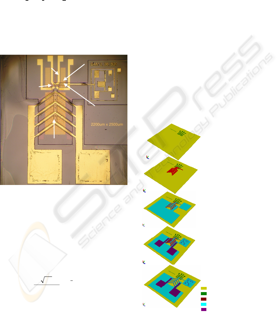
2 METHODOLOGY
To measure the mechanical modulus of a biological
cell, a BioMEMS device was designed and
fabricated (Figure 1). In a 2.2 x 2.5 mm
2
single chip,
a polymer electrothermal actuator (ETA) array (1) is
to compress a live cell agaist a fixed wall (2), and
report associated forces and displacements during
the compression. In addtion, a cell positioning
system (dielectrophoresis quadrupole electrodes (3))
is used to trap a cell at a desired location, and a set
of scale bars (4) is used to calibrate the optical
measuring system.
Figure 1: Optical image of a fabricated BioMEMS device
for measuring the mechanical modulus of a biological cell.
Four experimental steps need to be done before
obtaining the mechanical properties of a cell: (a)
characterizing the actuator displacement as a
function of input electrical power; (b) determining
the reaction force between the actuator and the cell;
(c) recording the force versus deformation curve for
the cell; (d) fitting the curve with equation (1),
which which was based on the derived Hertz contact
model (Timoshenko and Goodier, 1970):
2
3
2
)1(3
22
d
Ed
F Δ
⎟
⎟
⎠
⎞
⎜
⎜
⎝
⎛
−
=
νπ
(1)
where
F was the applied force to a cell, ∆d was cell
deformation,
E was compressive modulus of the cell,
d was the diameter of a cell, and ν was the Poisson’s
ratio of the cell. The fitted parameter reveals the
mechanical modulus of the cell.
3 MEMS DEVICE FABRICATION
Fabrication of the MEMS devices utilized surface
micromachining techniques. The processing flow
has been described in detail previously (Zhang,
2007), and will be briefly summarized here (Figure
2). The starting materials are oxidized 3-inch
diameter silicon wafers. First, a metal layer of
80 nm platinum was patterned using lift-off process
(Figure 2a). A 20 nm titanium layer preceding this
conductive layer was used to increase the adhesion
wherever metallization was present. Second, a 5 µm
thick sacrificial photoresist (AZ P4620, Clariant,
New Jersey) was applied to create an air gap (Figure
2b). Third, a thick negative tone photoresist (SU-8,
product #: 2015, Microchem, MA) was used for a
structural layer (Figure 2c). Next, the second metal
layer of 80 nm gold (with the same adhesion layer)
was patterned on top of the structural polymer
(Figure 2d). Finally, the whole structure was
immersed in AZ 400T photoresist stripper (Clariant,
New Jersey) at room temperature to release the
polymer device (Figure 2e).
Figure 2: Fabrication process flow for the BioMEMS
device for measuring the mechanical modulus of a
biological cell.
a) Deposit and
pattern the first metal
layer (Pt/Ti) on a
glass (or oxidized
silicon) wafer
b) Deposit and
pattern the sacrificial
la
y
er
(
AZ P4620
)
c) Deposit and
pattern the structural
la
y
er
(
SU-8
)
d) Deposit and
pattern the second
metal la
y
er
(
Au/Ti
)
e) Release the structural
layer by removing the
sacrificial layer
Substrate (Oxidized Silicon)
1
st
Metal Layers (Pt/Ti)
Sacrificial Layer (AZ P4620)
Structural Layer (SU-8)
2
nd
Metal La
y
e
r
s
(
Au/Ti
)
(2) Fixed wall
Oxidized Silicon
substrate
(1) Polymer ETA
array
(4) Scale bars
Cell location
(3) dielectrophoresis
quadrupole electrodes
POLYMER MEMS SYSTEM FOR MEASURING THE MECHANICAL MODULUS OF A BIOLOGICAL CELL
147
3.1 Effects of UV/Ozone Treatment
A UV/Ozone cleaner was used to clean the
substrates and harden the sacrificial pattern (AZ
P4620). Without this step, the sacrificial pattern was
destroyed during the spin-coating of the structural
SU-8 polymer (Figure
3) by centrifugal forces and/or
solvent diffusion. During the UV/Ozone treatment,
the deep UV light (in ranges of 185 nm to 254 nm
wavelength) hardened the thick sacrificial
photoresist (Allen, Foster, and Yen, 1982) while the
heat generated by the UV lamps added additional
cross-linking. Therefore, the sacrificial patterns can
maintain their shapes after SU-8 patterning. We
used polymer sacrificial materials because it was too
difficult to selectively remove a metal sacrificial
layer with the pre-patterned Pt/Ti layer on the
substrate.
Figure 3: Optical images of the sacrificial patterns (a)
before and (b) after spin-coating a transparent structural
layer. These sacrificial patterns did not have UV/Ozone
treatment and were destroyed.
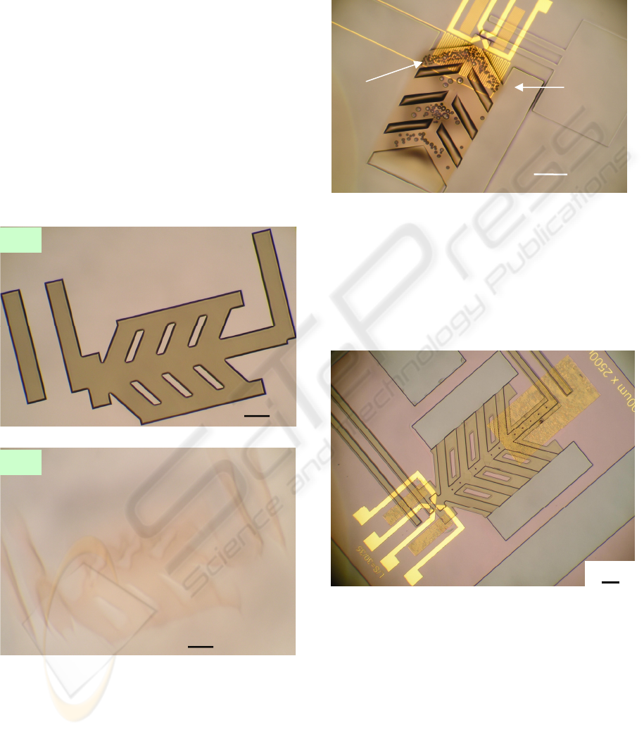
One more benefit of an UV/Ozone treatment was
reduction of gas bubbles in the resist. During the
UV exposure of SU-8, the underlying AZ P4620 that
had not been previously exposed also absorbed UV
radiation. Then, gases due to photoresist outgassing
in UV light (Kunz, 2004) were trapped by the SU-8
layer, which causes gas bubbles formation (Figure
4).
Figure 4: Optical image of gas bubbles that appeared the
post exposure baking after UV exposure of the structural
layer (SU-8).
Short UV/Ozone treatment (3 to 4 minutes) was
applied to solve the gas bubbles problem and
resulted in a sacrificial pattern hard enough to resist
physical and chemical damage (Figure 5), but still
able to be removed at the end of processing.
Figure 5: Optical image of a fabricated device. After
selecting the proper UV/Ozone treatment time, the
sacrificial patterns keep their shapes after SU-8 patterning.
(This image was taken after developing the SU-8 layer but
before the second metal layer formation).
4 RESULT & DISCUSSION
High frequency (800 KHz, sinusoidal) AC voltages
were applied to these BioMEMS devices to avoid
electrolysis, which generates a large amount of gas
in liquids (Selvaganapathy,
Leung Ki, Renaud, and
100 µm
Gas
bubbles
SU-8
Pattern
100 µm
The AZ P4620 pattern
was destroyed during
s
p
in-coatin
g
of the SU-8
(
b
)
The AZ P4620
pattern before spin-
coating of the SU-8
(
a
)
100 µm
100 µm
BIODEVICES 2008 - International Conference on Biomedical Electronics and Devices
148
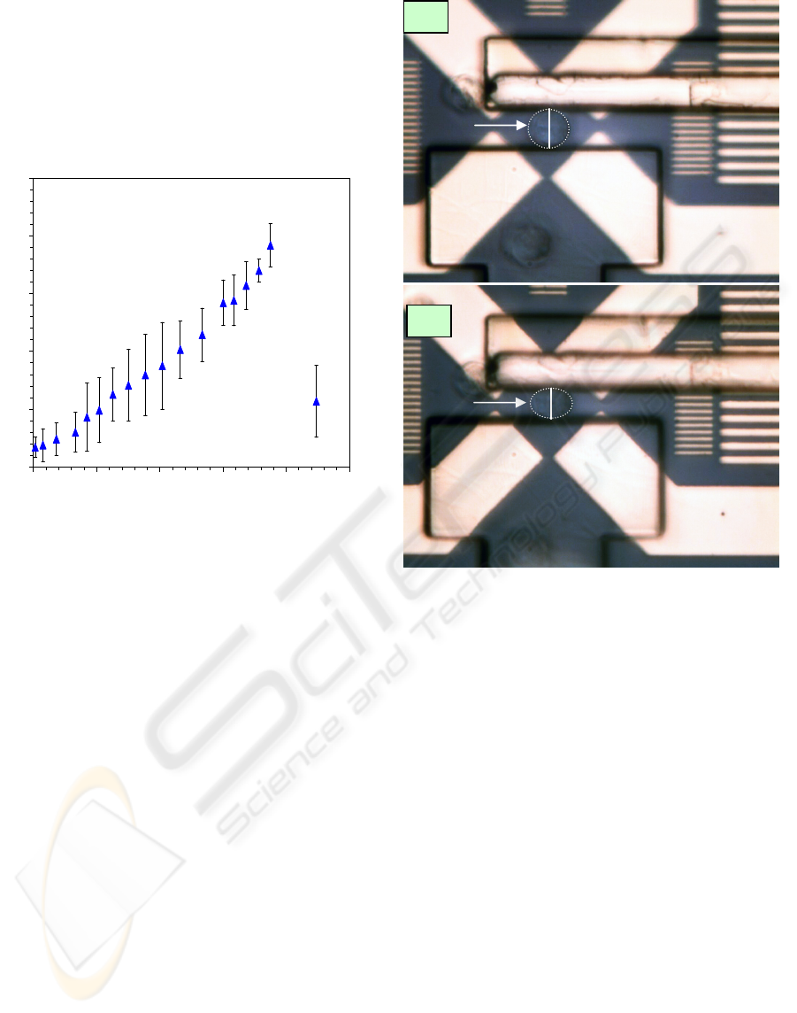
Mastrangelo, 2002). The actuator displacement as a
function of input electrical power was recorded
(Figure 6) when operation in NIH3T3 fibroblasts
cell medium. The maximum displacement was
4 µm when power was RMS 750 mW. After
exceeding the maximum value, the displacement
decreased due to the out-of-plane deformation of the
polymer V-shaped electrothermal actuator array.
Figure 6: Experimental data of the BioMEMS ETA arrays’
displacement as a function of input AC power.
The lab experiments started with immersion of the
BioMEMS device into the cell medium. Cells were
transferred to the device using a micropipette. First,
a cell was trapped at the centre of the
dielectrophoresic quadrupole electrodes after
applying an AC voltage (10 V
p-p
, 1 MHz, sinusoidal)
to them (Figure 7a). Next, the actuator was moved
towards the cell, and it compressed the cell up to
4 µm (Figure 7b). The diameter of the cell under
test was measured to be 16 µm. This means that the
BioMEMS devices can mechanically stimulate the
cell in 25% strain, which is double the minimum
requirement (10% strain) of mechanical stimulation
to a cell (You, Cowin, Schaffler, and Weinbaum,
2001).
When the cell was under compression,
orthogonal extension was observed as well.
Currently, the displacement resolution was ±0.5 µm.
Next, the spring constant of the polymer ETA was
calibrated using a nanoindenter (TriboScope,
Hysitron Inc.). Finally, the compressive modulus of
the NIH3T3 fibroblast cell can be extracted from
these measurements. In order to extract reliable
mechanical modulus, we are currently working on
improving the resolution of this method.
Figure 7: Optical images of: (a) a cell being trapped at the
centre of dielectrophoresic quadrupole electrodes, and (b)
the cell being compressed by the actuator after being
powered up. (Outline of the cell is for better visibility.).
5 CONCLUSIONS
The measurements of the mechanical properties of
biological cells are critical to improve the public
health condition. This research focuses on the
design, fabrication, and characterization of a MEMS
system to measure the compressive modulus of a
live biological cell. This MEMS-based system has
realized three basic functions: (1) trapping a cell to a
designed area before testing; (2) applying forces to a
cell, and (3) sensing the forces and displacements
during the compressing. The device was able to
compress a cell up to 25% mechanical strain in a cell
medium. The measurements of mechanical
properties are limited by the current displacement
resolution and the improvements are under
investigation.
Fixed wall
(a)
A
c
t
ua
t
or
Cell
DEP
Electrodes
16 μm
Cell
A
c
t
ua
t
or
Fixed wall
DEP
Electrodes
(b)
12 μm
0
1
2
3
4
5
0 200 400 600 800 1000
AC Power RMS [mW]
Displacement [
μ
m]
POLYMER MEMS SYSTEM FOR MEASURING THE MECHANICAL MODULUS OF A BIOLOGICAL CELL
149

REFERENCES
Allen, R., Foster, M., Yen, Y.-T., 1982. Deep U.V.
Hardening of positive photoresist patterns. J
Electrochem. Soc., 128, 1379.
Caillot-Augusseau, A., Lafage-Reoust, M.-H., Soler, C.,
Pernod, J., Dubois, F., Alexander, C., 1998. Bone
formation and resorption biological markers in
cosmonauts during and after a 180-day space flight
(Euromir 95). Clin. Chem. 44(3), 578-585.
Donahue, H. J., Zhou, Z., Li, Z., McCauley, L. K., 1997.
Age-related decreases in stimulatory G protein-
coupled adenylate cyclase activity in osteoblastic cells.
Am. J. Physiol. 273, E776-E781.
Elderstig, H., Larsson, O., 1997. Polymeric MST-high
precision at low cost. J. Micromech. Microeng., 7, 89-
92.
Fritton, S. P., McLeod, K. J., Rubin, C.T., 2000.
Quantifying the strain history of bone: spatial
uniformity and self-similarity of low-magnitude
strains. J. Biomechanics. 33 (3), 317-325.
Kunz, R. R., 2004. Photoresist outgassing: a potential
Achilles heel for short wave-length optical lithography?
in Proc. of SPIE, 5376, 1-15.
Scuor, N., Gallina, P., Panchawagh, H. V., Mahajan, R.
L., Sbaizero, O., 2006. Design of a novel MEMS
platform for the biaxial stimulation of living cells.
Biomed. Microdevices, 8, 239-246.
Selvaganapathy, P., Leung Ki, Y.-S., Renaud, P.,
Mastrangelo, C. H., 2002. Bubble –free electrokinetic
pumping. J. Microelectromech. Syst., 11(5), 448-453.
Timoshenko, S.P. and Goodier, J.N., 1970. Theory of
Elasticity. 3rd ed. New York: McGraw-Hill Publishing
Company. 409-415.
U.S. Department of Health and Human Services, (2007).
Bone Health and Osteoporosis: A Report of the
Surgeon General. Retrieved July 9, 2007, from
http://www.surgeongeneral.gov/library/bonehealth/fac
tsheet2.html
Yang, S., Saif, T., 2006. MEMS based sensors for the
study of indentation response of single cells. in Tech.
Dig. of MEMS 2006, Istanbul, Turkey, 20-23.
You, J., Yellowley, C. E., Donahue, H. J., Jacobs, C. R.,
1999. Physiological levels of substrate deformation are
less stimulatory to bone cells compared to fluid flow,
In American Society of Mechanical Engineers,
Bioengineering Division (Publication) BED, 43, 161-
162.
You, L., Cowin, S. C., Schaffler, M. B., Weinbaum, S.,
2001. A model for strain amplification in the actin
cytoskeleton of osteocytes due to fluid drag on
pericellular matrix. J. Biomechanics. 34 (11), 1375-
1386.
Zhang, W.-Y., 2007. Design, Modeling, Fabrication and
Characterization of a MEMS Device for Measuring
the Mechanical Compliance of a Biological Cell. Ph.D.
Dissertation, Lehigh University, 2007.
BIODEVICES 2008 - International Conference on Biomedical Electronics and Devices
150
