
PATIENT SIMULATOR APPLIED TO AUDITORY EVOKED
POTENTIALS, ELECTROCARDIOGRAPHY AND
ELECTRONYSTAGMOGRAPHY
M. Tavares, C. Richter
Biomedical Engineering Laboratory, Catholic University of Pelotas, Rua Felix da Cunha 412, Pelotas, Brazil
R. Moraes
Electric Eng. Department, Federal University of Santa Catarina, Campus Universitário Trindade, Florianópolis, Brazil
T. Oliveira
PDI, Contronic Sistemas Automaticos Ltda.,Rua Rudi Bonow, 275, Pelotas, Brazil
Keywords: Simulator, AEP, ECG, ENG, electro-medical equipments maintenance.
Abstract: This paper describes an electronic device, named SimPac I, developed to simulate auditory evoked
potentials of short, middle and long latencies, ECG and electronystagmography signals. It uses sampled
waveforms in order to better reproduce real physiologic AEPs. The simulator is based on the ADuC841
microconverter, a device with an 8052-like core, FLASH memory and two 12-bit DACs. SimPac I is
portable and easy to operate, and it is very useful for calibration of AEP, ECG, ENG and VENG systems
during manufacture and maintenance. The simulator can also be used to support development and testing of
DSP algorithms intended to filter and/or average the above mentioned signals. As a result, examples of
several waveforms generated by SimPac I are shown.
1 INTRODUCTION
The auditory evoked potentials (AEP) play a
fundamental role in the audiology practice. The
capacity of capturing electric potentials generated in
response to acoustic stimulations resulted in many
relevant applications to the oto-neurologist (Katz,
1999). AEPs are classified in agreement with its
latency. Potentials of short latency occur in up to 10
ms after the auditory stimulation. Middle latency
potentials occur between 10 ms and 100 ms after the
stimulus, and long latency potentials are registered
after 100 ms from the stimulus. Short latency AEPs
are known by the acronyms BAEP – Brainstem
Auditory Evoked Potentials, BERA – Brainstem
Electric Response Audiometry or ABR - Auditory
Brainstem Response (Chiappa, 1997). The
electrocochleography (EcochG), used for cochlear
evaluation, is also considered a short latency AEP.
ABR is used for evaluation of the brainstem
integrity and also for objective audiometry. Middle
latency evoked potentials are identified with the
acronyms MLR or MLAEP (Middle Latency
Auditory Evoked Potential). MLAEP is indicated to
evaluate dysfunctions that could commit the hearing
pathways located between the brainstem and the
primary cortex.
P300 and MMN (Mismatch Negativity) are the
most used long latency AEPs in the clinical practice.
P300 presents a positive peal around the 300 ms
latency and using it makes it possible to obtain, in
only one test, information about the activity of the
transition thalamus-auditory cortex, the own
auditory cortex, about the hippocampus, hearing
attention and cognition. P300 is elicited through a
"rare paradigm", in which a few "rare" stimuli
happen randomly in a series of "frequent" stimuli.
The difference between both can be the intensity or
the frequency. The MMN test uses also rare and
frequent stimulus, but the result reflects the central
processing capacity (Caovilla, 2000).
130
Tavares M., Richter C., Moraes R. and Oliveira T. (2008).
PATIENT SIMULATOR APPLIED TO AUDITORY EVOKED POTENTIALS, ELECTROCARDIOGRAPHY AND ELECTRONYSTAGMOGRAPHY.
In Proceedings of the First International Conference on Biomedical Electronics and Devices, pages 130-134
DOI: 10.5220/0001052701300134
Copyright
c
SciTePress
ECG is certainly the most known bioelectric signal
generated by the human body. That signal is
captured and analyzed for use in clinical diagnosis,
surgical accompaniment and rehabilitation. Several
types of ECG simulators exist, able to simulate
changes in amplitude, heart beat frequency and many
types of arrhythmias (Prutchi and Norris, 2005).
They find application in the project of new monitors
and in the preventive and corrective maintenance.
The perfect corporal balance is very important
for the living organism orientation in the
environment. That balance widely depends on the
vestibular system, which acts in cooperation with the
visual system to maintain the vision focus during
head movements. The cerebral system that makes it
possible is known as vestibulo-ocular reflex (VOR).
The electric evaluation of VOR is done through the
electronystagmography exam (ENG) or by its
variant, the vector-electronystagmography (VENG)
(Castagno et al., 1994). The evaluation of
ENG/VENG is based on the registration and analysis
of the nystagmus, that is, the reflex ocular
movements which happen when the labyrinth
receive caloric or rotational stimuli.
The proposed Patient's Simulator was called
SimPac I and incorporates the technological
solutions used in the previously developed prototype
SPEA (Freitas et al., 2006). SimPac I has the
purpose of serving as a tool for development,
validation, adjustment and maintenance of AEP,
ECG and ENG/VENG equipments.
2 MATHERIALS AND METHODS
SimPac I is able to generate in two channels all of
the short, middle and long latency AEP waveforms
mentioned in the introduction. The morphology of
those signals was shown in a previous paper (Freitas
et al., 2006). Real signals of AEP were scanned to
obtain 500 samples for each one, and after they were
digitally processed in order to ensure the use of
whole the dynamic range of the 12-bit D/A
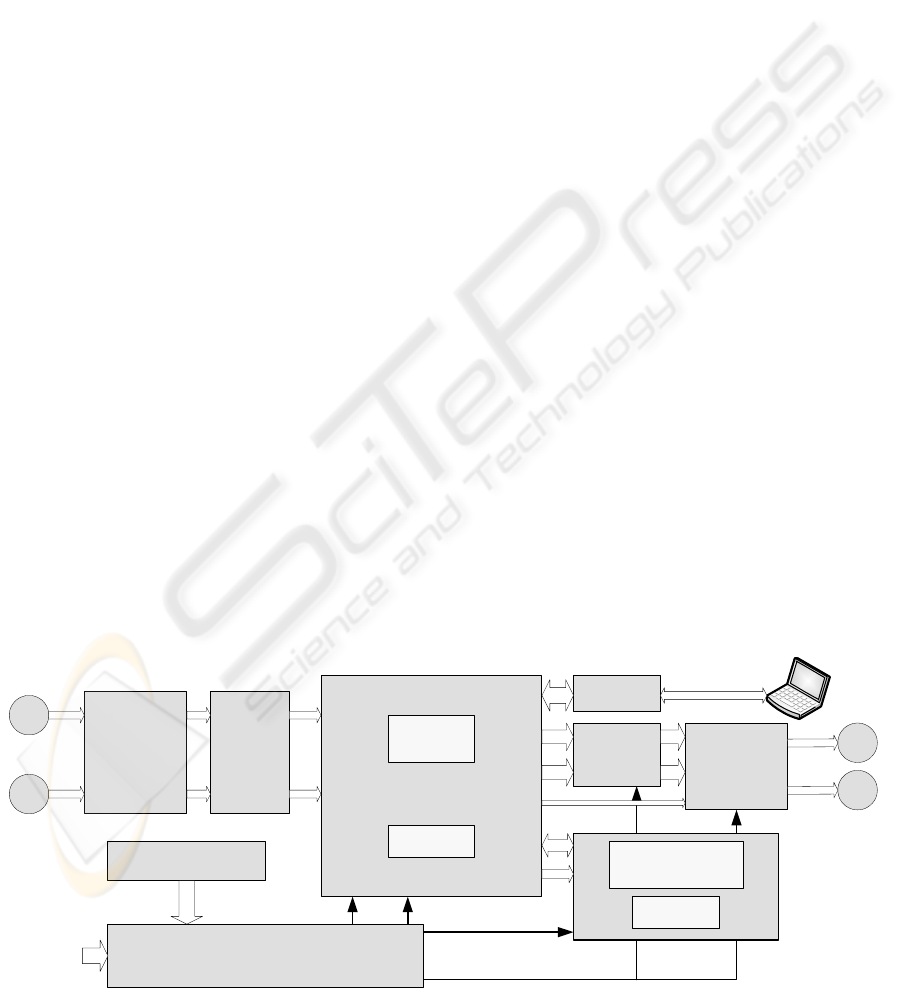
converters present in the simulator. Figure 1
contains the blocks diagram of SimPac I. The main
hardware component is the microconverter (µC)
ADuC841 (Analog Devices, 2003), whose CPU is
compatible with Intel’s 8052, modified to execute
instructions to 20 MIPS peak. The simulator does
not require external memories, since it uses only the
µC internal program FLASH and internal RAM.
ADuC841 is responsible for waveforms generation
using DDS technique (Digital Direct Synthesis),
starting from the sample tables stored in FLASH
memory (Grover and Deller, 1999). Energy is
provided by four NiMH 1.2V batteries, or by 5 V
external source. The microconverter requires 5 V
supply while the analog circuits are supplied by a
symmetrical voltage of ±5 V. Those voltages are
generated by a circuit which combines boosts with
switching capacitors and inverters. The complete
power circuit uses two chips LM2621 (National),
one ADM8660 (Analog Devices) and one ICL7662
(Maxim), including also a soft starter commanded
by µC. User's interface was remodeled regarding
SPEA. The rotary encoder and the push-buttons
were substituted by a membrane keyboard and a
graphic liquid crystal display (GLCD) with 8
kpixels. The GLCD driver is made by the µC itself,
through the ports P0 and P2.
The effective AEP simulated signal generation
depends on an external request, since the averaging
operation demands synchronism between auditory
stimuli and electric signal acquisition. That external
event consists of applying a voltage border in the
"external trigger" input. The direction of the border,
rise or fall, can be programmed in the simulator.
Optical
couplers
Manual trigger
External trigger
Schimitt
trigger
ADuC841BS62-5
INT0
INT1
Power supply
External 5 VDC
NiMH bateries
+5V
+5Vanalog
DVDD AVDD
P0
FLASH
SRAM
P2
+5V, -12V
DAC0
DAC1
Smoothing
filters
Programmable
attenuators
SPI
Output 1
Output 2
+5Vanalog, -5Vanalog
UART
USB
Interface
Keyboard
GLCD
128 x 64 pixels
Figure 1: SimPac I blocks diagram.
PATIENT SIMULATOR APPLIED TO AUDITORY EVOKED POTENTIALS, ELECTROCARDIOGRAPHY AND
ELECTRONYSTAGMOGRAPHY
131
For test and continuous type signals generation,
a button named "manual trigger" was included. In
any trigger type, manual or external, the pulse passes
through a Schmitt trigger circuit that gives to the µC
an interrupt signal free from bouncing.
Manual trigger causes the INT0 core interrupt,
while external trigger causes the INT1 core
interrupt.
The D/A conversion rate is set by an internal µC
timer, which is reprogrammed in agreement with the
selected signal to be generated. Each D/A output is
followed by a conditioning circuit that filter (low-
pass reconstruction) and reduce the signals to the
real voltage levels observed in the human body
signals. The amplitude adjustment is made by an
attenuator of 120 dB in range and 0.5 dB in
resolution, programmed through the µC SPI port.
2.1 Software
When the equipment is turned on, the software
exhibits a greeting message in GLCD, which is
followed by the main menu. Starting from that menu
the user can select the signal to be simulated. For
each signal, a specific sub-menu is exhibited
allowing adjustment of parameters as frequency,
amplitude, heart rate, angular velocity and others.
When the generation of a signal associated with the
external trigger is requested, the first task is to
program the reference timer with the corresponding
value for the signal’s sample rate. In the interrupt
INT1, the timer is trigged and its service routine is
responsible for the DDS signal generation. EcochG,
ABR, MLR and LLR are reproduced in the same
way: at each INT1 interrupt, a finite loop transfers
the samples stored in FLASH memory to the D/A
converters. The software routine which generates
P300 and MMN signals alternate the reproduction of
frequent and rare signals, stored in different tables,
to simulate the physiologic response to stimulation.
From each INT1 interrupt, the software establishes
which signal should be generated. The signals
generation sequence is established through an
oddball table also stored in FLASH. For generation
of the ECG signals, the start is given by the manual
trigger button. The timer defines the D/A conversion
rate and the different heart beat frequencies are
simulated varying the pause among two groups of
complex P-QRS-T and the T duration itself. For
ENG signals the technique is similar to that of ECG,
however the variations of angular velocity are
simulated changing the sweeping step of the tables
recorded in FLASH memory. The parameters used
on the SimPac I software regarding signal
characteristics are presented in Table 1. The
different combinations of periods and D/A
conversion rates are obtained programming the
reference timers prior to starting the generation of
each signal.
The SimPac I embedded software was developed
in C language with aid of the µC/51 V1.20.04
programming tool (Wickenhaeuser, 2005). After the
code compilation, the software was downloaded to
the program FLASH memory using WSD 6.7
(Analog Devices), and tests were made, which are
showed in next section.
Table 1: Main characteristics of simulated signals.
Signal Amplitude Period/frequency D/A Rate
EcochG
0.5 μV typical
5 ms 100 ksps
ABR
1 μV typical
10 ms 50 ksps
MLR
3 μV typical
50 ms 10 ksps
LLR
5 μV typical
500 ms 1 ksps
P300
5 μV typical
500 ms 1 ksps
MMN
5 μV typical
500 ms 1 ksps
ECG 0.5-1-2 mV 30-60-120-240 BPM 500 sps
ENG 0.1-0,5-1-2 mV 1-125 degrees/s 500 sps
Sine 0.5-1-2-10 mV 0.05-0.1-10-50-60-100 Hz 500 sps
Square 0,5-1-2-10 mV 0,05-0,1-10-50-60-100 Hz 500 sps
3 RESULTS
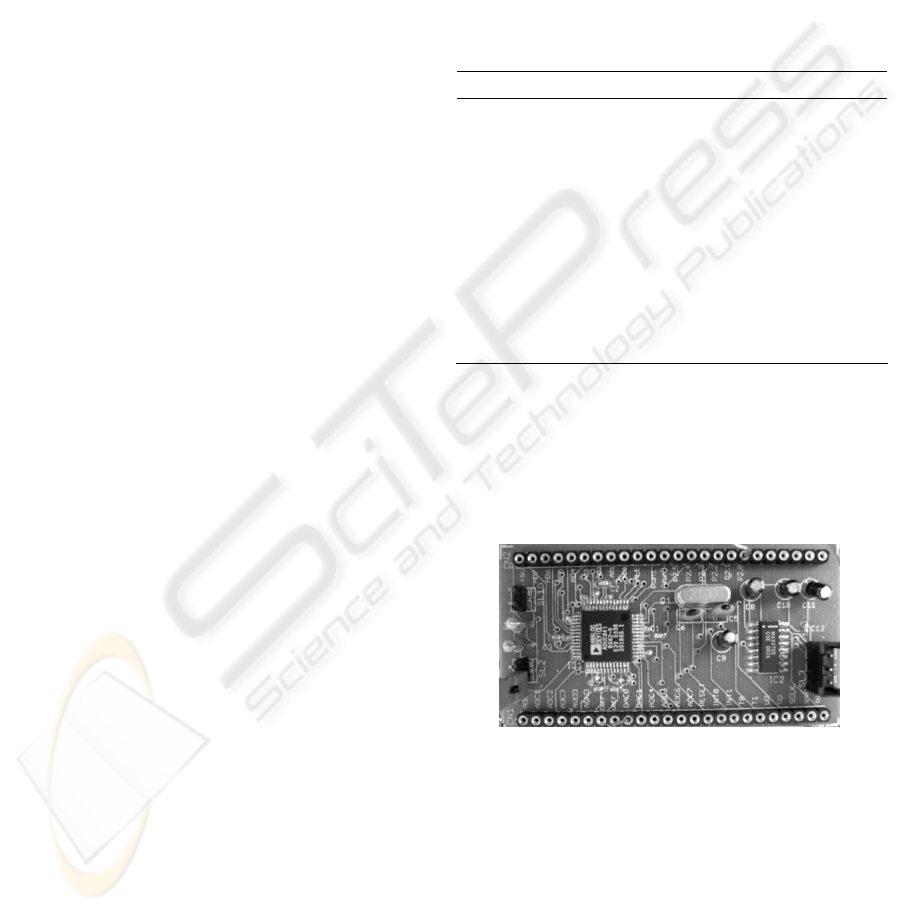
The ADuC841 was welded on the LQFP-to-DIL
adapting board showed in Figure 2, developed to
facilitate the access to the microconverter pins.
Figure 2: Adapter board from LQFP to DIL used in the
prototype, evidencing the ADuC841 µC and the serial
download interface to internal FLASH.
The other prototype components were mounted on a
universal pre-drilled board, and the whole circuit
was conditioned in a plastic box (Phoenix
Mecano/BOPLA), as it can be observed in Figure 3.
SimPac I prototype was exhaustively tested with a
commercial AEP equipment (Contronic, 2007),
presenting all AEP signals with synchronism,
amplitude and timing as expected.
BIODEVICES 2008 - International Conference on Biomedical Electronics and Devices
132
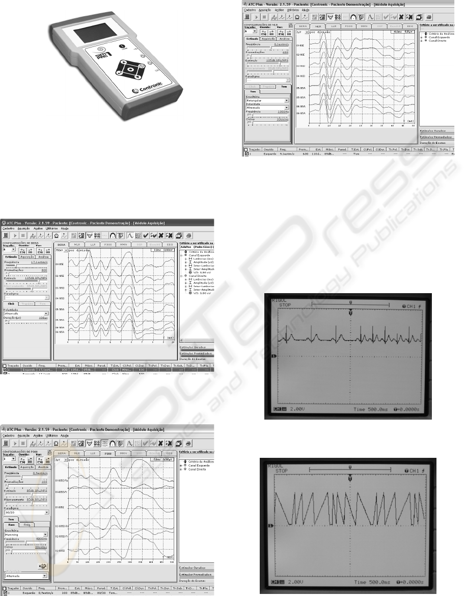
Figure 3: SimPac I layout.
Some of these signals are presented through the
software ATC Plus version 2.1.59 (Contronic,
2007a), and they are shown in Figures 4 through 6.
It is possible to note the perfect repetition of the
AEP signals generated by SimPac I.
Figure 4: Simulated ABR.
Figure 5: Example of simulated rare, frequent and
resulting P300 signals.
Figure 6: Simulated MLR (with VEMP) signal.
In Figures 7 and 8 some ECG and ENG signals from
SimPac I can be seen, which were registered directly
from the DAC outputs with the aid of a Rigol
DS5102MA oscilloscope. These simulated ENG
signals are being used in another project for
validation of automatic algorithms intended to
calculate the slow component of angular velocity of
positional, caloric and rotary nystagmus.
Figure 7: Simulated ECG signal at 60 and 120 BPM.
Figure 8: Simulated ENG at several angular velocities,
clockwise and counter clockwise.
PATIENT SIMULATOR APPLIED TO AUDITORY EVOKED POTENTIALS, ELECTROCARDIOGRAPHY AND
ELECTRONYSTAGMOGRAPHY
133

4 DISCUSSION
SimPac I carried out all the expected basic functions.
Several improvements were made regarding the
previous prototype (SPEA): ECG and ENG signals,
inclusion of performance signals intended to be used
on amplifiers and filters verification (sine and
square), inclusion of optical isolation in the external
trigger input, new user interface using GLCD,
function keyboard and soft starter. A circuit for USB
communication was added to make easy the future
inclusion of new signals to simulate.
For next version we intend to add a white noise
generator to simulate the EEG signal in which the
auditory evoked potential is immersed. That
characteristic will allow extension of the tests of
AEP equipments to the averaging quality.
Some simulators in the market generate
waveforms through complex mathematical formulas,
demanding digital signal processors for its
implementation. SimPac I generates the waveforms
from samples tables by DDS, and the execution can
be made through a simple microconverter. The
SimPac I main advantages are: the generation of
signals that resemble those observed on biological
systems, however with known amplitudes and
latencies; the generation of signals with excellent
repeatability; the substitution of the patient or
volunteer during the development of medical
equipments; and also in development, the
elimination of undesired factors of difficult control,
such as the electrode-skin impedance, other
bioelectric signals like spontaneous EEG or EMG,
and electromagnetic interference.
5 CONCLUSIONS
In this work we demonstrated the viability of
creating an equipment intended to simulate AEPs of
several types, ECG, ENG and performance test
signals. SimPac I simulated signals were verified
through a commercial system for AEP acquisition
and a digital oscilloscope, showing reliability and
precision in the requirements of synchronism,
amplitude, timing and repetition. The use of this
simulator can facilitate the software development
and validation for processing AEP, ECG and ENG,
as well as the hardware adjustment in production,
and the preventive and corrective maintenance of
electro-medical equipments.
ACKNOWLEDGEMENTS
The authors thank to Brazilian Agency CNPq by the
financial support under the grants 507363/2004-3,
310611/2005-9, 120005/2007-7 and 310058/2007-4
(DTI and ITI scholarships) and also to the designer
Leonardo de Jesus Furtado by the SimPac I layout
project.
REFERENCES
Analog Devices, 2003. MicroConverter 12-bit ADCs and
DACs with Embedded High Speed 62-kB Flash MCU.
Analog Devices Inc. Norwood.
Caovilla, H. H., 2000. Audiologia Clínica. Atheneu. São
Paulo.
Castagno, L.A., Tavares, M.C., Richter, C.M. et al., 1994.
Sistema Computadorizado de Eletronistagmografia e
Vectonistagmografia “UCPel/Castagno” (Versão 3.0).
Anais do IV CBIS, pp 26-31.
Chiappa, K. H., 1997. Evoked Potentials in Clinical
Medicine. Third Ed.. Lippincott-Raven Publishers.
Philadelphia.
Contronic, 2007. Manual do Usuário - Módulo de
Aquisição de Sinais Bioelétricos – MASBE – Rev. 4.
Contronic. Pelotas.
Contronic, 2007a. Manual do Usuário - ATC Plus -
Software para Audiometria de Tronco Cerebral –
Build 2.1.X – Rev. 4. Contronic. Pelotas.
Freitas, G.M., Oliveira, T.R, Moraes, R. e Tavares, M.C.,
2006. Simulador de Potenciais Evocados Auditivos de
Curta, Média e Longa Latência Baseado em
Microconversor. Anais do CBEB 2006, v 1, pp 1224-
1227.
Grover, D.; Deller, J. R.; 1999. Digital Signal Processing
and the Microcontroller. Motorola University
Press/Prentice Hall PTR. New Jersey.
Katz, J., 1999. Tratado de Audiologia Clínica, Ed. 4.
Manole. São Paulo.
Prutchi, D., Norris, M., 2005. Design and Development of
Medical Electronic Instrumentation. Wiley. New
Jersey.
Wickenhäeuser, 2005. uC/51 V1.20.04 User´s Manual.
Wickenhäeuser Elektrotechnik. Karlsruche.
BIODEVICES 2008 - International Conference on Biomedical Electronics and Devices
134
