
AUGMENTED COMANIPULATION IN ROBOTIC SURGERY
B. Cagneau, D. Bellot, G. Morel,
Institut des Syst`emes Intelligents et Robotique, 18 route du Panorama, 92265 Fontenay Aux Roses, France
N. Zemiti
TIMC-IMAG Laboratory, 38706 La Tronche Cedex France
G. D’Agostino
Universit`a Federico II di Napoli, Facolt`a di Ingegneria dell’Automazione, Corso Umberto I, 80138 Napoli, Italy
Keywords:
Force control, robotic surgery, cobotic, augmented comanipulation.
Abstract:
This paper presents a control scheme for augmented comanipulation with force feedback in robotic surgery.
This approach aims at increasing the surgeon’s dexterity. The surgeon manipulates a handle mounted on the
robot which manipulates the instrument. The control law ensures that the instrument applies on the organ
the same forces that the surgeon applies on the handle but decreased by a scale factor. As a consequence,
the robotic device provides the surgeon with an augmented sensation of the interaction forces between the
instrument and the organ. The proposed control law does not require any knowledge of the environment. This
control scheme is proven stable thanks to a passivity study. Indeed, passivity analysis is a useful tool for the
stability analysis of a robot interacting with an unknown environment. Experimental results are presented on
a robot dedicated to minimally invasive surgery.
1 INTRODUCTION
In the context of robotic surgery, the surgeon and the
medical staff have to interact with the robot. Depend-
ing on the surgical task, the degree of cooperation can
be really different. Simple tasks may be realized by
the robot, in an autonomous way, under the surgeon’s
supervision. For example, the surgeon defines the de-
sired positions via an interface and the robot moves
to these positions. However more complex tasks re-
quire the surgeon’sjudgment and, thus, cannot be per-
formed autonomously by the robot. These tasks re-
quire that the robot works in cooperation with the sur-
geon. The surgeon’s skills are thus improved as the
robot increases his dexterity. To do so, one of the
possibilities is robot’s force control. For instance, in
minimally invasive surgery, a robotic device could be
used in order to display manipulation forces back to
the surgeon. Indeed, since the instruments are manip-
ulated through a trocar and because of the friction in
the trocar, the surgeon looses the sensation of the in-
teraction forces between the instrument and the organ
and his dexterity is thus reduced. An other applica-
tion of force control that could increase the dexterity
of the surgeon is force scaling. Indeed, for precise
manipulation tasks, a robotic device could provide the
surgeon with an augmented sensation of the interac-
tion forces between the instrument and the organ.
Comanipulation appears to be a good solution to over-
come these problems. Comanipulation is a direct in-
teraction between the surgeon and the robot: the in-
strument is manipulated simultaneously by the sur-
geon and by the robot. The main difference between
comanipulation and teleoperation is that no master
arm is needed to impose displacements to the robot.
So the complexity and the cost of a comanipulation
system may be lower since it involves only one me-
chanical system. Moreover, the use of a comanipu-
lation system may be more intuitive for the human
operator.
Different approaches have been studied concerning
the comanipulation. Some systems are able to impose
virtual constraints to the surgeon’s gesture which re-
strain the tool into a delimited area of the task-space
47
Cagneau B., Bellot D., Morel G., Zemiti N. and D’Agostino G. (2008).
AUGMENTED COMANIPULATION IN ROBOTIC SURGERY.
In Proceedings of the First International Conference on Biomedical Electronics and Devices, pages 47-54
DOI: 10.5220/0001053600470054
Copyright
c
SciTePress

and forbid the access to critical zones.
For example, in (Schneider et al., 2000), the sys-
tem PADyC has been presented. The clinical results
obtained with this system concern pericardial punc-
ture. It consists to remove pathological liquid from
the pericardium using a needle. PADyC can be used
under different control modes corresponding to the
degree of autonomy the surgeon wants. The robot is
controlled with a velocity loop and it imposes con-
straints on the surgeon to prevent damages on the sur-
face of the heart. These constraints are computed with
respect to the relative position between the needle and
the percutaneous access. Indeed, a model of the op-
eration’s area is created during a pre-operative phase.
This model is then used to derive the constraints field.
Here no force control is used to perform the operation.
In (Jakopec et al., 2003), the Acrobot system is
used to assist the surgeon during an operation of knee
replacement. The main feature of this system is to im-
pose virtual constraints on the surgeon when he/she
cooperates with the robot. When the task has been
defined with the planning software, the manipulator
is able to move freely the robot to the operations area.
If the surgeon moves the tool outside the defined path,
the robot applies forces on the user to modify the cur-
rent trajectory. It has been clinically proven that the
preparation of bones surfaces are more accurate com-
paring to a classical operation. Once again, no force
control is performed with this system.
Moreover, some systems can exploit a measure of
forces. Therefore, there is no need to use models of
contacts to obtain the measure of distal forces. It is
also possible to derive constraints which are directly
based on the forces applied by the surgeon on the or-
gans.
In (Kazanzides et al., 1992), a force controller is used
so that the surgeon can guide the robot. The surgi-
cal tool is attached below a force sensor mounted on
the robot’s wrist. The force controller uses the mea-
sured forces to provide the reference to an inner ve-
locity control loop. When the desired force is null,
any applied force on the instrument causes the robot
to move in the direction of this force. So, the surgeon
can guide the robot by holding the tool.
In the same manner, the Surgicobot system
(Kochan, 2004) allows the surgeon and the robot to
manipulate the same drilling instrument for maxillo-
facial interventions. The surgeon can freely move the
instrument except in some predefined space where the
robot generates restrictive forces in order to prevent
the surgeon from moving the instrument too close to
vital nerves.
In (Taylor et al., 1999), (Kumar et al., 2000)
and (Roy et al., 2002) augmented comanipulation ap-
proaches are presented: the surgeon holds a handle
mounted on the robot and the robot manipulates the
instrument in a way such as it exerts on the organ the
same force that the surgeon applies on the handle, but
scaled-down. Three different control laws using an
inner position/velocity control loop are compared in
(Roy et al., 2002). The best results are obtained with
an adaptive control law involving the estimation of
the environment’s compliance. However, when the
contact with the environment is lost, the estimation
becomes problematic. Another disadvantage of this
control law is that it requires differentiation of the
force applied by the surgeon on the handle which is
a noisy signal.
Even if benefits presented in the above references are
important (e.g. gesture’s accuracy or the increase of
system’s safety), none of these systems allow the sur-
geon to feel an amplified version of the distal forces
acting between the tool and the organ.
In this paper, we present a control scheme for aug-
mented comanipulation with force feedback. The
main advantages of this control law is that it does not
require any knowledge of the environment nor differ-
entiation of a noisy signal. This approach is an exten-
sion of previous works (Zemiti et al., 2006) realized
in our laboratory.
The first part of this paper is devoted to the proposed
control law for augmented comanipulation. This con-
trol scheme is proven stable thanks to a passivity
study in the second part. Experimental results with
a robot dedicated to minimally invasive surgery are
presented in the last part.
2 AUGMENTED
COMANIPULATION
2.1 Principle of the Approach
We present, hereafter, a robotic device in order to as-
sist the surgeon for accurate manipulation tasks re-
quiring human judgment and involving small interac-
tion forces between the surgical tool and the organ.
Therefore, the proposed device allows an augmented
comanipulation. It is a comanipulation system be-
cause the surgical instrument is held simultaneously
both by the surgeon and by the robot. We call it aug-
mented because the robot is controlled in such a way
that the surgeon is provided with an amplified sensa-
tion of the interaction forces between the instrument
and the organ. As a consequence, the instrument ap-
plies on the organ the same forces that the surgeon
would apply in a transparent mode but decreased by a
BIODEVICES 2008 - International Conference on Biomedical Electronics and Devices
48
scale factor. This device can also filter the surgeon’s
tremor in order to increase the accuracy of the task.
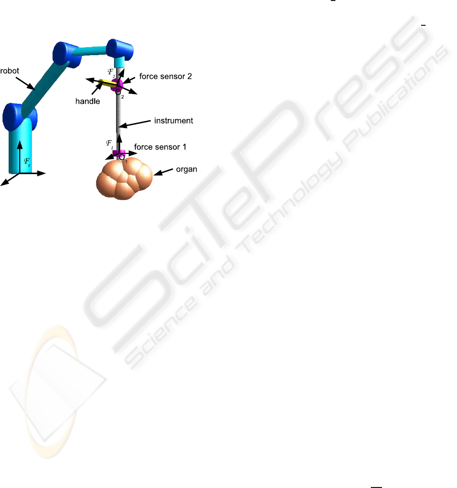
This approach supposes that the reference forces pro-
vided by the surgeon and the interaction forces be-
tween the instrument and the organ may be measured
separately. Therefore a handle equipped with a force
sensor (force sensor 2) is mounted on the instrument
(see figure 1). The surgeon manipulates this handle
and the force sensor 2 measures the forces applied
by the surgeon on the instrument at point O
2
. The
force sensor 1 measures the forces applied by the or-
gan on the instrument at point O
1
. The data provided
Figure 1: Setup for augmented comanipulation.
by the force sensor number i are wrenches applied
on point O
i
and expressed in the basis of frame F
i
linked to the sensor. In order to be compared these
wrenches have to be expressed in the same point and
in the same basis. As the transformations between the
basis linked to frames F
i
and the basis linked to the
fixed robot base frame F
r
are supposed to be known,
we choose to express the wrenches in the basis linked
to the frame F
r
. So, from the data provided by the
force sensor 1, we can compute −w
e
the wrench ap-
plied by the organ on the instrument at point O
1
and
expressed in frame F
r
. From the data provided by the
force sensor 2, we can compute −w
s
the wrench ap-
plied by the surgeon on the instrument at point O
2
and
expressed in frame F
r
. Note that w
e
and w
s
are respec-
tively the wrench applied by the instrument on the or-
gan at point O
1
and the wrench applied by the instru-
ment on the surgeon at point O
2
. Assuming that the
transformation between the frame F
1
and the frame
F
2
is known, we can compute the wrench −w
u
ap-
plied by the surgeon on the instrument at point O
1
in
F
r
: −w
u
= T
12
(−w
s
) with
T
12
=
I
3
0
3
−[O
2
O
1
]
×
I
3
where [O
2
O
1
]
×
denotes the skew symmetric matrix
associated with the vector from O
2
to O
1
expressed
in the basis of frame F
r
. However, in future work,
it will be interesting to compute this transformation
with a calibration process. In the Section 4, we as-
sume that the mechanical design is precise enough to
have a good estimation of this transformation.
With these notations, as detailed in subsection 2.3,
the aim of the proposed approach is to control the
robot such that w
u
= −
1
β
w
e
where β ∈]0;1] i.e. the
surgeon feels the forces applied by the organ on the
instrument, −w
e
, amplified by a scale factor
1
β
> 1.
The proposed control scheme is presented in the fol-
lowing subsection.
2.2 Proposed Control Scheme
The robot dynamics is modeled by the general form:
M(q) ¨q+C(q, ˙q) ˙q+ Γ
v
˙q+ G
g
(q) = τ − τ
e
− τ
u
(1)
where q ∈ R
n
denotes the joint positions, M(q) is the
positive definite symmetric inertia matrix, C(q, ˙q) ˙q is
a vector grouping the Coriolis and centrifugal joint
torques, Γ
v
˙q is a vector grouping the dissipative joint
torques, G
g
(q) is a vector grouping the gravity joint
torques, τ is the command vector for joint torques.
−τ
e
and −τ
u
are the joint torques corresponding re-
spectively to −w
e
and −w
u
i.e. −τ
e
= J
t
(q)(−w
e
)
and −τ
u
= J
t
(q)(−w
u
) where J(q) is the Jacobian
matrix of the robot at point O
1
, expressed in the basis
of F
r
.
At the lowest level of the controller, a proportionalve-
locity feedback is used in order to partially linearize
the robot dynamics:
τ = −B˙q+
c
G
g
(q) +
b
C(q, ˙q) ˙q+ τ
c
(2)
where B is a symmetric positive definite matrix of
feedback gains, τ
c
is the new command vector for the
joint torques,
c
G
g
(q) and
b
C(q, ˙q) ˙q are estimated val-
ues of G
g
(q) and C(q, ˙q) ˙q. Therefore, the model (1)
becomes:
M(q) ¨q+ B˙q = τ
c
− τ
e
− τ
u
(3)
The proposed control scheme is presented on fig-
ure 2.
In this figure the Jacobian matrix J(q) is noted J.
This control scheme introduces notations defined as
follow:
• C
τ
(s) is a Proportional-Integral torque compen-
sator at the joint level such that:
C
τ
(s) = K
p
+
K
i
s
(4)
where K
p
∈ R
n×n
and K
i
∈ R
n×n
are symmetric,
positive definite matrices.
AUGMENTED COMANIPULATION IN ROBOTIC SURGERY
49

Figure 2: Augmented Comanipulation force control scheme
in joint space.
•
˙
X is the 6-component vector grouping the coordi-
nates of the rotational and linear velocity of the
instrument at point O
1
with respect to frame F
r
,
expressed in the basis of F
r
.
In the sequel the following assumption will be
used :
Assumption 1 The matrix J(q) is of full rank n
This assumption means that the robot is not in a sin-
gular configuration.
2.3 Equilibrium
The stability of the control scheme 2 will be proved in
the following section. So, assuming that this control
scheme is stable, as the controller C
τ
(s) involves an
integral term, the torque error ε
τ
will be null at the
equilibrium. So, at the equilibrium:
τ
d
− τ
e
= 0 (5)
As the stable low-pass filter G(s) has a steady-state
gain equal to 1, at the equilibrium, τ
d
= J(q)
t
β(−w
u
).
Thus (5) leads to :
J(q)
t
(−w
u
) +
1
β
(−w
e
)
= 0 (6)
If n = 6 i.e. if we consider a 6 joints robot, the matrix
J(q) is square. Moreover, according to assumption
(1), this matrix is of full rank. Therefore, it can be
deduced from equation (6) that:
w
u
=
1
β
(−w
e
) (7)
Suppose that we choose β = 1. Then, equation (7) can
be written:
w
u
= (−w
e
) (8)
It means the wrench w
s
sensed by the surgeon at
point O
2
is such that its expression at point O
1
, w
u
, is
equal to the wrench −w
e
applied by the organ on the
instrument expressed at point O
1
. Thus the surgeon
manipulates the instrument in a transparent way i.e.
the surgeon senses the wrench w
s
as if he/she were
manipulating a zero mass instrument without any
friction.
Similarly, if β ∈]0;1[, equation (7) means that the
wrench w
s
sensed by the surgeon is an amplified
version, by the scale factor
1
β
> 1, of the wrench
that he would sense in a transparent manipulation.
Let’s remark that (7) can be written w
e
= β(−w
u
). It
means that the wrench applied by the instrument on
the organ at point O
1
is the wrench applied by the
surgeon at the same point, reduced by the scale factor
β.
If n < 6, J
t
(q) ∈ R
n×6
is not square. Thus it
cannot be deduced from (6) that the wrench error
ε
w
= (−w
u
) +
1
β
(−w
e
) is zero. The wrench error ε
w
is not necessarily zero but belongs to the null space
of J
t
(q). An equilibrium is obtained between w
u
and
1
β
(−w
e
).
3 PASSIVITY
In the proposed approach, the robot interacts with its
environment. The stability of the control loop de-
pends not only on the robot dynamics but also on the
environment dynamics. However we cannot assume
for a known model for the environment. Therefore,
a useful tool for the stability analysis of the proposed
control loop is passivity analysis since this study does
not require any environments model. Thus, whatever
could be the contacts (robot-organ / robot-surgeon),
the passivity analysis ensures that the system remains
stable. The principle of a passivity study is presented
in the following subsection
3.1 Principle
Let consider an LTI system with an input u, an out-
put y, such that y = T(s)u with T(s) a real rational
transfer matrix. This system is passive if and only
if T(s) is positive real. In turn, positive realness can
be checked by the following property (Anderson and
Vongpanitlerd, 1973):
Property 1 Let s
k
= σ
k
+ jω
k
, k ∈ {1..m}, denote the
m poles of all the elements T
ij
(s) of T(s), and let jω
l
,
l ∈ {1..p}, denote the p ≤ m pure imaginary poles of
all the elements T
ij
(s) of T(s). The transfer T(s) is
Positive Real if, and only if:
1. ∀k ∈ {1..m},σ
k
< 0 ;
2. ∀l ∈ {1..p}, jω
l
is of multiplicity 1, and the as-
sociated residue matrix K
l
is hermitian, positive
BIODEVICES 2008 - International Conference on Biomedical Electronics and Devices
50

semidefinite (PSD). The matrix K
l
can be com-
puted as:
K
l
= lim
s→ jω
l
(s− jω
l
)T(s) , if ω
l
is finite
and: K
l
= lim
s→∞
T(s)
s
, if ω
l
is infinite
Note that a zero of T
ij
(s) is considered as a pole
at the infinity.
3. T
t
(− jω) + T( jω) = T
∗
( jω) + T( jω) is PSD, for
any ω ∈ R − {ω
l
,l ∈ {1..p}}.
Let, now, consider an LTI system with two dif-
ferent inputs u
1
and u
2
provided by two different en-
vironments, and assume that this system is described
by: y = T
1
(s)u
1
+ T
2
(s)u
2
. This system is passive if
and only if T
1
(s) is positive real and T
2
(s) is positive
real.
3.2 Passivity of the Modified Force
Control Scheme
3.2.1 Modeling, Linearized Robot Dynamics
The robot controlled by the control scheme depicted
on figure 2 is a system whose output is
˙
X. This sys-
tem has two inputs −w
u
and −w
e
provided by two
different environments, respectively the surgeon and
the organ. So, in order to study the passivity of this
system we first have to compute the transfer matrix
Y
u
(s) between −w
u
and
˙
X and the transfer matrix
Y
e
(s) between −w
e
and
˙
X. This computation sup-
poses that the system is linear. Therefore, in order to
study the passivity of the proposed control scheme,
we linearize the robot dynamics (3) by assuming that
the robot evolves in a neighborhood of a given joint
configuration q
0
so that we can set M = M(q
0
) con-
stant. The resulting linearized model writes:
˙q = Y
r
(s)(τ
c
− τ
u
− τ
e
) with Y
r
(s) = (Ms+ B)
−1
(9)
where s is the Laplace complex variable. More-
over, under the assumption that the robot evolves in
a neighborhood of a given joint configuration q
0
, we
can set J = J(q
0
) constant. Then, we get the follow-
ing model:
˙
X = Y
u
(s)(−w
u
) + Y
e
(s)(−w
e
) (10)
where:
Y
u
(s) = JY
r
(s) [I
n
+ β(C
τ
(s) + I
n
)]J
t
Y
e
(s) = JY
r
(s) [I
n
+ C
τ
(s)]J
t
3.2.2 Passivity Study
The system (10) is passive if and only if the matrices
Y
u
(s) and Y
e
(s) are positive real. As J is supposed
to be of full rank (Assumption 1), this condition is
equivalent to the positive realness of the matrices Y
u,2
and Y
e,2
defined as follow:
Y
u,2
= Y
r
(s) [I
n
+ β(C
τ
(s) + I
n
)]
Y
e,2
= Y
r
(s)[I
n
+ C
τ
(s)]
(11)
Equations (11), (9), and (4) lead to :
Y
u,2
= (Ms+ B)
−1
h
I
n
+ βK
′
p
+
βK
i
s
i
Y
e,2
= (Ms+ B)
−1
h
I
n
+ K
p
+
K
i
s
i
(12)
where K
′
p
= K
p
+ I
n
.
We first derive conditions ensuring the positive re-
alness of Y
u,2
(s). The poles of Y
u,2
(s) are s
1
= 0 and
the poles of Y
r
(s). The poles associated to Y
r
(s) are
the solutions of det(Ms+ B) = 0 i.e. the eigenvalues
of −M
−1
B. As far as M and B are symmetric posi-
tive definite matrices, the eigenvalues of −M
−1
B are
negative real.
In order to check the second condition of property
1, we compute the residue K
1
associated to pole s
1
=
0. We get:
K
1
= lim
s→s
1
sY
u,2
= βB
−1
K
i
As β > 0, we deduce the following condition for the
passivity of the control scheme:
B
−1
K
i
≥ 0 (13)
The third condition of property 1 consists in
checking, for any ω ∈ R − {0}, the positive semidefi-
niteness of the matrixH
1
( jω) defined as follow:
H
1
( jω) = Y
u,2
( jω) + Y
u,2
t
(− jω)
= ( jωM+ B)
−1
h
I
n
+ βK
′
p
+
βK
i
jω
i
+
h
I
n
+ βK
′
p
+
βK
i
− jω
i
(− jωM+ B)
−1
(14)
because K
′
p
, K
i
, M and B are symmetric.
Positive semidefiniteness of H
1
( jω) is equivalent
to positive semidefiniteness of H
2
( jω) defined as fol-
low:
H
2
( jω) =
1
β
( jωM+ B)H
1
( jω)(− jωM+ B)
=
h
1
β
I
n
+ K
′
p
+
K
i
jω
i
(− jωM+ B)
+( jωM+ B)
h
1
β
I
n
+ K
′
p
+
K
i
− jω
i
(15)
We get:
H
2
( jω) = R
1
+ R
2
+ jωIm
1
+
j
ω
Im
2
(16)
AUGMENTED COMANIPULATION IN ROBOTIC SURGERY
51
where:
R
1
= (2/β)B
R
2
= K
′
p
B+ BK
′
p
− (K
i
M+ MK
i
)
Im
1
= MK
′
p
− K
′
p
M
Im
2
= K
i
B− BK
i
The hermitian matrix H
2
( jω) must be PSD in order
to ensure passivity. Thus its real part has to be PSD
and its imaginary part has to be null. Therefore, the
following conditions have to be satisfied for any ω ∈
R − {0}:
R
1
+ R
2
≥ 0 (17)
ωIm
1
+
1
ω
Im
2
= 0 (18)
Thus, condition (18) is equivalent to:
R
1
+ R
2
≥ 0
Im
1
= 0
Im
2
= 0
(19)
To summarize, the matrix Y
u,2
(s) and thus Y
u
(s)
is positive real if and only if the following conditions
are satisfied:
B
−1
K
i
≥ 0
Im
1
= 0
Im
2
= 0
R
1
+ R
2
≥ 0
(20)
As far as positive realness of Y
e,2
(s) is concerned,
with a similar reasoning we deduce that the first and
the second condition of property 1 are satisfied if and
only if M
−1
B > 0 and B
−1
K
i
≥ 0. It can be noticed
in equations (12) that the expression of Y
e,2
(s) is sim-
ilar to the expression of Y
u,2
(s) when β = 1 and K
′
p
is replaced by K
p
. Therefore, we deduce from equa-
tions (19) and (17) that the third condition ensuring
the positive realness of Y
e,2
(s) is satisfied if and only
if:
MK
p
− K
p
M = 0
K
i
B− BK
i
= 0
B+ K
p
B− K
i
M ≥ 0
(21)
The equations (20) and (21) lead to the following
conditions for the passivity of the proposed control
scheme:
B
−1
K
i
≥ 0
MK
p
− K
p
M = 0
K
i
B− BK
i
= 0
(
1
β
I
n
+ K
′
p
)B− K
i
M ≥ 0
(22)
with K
′
p
= K
p
+ I
n
.
4 EXPERIMENTS
The aim of these experiments is to show that it is pos-
sible to provide force feedback to the surgeon thanks
to proposed control scheme. Furthermore, for differ-
ent values of the gain β, we will verify that the sys-
tem remains stable. Experimentalsetup will be briefly
described and benefits of augmented comanipulation
will be evaluated experimentally.
Note that, in the rest of the paper, the used joint torque
compensator gains and the values of B and β were
chosen in such a way that the conditions given in 22
are verified.
4.1 Experimental Setup
The robot MC
2
E (French acronym for compact ma-
nipulator for endoscopic surgery) is a Kinematically
Defective Manipulator (KDM) which means that it
has fewer joints than the dimension of the space
in which its end-effector evolves. It is specially
suited for minimally invasive robotic surgery appli-
cations(Zemiti et al., 2007). With n = 4 joints and a
spherical structure, this robot provides 4 degrees of
freedom (DOFs) at the instrument tip.
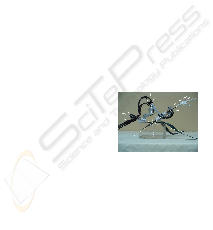
The Figure 3 shows how the mechanical constraint
Θ
1
Θ
2
Θ
3
d
4
Figure 3: MC
2
E can comanipulate an instrument with a sur-
geon, and measures wrenches that are applied either by the
surgeon, or at the instrument tip.
is created. The lower part of the robot is dedicated to
the orientation of the instruments. The upper part al-
lows translation and rotation of the instrument along
its own axis.
Since the 4 axis coincide, there is a fulcrum point
which allows the insertion of the trocar into the pa-
tient’s body. This mechanical structure is clearly
adapted to Mini Invasive Surgery. Traumatisms are
reduced because translations through the fulcrum
point are not allowed.
Apart from its compactness, the main feature of
this robot is that it offers a possibility for force
BIODEVICES 2008 - International Conference on Biomedical Electronics and Devices
52
measurement in MIS. Namely, MC
2
E can measure
the distal organ-instrument interaction with a 6-axis
force-torque sensor placed outside the patient. Thus,
it is subject to much less sterilization constraints. Re-
markably, due to the special mounting of the force
sensor, these measurements are not affected by the
disturbance forces and torques arising from the inter-
action between the trocar and the instrument.
It is important to mention that the control scheme that
we have detailed in Section 2 can be used in other
fields of interest and not only in laparoscopic surgery.
For example, it is possible to improve surgeon accu-
racy during otologic surgery. The forces applied dur-
ing such kinds of interventions are very low. There-
fore, it should be useful to provide an amplified ver-
sion of these forces thanks to force feedback.
The new control scheme presented in section 2 indi-
cates that the robot interacts with two different envi-
ronments (the organ and the surgeon). This configu-
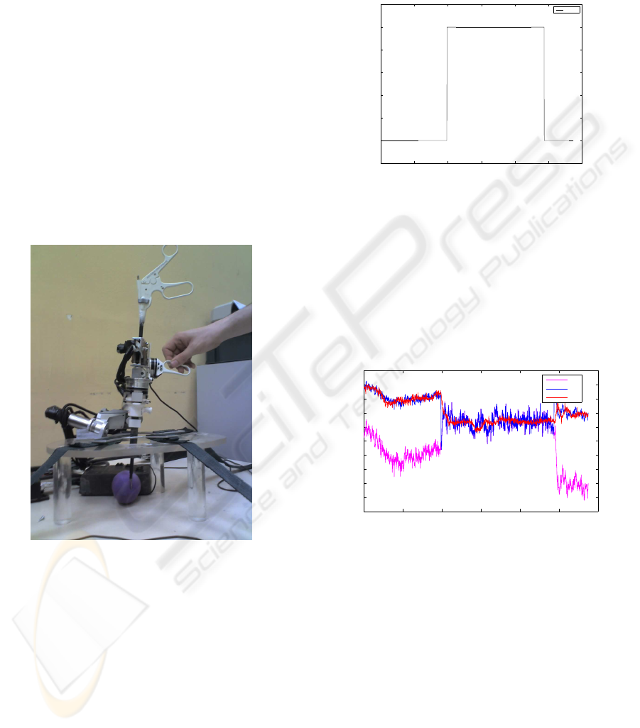
Figure 4: Experimental Setup.
ration is shown on figure 4. It needs a second force
sensor to measure forces between the robot and the
surgeon. Therefore to measure forces applied by the
surgeon, a second force sensor has been added on the
robot. Due to difficulties to fix it directly on the han-
dle, it has been deported on the second axis of MC
2
E.
This particular disposition was the quickest way to
provide force feedback to the manipulator. However,
the same disposition is not adapted to transmit forces
along instrument’s axis. In order to overcome this
problem, next step will be to modify existing experi-
mental setup to exploit each of the robot’s DOF.
4.2 Experimental Results
The figure 5 shows how the gain β has been modi-
fied during the experiment. β = 1 is a particular value
0 2 4 6 8 10 12
0.4
0.5
0.6
0.7
0.8
0.9
1
1.1
Time (s)
Gain values
Value
Figure 5: Gain values vs. time.
for which torques measured on the organ are equal
to torques applied by the manipulator. When setting
β = 0.5, torques applied on the organ should be de-
creased by a factor 2.
The figure 6 depicts torque measurements. It allows
to compare torques applied on the organ, torques pro-
vided to the controller and torques applied on the ma-
nipulator. This result demonstrates that the proposed
0 2 4 6 8 10 12
−0.6
−0.55
−0.5
−0.45
−0.4
−0.35
−0.3
−0.25
−0.2
−0.15
−0.1
Time (s)
Torques (N.m)
τ
u
τ
d
τ
e
Figure 6: Torque values vs. time.
control scheme allows a reduction of the torques ap-
plied on the organ. At t = 10s, β is switched from 1.0
to 0.5. One can notify that torques applied on the or-
gan almost remain the same but torques applied by the
surgeon are amplified. Therefore, to apply the same
efforts on the organ, the surgeon must amplify forces
acting on the robot. This result satisfies equation (7).
The figure 7 shows that the system remains stable
for different values of gains. Furthermore, it demon-
strates that good performances can be achieved with
the controller which has been proposed in section 2.
Error appearing on Figure 7 is mainly due to noise
on measurement. However, one can notice that there
are some error peaks on this plot. This phenomenon
is due to the modification of the force feedback gain
AUGMENTED COMANIPULATION IN ROBOTIC SURGERY
53

0 2 4 6 8 10 12
−0.2
−0.15
−0.1
−0.05
0
0.05
0.1
0.15
Time (s)
Torque (N.m)
Error
Figure 7: Torque error vs. time.
during experiments. In practice, if a fixed value of β
is used, these peaks would not appear.
5 CONCLUSIONS
This paper presents a modified version of a force con-
trol scheme. In the context of comanipulation, it is
possible to provide force feedback to the manipula-
tor by modifying torques reference. In order to obtain
such results, a second force sensor is necessary to dis-
tinguish manipulator and environment forces.
Robots kinematic has been used to deal with
torques equilibrium. In other words, using a gains
matrix allows reduction of forces acting on the envi-
ronment and amplification of forces acting on the ma-
nipulator. Experiments have been conducted to show
efficiency of the proposed control scheme.
Moreover, a formal proof of passivity has been es-
tablished. It ensures stability of the system whatever
could be contacts between the robot and its environ-
ment.
In future work, in-vivo experiments will be con-
duced. Even if experiments are satisfying with actual
experimental setup, it should be modified to exploit
the last 2 DOFS. A new handle seems to be the easi-
est way to use existing robot.
ACKNOWLEDGEMENTS
Barth´elemy Cagneau would like to acknowledge
Clara Lord for her contribution to this work. Scien-
tific and technical discussions have been very useful
to improve the quality of this paper.
REFERENCES
Anderson, B. D. and Vongpanitlerd, S. (1973). Network
Analysis and Synthesis -A Modern Systems Theory
Approach-. Englewood Cliffs, N.J. , Prentice-Hall.
Jakopec, M., Baena, F., Harris, S., Gomes, P., Cobb, J., and
Davies, B. (2003). The hands-on orthopaedic robot
acrobot: Early clinical trials of total knee replacement
surgery. IEEE Transactions on Robotics and Automa-
tion, 19(5):902–911.
Kazanzides, P., Zuhars, J., Mittelstadt, B., and Taylor, R. H.
(1992). Force sensing and control for a surgical robot.
In Proceedings of the IEEE International Conference
on Robotics and Automation, pages 612–617.
Kochan, A. (2004). A cobotic solution for surgical appli-
cations. Industrial Robot: An International Journal,
31:478–480.
Kumar, R., Berkelman, P., Gupta, P., Barnes, A., Jensen,
P. S., Whitcomb, L. L., and Taylor, R. H. (2000).
Preliminary experiments in cooperative human/robot
force control for robot assisted microsurgical manipu-
lation. In Proceedings of the IEEE International Con-
ference on Robotics and Automation, pages 610–617.
Roy, J., Rothbaum, D. L., and Whitcomb, L. L. (2002).
Haptic feedback augmentation through position based
adaptive force scaling: theory and experiment. In Pro-
ceedings of the IEEE/RSJ International Conference on
Intelligent Robots and Systems, pages 2911–2919.
Schneider, O., Troccaz, J., Chavanon, O., and Blin, D.
(2000). Padyc: a synergistic robot for cardiac punctur-
ing. In Proceedings of the IEEE International Confer-
ence on Robotics and Automation, pages 2883–2888.
Taylor, R., Jensen, P., Whitcomb, L., Barnes, A., Kumar, R.,
Stoianovici, D., Gupta, P., Wang, Z., deJuan, E., and
Kavoussi, L. (1999). A steady-hand robotic system for
microsurgical augmentation. International journal of
robotics research, 18:1201–1210.
Zemiti, N., Morel, G., Micaelli, A., Cagneau, B., and Bel-
lot, D. (2006). A passive formulation of force con-
trol for kinematically constrained manipulators. In
Proceedings of the IEEE International Conference on
Robotics and Automation, pages 2238–2243.
Zemiti, N., Morel, G., Ortmaier, T., and Bonnet, N. (2007).
Mechatronic design of a new robot for force control in
minimally invasive surgery. IEEE/ASME Transactions
on Mechatronics, 12(2):143–153.
BIODEVICES 2008 - International Conference on Biomedical Electronics and Devices
54
