
OPTIMIZATION OF A FES CYCLING NEUROPROSTHESIS ON
STROKE PATIENTS BY MEANS OF THE LEFT AND RIGHT
CRANK MEASUREMENTS
Ferrante Simona
1
, Comolli Lorenzo
2
, Pedrocchi Alessandra
1
, Bocciolone Marco
2
, Ferrigno Giancarlo
1
and Molteni Franco
3
1
Bioengineering Department, NITLab - TBMLab, Politecnico di Milano, Via Garofalo 39, Milano, Italy
2
Department of Mechanical Engineering, Politecnico di Milano, Via La Masa 34, Milano, Italy
3
Valduce Hospital, Villa Beretta Rehabilitation Center, Via N.Sauro 17, Costamasnaga (LC), Italy
Keywords: FES cycling, rehabilitation, hemiplegia.
Abstract: The use of functional electrical stimulation (FES) is a well established method in the rehabilitation of stroke
patients. In particular, a bilateral movement such as cycling induced by FES would be crucial for these
patients who had an unilateral motor impairment and had to recover an equivalent use of the limbs. To
improve the rehabilitative effects of the FES cycling, a metrologically qualified cycle-ergometer was used,
so that the left and right crank torque values are measured in real-time. Three protocols were evaluated.
First, healthy subjects performed voluntary pedaling. Second, healthy subjects were stimulated one muscle
individually to study the contribution of each single muscle to the cycling. Third, stroke patients executed a
complete FES cycling trials. Results demonstrated that the proposed sensors could be successfully used to
monitor online the unbalance of the cycling. Single muscle tests showed that only the quadriceps and the
hamstrings provided a significant contribution to the crank torque. Patient trials confirmed the difficulty for
stroke subjects to carry out symmetrical cycling. The use of the proposed sensors, hence, could offer a good
signal for biofeedback neuroprostheses and for closed loop controllers.
1 INTRODUCTION
A neuroprosthesis is defined as a functional
electrical stimulation (FES) device used as a
substitute for lost neurological function. The use of a
neuroprosthesis is a well established method in the
rehabilitation of individuals with spinal cord injuries
and stroke (Kralj, Acimović & Stanic, 1993,
Petrofsky, 2004). Among all the existent
neuroprostheses, the cycling movement induced by
the stimulation of the major muscles of the lower
limbs is now becoming a spread application (Hunt et
al., 2004, Trumbower, & Faghri 2005, Szecsi et al.,
2007). In the following this artificial movement will
be named FES cycling.
One of the most difficult and appealing
improvements in FES research is the integration of
hardware and software and the development of
control systems for the neuroprosthesis in order to
enhance the clinical benefits for the patients. Some
of the rehabilitation objectives for spinal cord
injured patients are an increase in muscular tone, an
improvement in the peripheral and cardiac
circulation avoiding the occurrence of decubitus
ulcera and the prevention of joint rigidity (Hunt et
al. 2004). In stroke patients, the neuroprosthesis also
becomes therapeutic and in fact, it permits one to
learn new motor strategies for Central Nervous
System (CNS), exploiting residual capacity (Lee &
van Donkelaar, 1995, Sheffler & Chae, 2007).
Indeed, FES cycling providing the complete
afference of the task to the stroke patients could re-
educate the synaptic controls needed to produce a
well organized movement. Because of the laterality
of the pathology, one of the rehabilitation aims is the
recovery of walking and particularly the recovery of
the symmetry of the movement. Therefore, the use
of FES cycling was investigated as a method to
re-learn the bilateral and symmetrical use of the legs.
206
Simona F., Lorenzo C., Alessandra P., Marco B., Giancarlo F. and Franco M. (2008).
OPTIMIZATION OF A FES CYCLING NEUROPROSTHESIS ON STROKE PATIENTS BY MEANS OF THE LEFT AND RIGHT CRANK MEASURE-
MENTS.
In Proceedings of the First International Conference on Biomedical Electronics and Devices, pages 206-211
DOI: 10.5220/0001054202060211
Copyright
c
SciTePress
The feasibility of applying FES cycling to stroke
patients was analyzed in a previous study and
encouraging results were reached (Ferrante et al.,
2006). The stimulation strategy delivered to the
quadriceps, hamstrings, gluteus maximus and tibialis
anterior of the two legs was exactly the same for
both the legs, but shifted of 180° in respect to the
crank angle. The patient was asked not to voluntary
contribute to the motor task. In this study the total
motor torque produced at the crank was measured.
Therefore, it was possible to quantify the
performance obtained in terms of power output but
not in terms of unbalance at the pedals which is a
crucial aspect in the rehabilitation of individuals
with stroke.
The aim of this study is to develop and test
sensors able to measure the torque at the right and
left crank in order to provide a step forward in the
application of FES cycling on individuals with
stroke. In fact, monitoring these signals during the
movement would be a crucial starting point in the
design of an automatic time variant controller for
symmetry.
2 METHODS
2.1 Experimental Setup
A current–controlled 8-channel stimulator and a
motorized cycle-ergometer were used for the
experiments. It was possible to control the
cycle-ergometer by changing the resistant torque and
the angular velocity or by directly setting the motor
voltage.
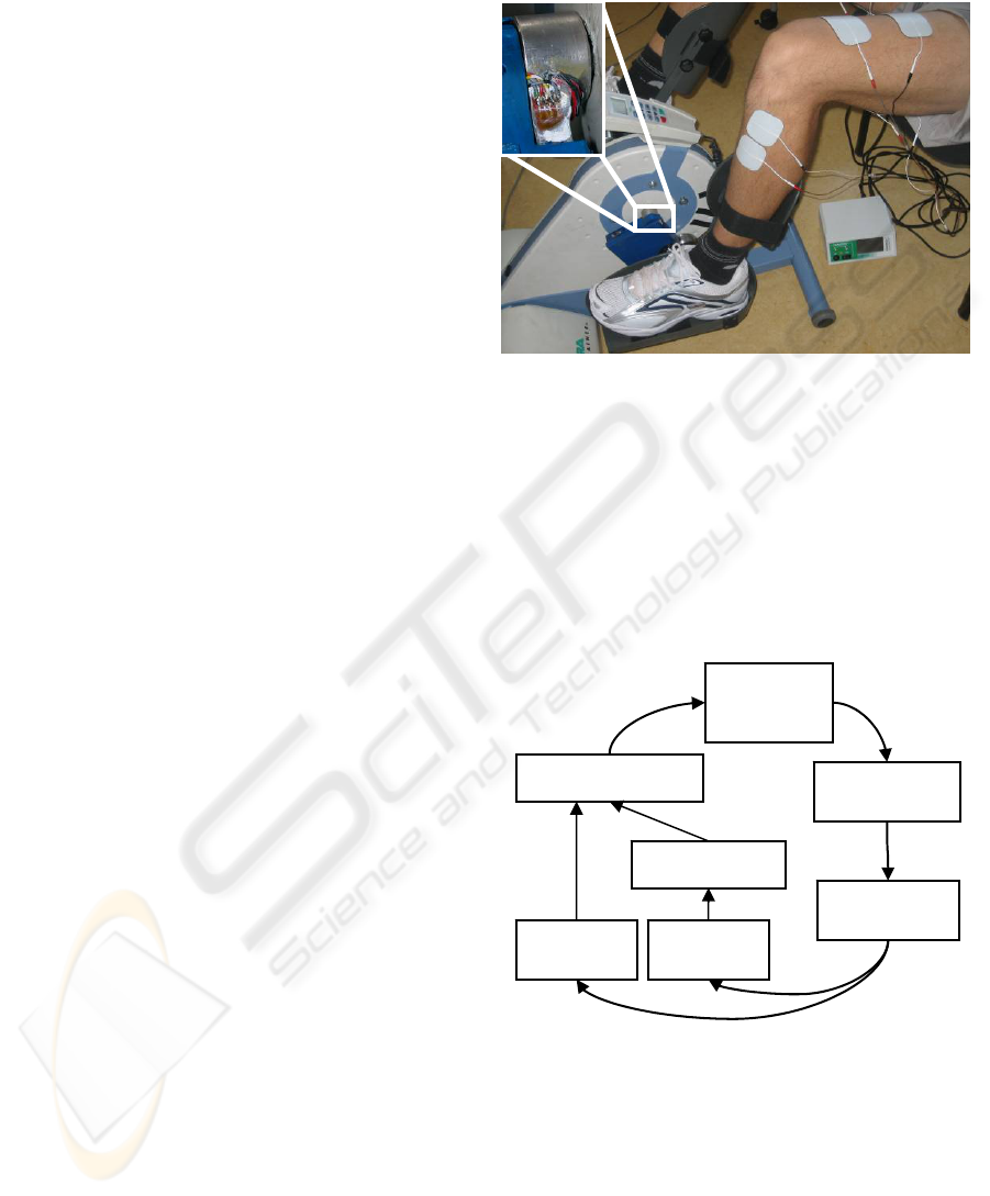
As shown in Figure 1, the cycle-ergometer was
equipped with instruments able to measure the
bending moments and the radial forces at the right
and left cranks, so that the torque can be computed
(Gföhler et al., 2001). Four Wheatstone full bridge
made up of electrical resistance strain gauges were
used to measure the strain on the right and left crank
during the cycling task. The strain gauge bridges are
conditioned through a four-channel wireless device,
which allows to transmit the signal from the rotating
shaft to the acquisition system. The angular crank
position was measured through optical encoders
mounted on the main wheel of the ergometer. More
details on the instrumentation, the acquisition chain
and the metrological characterization of the
cycle-ergometer can be found in Comolli et al., 2005
and Bocciolone, Comolli and Molteni, 2008. The
cycle-ergometer was equipped with two ankle foot
orthoses fixed to the pedals and used to stabilize the
legs and to constrain the movement to the sagittal
plane.
Figure 1: The instrumented cycle-ergometer, the wireless
device is in the box on the crank.
All the transducers were connected to a PC for data
acquisition and stimulation device control. The
real-time acquisition and control system is shown in
Figure 2. The stimulation controller set the
stimulator parameters according to the crank angle
measured in real time. Therefore, each muscle used
is activated in a particular angular phase of the
cycling movement as explained in the following.
Figure 2: The experimental setup.
2.2 Experimental Protocol
Written informed consent was obtained from all the
subjects who took part in the experiments. Three
different experimental sessions were performed and
are explained in the following paragraphs.
PC and
stimulation
controlle
r
8-channel
stimulator
Acquisition board
Subject &
ergometer
Wireless device
Angular
sensors
Force
sensors
OPTIMIZATION OF A FES CYCLING NEUROPROSTHESIS ON STROKE PATIENTS BY MEANS OF THE LEFT
AND RIGHT CRANK MEASUREMENTS
207
2.2.1 Tests During Voluntary Pedaling
First, the developed sensors were tested during
voluntary pedaling of healthy subjects. The protocol
required the subject to perform one trial lasting
8 min. The first 2 min the motor of the
cycle-ergometer was used and the subject was
cycling only passively at 30 rpm. Then, the subject
carried out a normal cycling for 2 min, trying to
keep the former velocity. After that, 2 min in which
the subject was asked to pedal using only the right
leg and 2 min using only the left one were
performed.
2.2.2 Stimulation of the Muscles
Individually
Once tested the sensors, a specific FES cycling
experimental protocol was carried out on a healthy
subject. Once the subject was sat on the ergometer
and the electrodes were placed, an initial trial to
choose the stimulation current of each muscle was
carried out. The chosen stimulation currents were set
at a value that produced a tetanic contraction using a
pulse width of 400 µs. The crank angle was set at 0°
in correspondence to the point of maximum flexion
of the left hip. During the trials 8 muscles, 4 per
each lower limbs (quadriceps, hamstrings, gluteus
maximus and tibialis anterior) were stimulated. The
stimulation strategy, i.e. the choice of the cycling
phases in which each muscle was stimulated in
respect to the crank angle, were selected following
Ferrante et al., 2005. An ON-OFF pulse width
profile was used: for all the muscles the pulse width
value was fixed at 400 µs during the ON phase and
at 0 µs during the OFF phase. The stimulation
frequency was set at 20 Hz and all the torque signals
were gathered at 500 Hz.
The subject performed a trial with a resistant
torque value of 3 Nm. The angular velocity was
maintained by the motor at a minimum value of
30 rpm during all the trials.
The trial lasted 10 min: during the initial and
final 60 s, the subject was pedaling passively. In the
intermediate part of the test, each muscle group was
individually stimulated for 60 s within its
stimulation range.
2.2.3 First Tests on Stroke Patients
Finally, a feasibility test was carried out on 2
post-acute stroke patients at the beginning of their
rehabilitation. Both the patients performed a
complete FES cycling trial according to Ferrante et
al., 2006.
2.3 Data Analysis
The measured bending moments and radial forces
were used to compute the torque at the right and left
crank. The torque was expressed as a function of the
crank angle. The median and the 5
th
-95
th
percentiles
of the right and left active torque were computed in
each test condition of the trials. Then the left and
right active torque at the crank were computed as the
difference between the torque produced during the
active phases and the one generated during passive
pedaling. The total torque was obtained adding
together the right and left torque.
3 RESULTS
3.1 Tests During Voluntary Pedaling
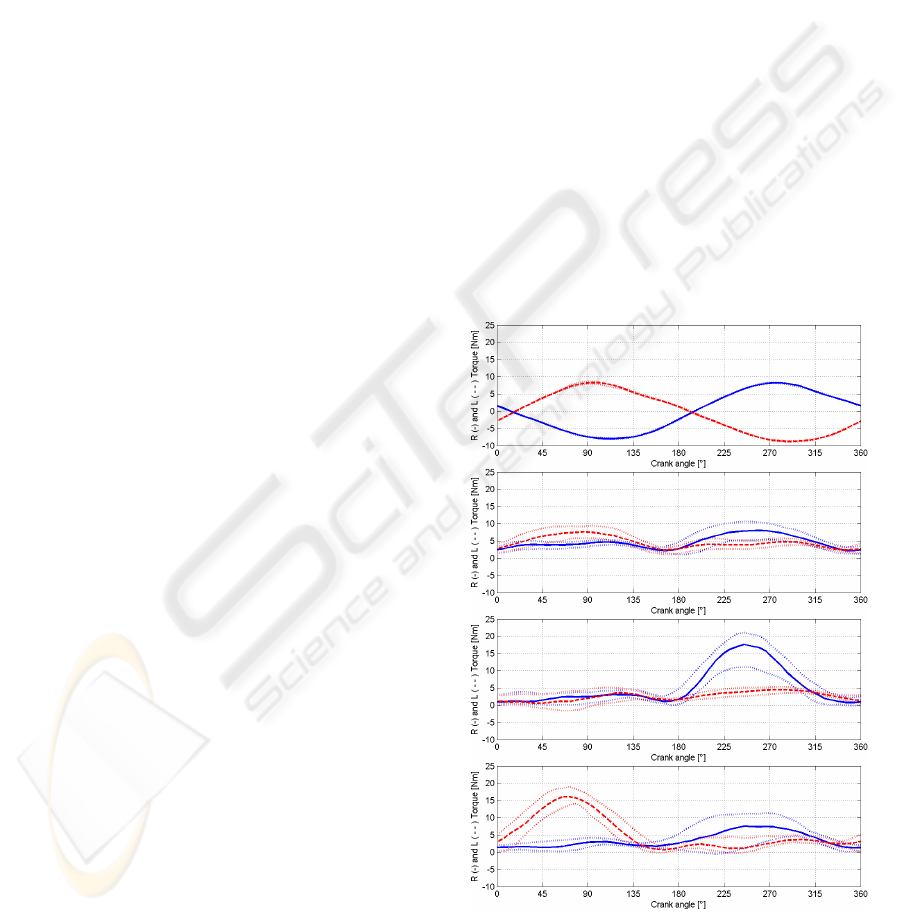
Figure 3 shows the results obtained by an healthy
subject during the voluntary pedaling protocol in
terms of the right and left active torque measured at
the crank.
Figure 3: Measurement of the right (solid line) and left
(dashed line) passive (a) and active (b,c,d) torque; the
median on 15 revolutions are shown. In dotted lines the 5
th
and 95
th
percentiles are reported.
(d) only left leg
(c) only right leg
(b) voluntary cycling
(a) Passive cycling
BIODEVICES 2008 - International Conference on Biomedical Electronics and Devices
208
In panel (a) the repeatability of the signals during
passive cycling is noticeable. In panel (b), the
subject was performing a normal pedaling. The
effect of the two legs on the right and left active
torque was quite similar in amplitude but it showed a
shift of 180° in phase. The asymmetrical cycling
presented in panels (c) and (d) highlighted a dual
behaviour. When only the left leg was cycling
actively (c), only the left active torque had a positive
peak and the right torque was quite zero during the
whole revolution. The peaks of the active torque in
panels (b), (c) and (d) were produced when the right
quadriceps was pushing. This behaviour agrees with
the fact that during a voluntary pedaling the
quadriceps muscle gives the greatest contribution to
the movement.
The results obtained in the same trials in terms of
total torque are reported in Figure 4. The panels are
referred to the same working conditions of Figure 3.
The total torque seems to be a good signal to
distinguish an asymmetry in the cycling movement.
Figure 4: Measurement of the total passive (a) and active
(b,c,d) torque; the median on 15 revolutions are shown in
solid line. The 5
th
and 95
th
percentiles are reported in
dotted lines.
3.2 Stimulation of the Muscles
Individually
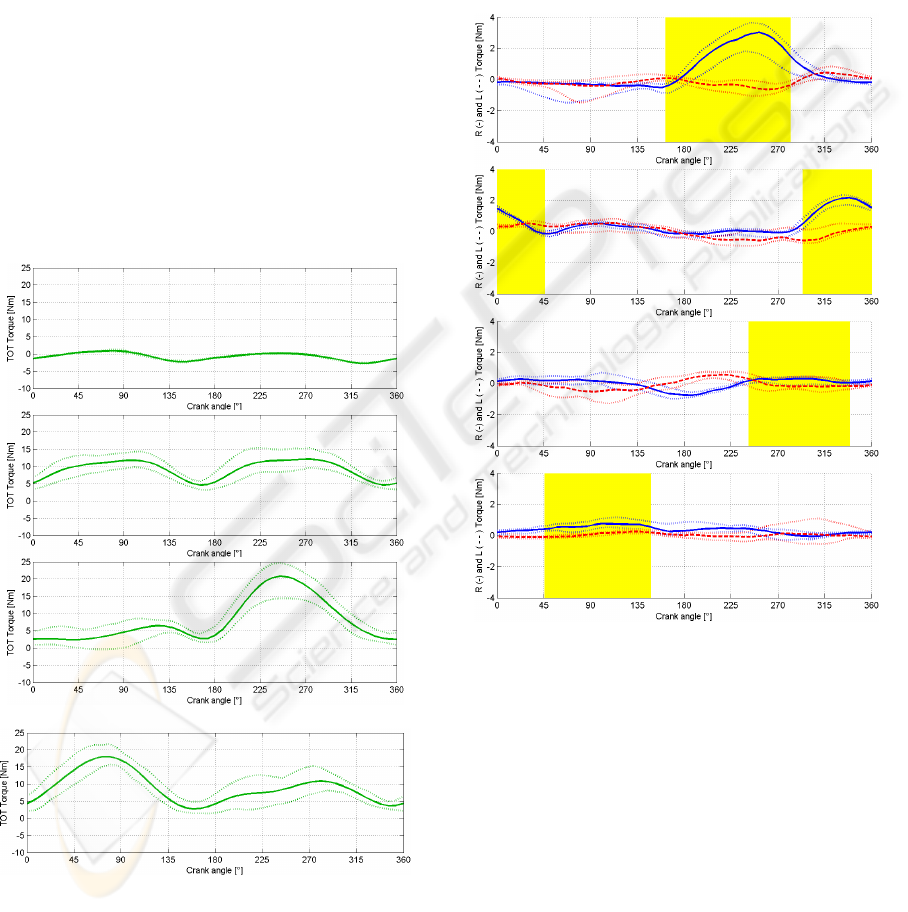
Figure 5 shows the results obtained by the healthy
subjects during the FES protocol when only the right
quadriceps (a), hamstrings (b), gluteus maximus (c)
and tibialis anterior (d) were selectively stimulated.
In all the panels of Figure 5 the grey area represent
the angular range in which the muscle was
stimulated.
Figure 5: Measurement of the right (solid line) and left
(dashed line) active torque; the median on 15 revolutions
are shown. The 5
th
and 95
th
percentiles are reported in
dotted lines.
In panels (a) and (b), a positive peak of the right
active torque can be noticed exactly in
correspondence to the muscular stimulation range.
This confirms that the muscles were stimulated
in their functional range, i.e., when they were
assisting the cycling motion.
The active left torque was nearly zero during the
whole revolution because the left leg was pedaling
passively. The gluteus and the tibialis anterior
instead did not produce an effective right active
torque at the crank, thus their contributions to the
drive torque were negligible. Such a result was
(d) only left leg
(c) only right leg
(b) voluntary cycling
(a) Passive cycling
(c) Gluteus maximus
(b) Hamstrings
(a) Quadriceps
(d) Tibialis anterior
OPTIMIZATION OF A FES CYCLING NEUROPROSTHESIS ON STROKE PATIENTS BY MEANS OF THE LEFT
AND RIGHT CRANK MEASUREMENTS
209
expected because the gluteus, as a proximal muscle
acting only on the hip, can transfer a low
contribution to the crank, while the effect of the
tibialis anterior is limited by the use of the ankle foot
orthosis.
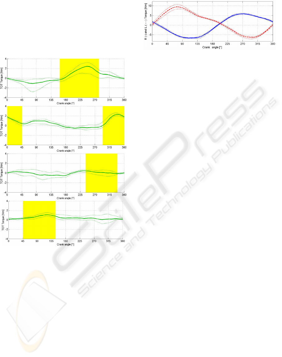
These results are confirmed by the total torque
shown in Figure 6.
Figure 6: Measurement of the total torque; the median on
15 revolutions is shown in solid line. The 5
th
and 95
th
percentiles are reported in dotted lines.
3.3 First Tests on Stroke Patients
Figure 7 reports the results obtained by a post-acute
stroke patient during a FES cycling trial performed,
stimulating 8 muscles following the stimulation
strategy described in Ferrante et al., 2006. As it is
shown in panel (a) the positive peak of the left
torque is the 40% greater then the one of the right
torque, which was correspondent to the pushing of
the impaired leg.
Figure 7: The right (solid line) and left torque (dashed
line) are reported. Results are shown in terms of the
median torque of 50 revolutions obtained by a stroke
patient during an FES cycling trial. This result suggests
the idea to use these signals as control signals for a
real-time automatic controller to minimize the asymmetry
of the movement in stroke patients.
4 CONCLUSIONS
The possibility of using a rhythmic and bilateral
movement such as cycling induced by a stimulation
pattern delivered in both legs seems to be a good
rehabilitative method for post acute stroke patients.
These patients, having an unilateral motor
impairment, need to be re-educated to the correct use
of both the lower limbs together in order to recover
the motor control symmetry in more complex and
demanding task, such as walking.
The aim of this study was to develop and test
sensors designed for a FES cycling neuroprosthesis
specific for stroke patients. Custom designed sensors
able to measure independently the torque produced
by the right and the left leg during cycling were
tested both on healthy subjects and stroke patients.
To understand the effect of the stimulation of
each muscle on the signals, a proper protocol was
defined. Each muscle was stimulated individually in
the phase of the revolution in which his action was
functional to the movement (Ferrante et al., 2005,
Ferrante et al., 2006). The results obtained suggested
that the developed sensors allowed to distinguish the
effect of the stimulation of the quadriceps and
hamstrings during the movement. Instead, the active
torque produced by the gluteus maximus and by the
tibialis anterior were quite negligible. Other
experimental trials using this second protocol
presented are now ongoing in our laboratory on
more subjects.
This study was crucial to verify that the signal to
noise ratio of the torque measurement is sufficient to
discern the torque induced by the stimulation of the
single muscle, which are an order of magnitude
lower than the ones induced by the voluntary active
pedaling.
(d) Tibialis anterior
(c) Gluteus maximus
(b) Hamstrings
(
a
)
Quadrice
p
s
BIODEVICES 2008 - International Conference on Biomedical Electronics and Devices
210

The possibility to monitor the torque at the right and
left crank represents an important step forward in the
application of FES cycling on stroke patients. It
would be possible to use the acquired torques to
monitor the unbalance of the movement on line. The
unbalance could be used as a biofeedback signal to
the patient. Thus, looking at a display where the
asymmetry is shown, he could correct the exercise
on line giving a voluntary contribution.
Alternatively, starting from this unbalance signal it
would be possible to develop a closed loop
controller aiming at the maximization of the
symmetry during the movement. The achieved
results also suggest that a simplified first version of
the controller could act only on the stimulation of
the hamstrings and quadriceps and not on the gluteus
maximus and tibialis anterior, which shown a quite
negligible effect on the right and left torque.
ACKNOWLEDGEMENTS
This work was supported by the Italian Institute of
Technology (IIT), and the Fondazione Cariplo in the
framework of the research program HINT@Lecco.
This project was realized thanks to the grant
INGENIO funded by the European Social Found,
the Welfare Ministry and by the Lombardia region.
Authors would like to acknowledge Mauro
Rossini (Villa Beretta Rehabilitation Center) for his
helpful discussion.
REFERENCES
Kralj, A., Acimović, R., Stanic, U., 1993. Enhancement of
hemiplegic patient rehabilitation by means of
functional electrical stimulation. Prosthetics and
Orthotics International, vol. 17, no. 2, pp. 107-114.
Petrofsky, J.S., 2004. Electrical stimulation:
neurophysiological basis and application. Basic and
Applied Myology, vol. 14, no. 4, pp. 205-213
Hunt, K., Stone, B., Negard, N., et al., 2004. “Control
strategies for integration of electric motor assist and
functional electrical stimulation in paraplegic cycling:
utility for exercise testing and mobile cycling. IEEE
Transactions on Neural Systems and Rehabilitation
Engineering., vol. 12, no. 1, pp. 88–101.
Lee, R.G., van Donkelaar, P., 1995. Mechanisms
underlying functional recovery following stroke. The
Canadian Journal of Neurological Sciences, vol. 22,
pp. 257-263.
Sheffler, L.R., Chae J., 2007. Neuromuscular electrical
stimulation in neurorehabilitation. Muscle Nerve, vol.
35, pp. 562-590.
Ferrante, S., Pedrocchi, A., Ferrigno, G., et al., 2006. FES
cycling treatment on hemiplegic patients: preliminary
results. In IFESS 06, 11
th
Annual Conference of the
FES Society, pp. 77-79.
Ferrante, S., Saunders, B., Duffell, L., et al., 2005.
Quantitative evaluation of stimulation strategies for
FES cycling. In IFESS 05, 10
th
International FES
Society Conference, pp. 94-96.
Gföhler, M., Angeli, T., Eberharter, T., et al., 2001. Test
bed with force-measuring crank for static and dynamic
investigations on cycling by means of functional
electrical stimulation. IEEE Transactions on Neural
Systems and Rehabilitation Engineering, vol. 9, no. 2,
pp. 169-180.
Comolli, L., Cantatore, A., Zappa, E., et al., 2005.
HINT@LECCO project: metrological characterization
of a cycle-ergometer. In SIAMOC 05, 6
th
Congress of
the Italian Society of Movement Analysis in Clinic.
Bocciolone M., Comolli L., Molteni F., 2008.
Metrological characterization of a cycle-ergometer. In
Biodevices 08, International Conference on
Biomedical Electronics and Devices.
Trumbower, R.D., Faghri, P.D., 2005. Kinematic analyses
of semireclined leg cycling in able-bodied and spinal
cord injured individuals. Spinal Cord, vol 43, no 9, pp.
543-549.
Szecsi, J., Krause, P., Krafczyk, S., Brandt, T., Straube,
A., 2007. Functional output improvement in FES
cycling by means of forced smooth pedaling. Medicine
and science in sports and exercise, vol 39, no. 5, pp.
764-80.
OPTIMIZATION OF A FES CYCLING NEUROPROSTHESIS ON STROKE PATIENTS BY MEANS OF THE LEFT
AND RIGHT CRANK MEASUREMENTS
211
