
MEMS ANTENNA FOR WIRELESS BIOMEDICAL
MICROSYSTEMS
Extremely Small Antenna for RF Receivers in Implantable Devices
P. M. Mendes
DEI, University of Minho, Campus de Azurém, 4800-058 Guimarães, Portugal
L. A. Rocha
DECE, FEUP, University of Porto, Rua Dr. Roberto Frias 4200-465 Porto, Portugal
Keywords: MEMS, Wireless Communications, Antenna, Bio-Telemetry, Implantable.
Abstract: This paper presents an extremely small antenna, together with its model, for wireless biomedical devices.
Most of the implantable devices require very small dimensions. On way to achieve it is to use
microtechnologies to obtain the required size reduction. One of the most challenging devices to integrate is
the antenna, required if we want to communicate with the device trough a wireless link. The proposed
antenna uses a MEMS structure to convert the incoming electromagnetic field into a voltage. This antenna
allows the reception of signals using a carrier in the kHz range and uses only a chip area of 2x2 mm
2
.
1 INTRODUCTION
Invasive and implantable biomedical devices used
for diagnostic and therapy, ranging from neural
prosthesis to video-capsule endoscopy (VCE)
systems, are emerging innovative technologies and
they are expected to originate significant business
activity in the near future. The success of such
systems is in part due to the advent of
microtechnologies, which made possible the
miniaturization of several sensors and actuators, as
well their integration with readout and
communication electronics.
Several people from all ages suffer from
incontinence or other urinary pathologies. The
bladder and the intestines perform their function in
an autonomous way, independently from the
individual will. However, any disorder in the healthy
behavior leads to the problem of urinary
incontinence, bladder infections, low bladder
capability and fecal incontinency.
The healthy working of the urinary tract is
essential for health and well being in general, and
even more critical for patients with lesions in the
spinal cord. In this situation, catheters are commonly
used to control the daily volume of urine inside the
bladder. However, the complications related to the
use of catheters, together with the fact that, most of
the times, the spinal segments which controls the
bladder are intact, are driving the development of
several devices to improve the control the inferior
urinary system (Gaunt and Prochazka, 2005).
The new biomedical devices offer the possibility
of improved quality of life, as well cost savings
associated with health care services. However, one
open challenge is to communicate to and from a
biomedical device placed inside the human body
with devices outside the human body. The lack of
antennas, small enough to be integrated with the
sensing microsystem, is a difficult task to overcome
because such communications must be made at
relatively low frequencies, due to live tissue signal
attenuation (Kitchen, 1993). The straightforward
solution is to increase the devices size to dimensions
where it becomes possible to integrate an antenna.
Up to now solutions, use conventional antennas
together with miniaturization techniques to achieve
the smallest antennas possible. However, the size of
such devices is usually limited by the antenna and, is
some cases, also by the batteries size.
In this paper, it is first discussed the need for
small wireless biomedical devices, paying special
attention to patients suffering from urinary
70
M. Mendes P. and A. Rocha L. (2008).
MEMS ANTENNA FOR WIRELESS BIOMEDICAL MICROSYSTEMS - Extremely Small Antenna for RF Receivers in Implantable Devices.
In Proceedings of the First International Conference on Biomedical Electronics and Devices, pages 70-75
DOI: 10.5220/0001054400700075
Copyright
c
SciTePress
pathologies. Afterwards, MEMS structures,
previously used for non-conventional front-ends,
will be introduced and investigated, having in mind
the new application. The MEMS structure will be
modeled when operating as an antenna.
2 IMPLANTABLE DEVICE
In patients with spinal cord injury at a level that
leaves the sacral segments intact, detrusor
hyperreflexia and detrusor sphincter dyssynergia
(DSD) develops after an initial phase of spinal
shock. This type of bladder is responsible for
important morbidity. The hyperreflexia impairs the
reservoir function of the bladder and the DSD causes
a high resistance against micturition. This results in
reflex incontinence, recurrent urinary tract infection,
and autonomic dysreflexia in high lesions and
threatens these patients with renal failure.
All of these severe disturbances may be well
managed by sacral deafferentation (SDAF) and
implantation of an anterior root stimulator (SARS).
2.1 Electrical Stimulation
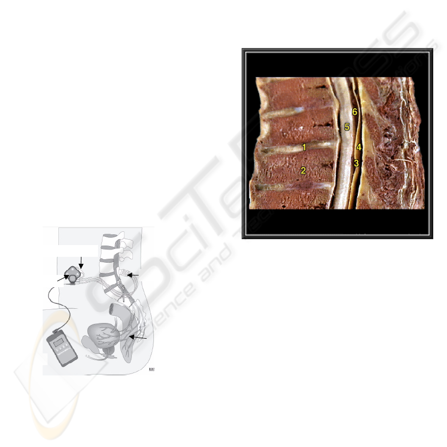
Fig. 1 shows the commonly adopted system
architecture to control the inferior urinary system.
Si
g
nal
g
enerator
Internal inductor
External inductor
Cuff electrode
Transmission cables
Figure 1: Schematic view of the overall system used for
bladder control.
The system has a signal generator that generates the
appropriate stimulus to activate, e.g., the bladder.
That stimulus is transmitted to the external coil,
which induces the signal in the internal coil.
Reaching the biologic environment, a receiver
module delivers the stimulus trough the transmission
cables that carry the signal to the cuff electrode.
Since the internal coil is placed in the frontal region and
the electrodes are in the back, the transmission cables must
go through the body and are one main cause of system
failure. Moreover, the existence of these cables requires a
small opening in the duramater, not good for the spinal
cord integrity. One main benefit of the microsystem
approach is the possibility to avoid cables trespassing the
duramater.
2.2 Anatomy of spinal cord
Fig. 2 shows the anatomy of the spinal cord. This is
the place where the microsystem must be designed
to operate.
Figure 2: Spinal cord cut, showing the region where the
microdevice must be placed (1– intervertebral disk, 2-
vertebral body, 3- duramater, 4– epidural space, 5- spinal
medulla, 6- subarachnoid space).
From the figure we see that the microdevice must fit
in a very small region, inside the duramater. It can
be placed in two places, or in region 4 or in region 6.
The best place is 6, the subarachnoid space, since the
duramater can be totally closed after surgical
intervention. The available space in region 6 varies
between 3 mm and 9 mm [4]. This is room enough
to accommodate a small microdevice.
The conventional surgical procedure requires the
duramater opening to place the electrodes in contact
with the sacral roots (Fig. 3).
The electrodes are connected to the leads coming
from the stimulator, leaving a small opening in the
duramater. As we can see from Fig. 3, there is plenty
of room to place the microsystem in the implant
region.
MEMS ANTENNA FOR WIRELESS BIOMEDICAL MICROSYSTEMS - Extremely Small Antenna for RF Receivers in
Implantable Devices
71

Figure 3: Placement of electrodes (testing the nerves to be
used).
3 MICROSYSTEM
The need to reduce the failure associated with long
wires that are used, to reduce the risk of infection or
shifts in the wires is driving researchers to find a
solution using microthecnologies. Also, and very
important, is the internment period associated with
the surgical intervention. Due to the highly invasive
intervention that is required using the traditional
technique, the patients, even when there are no
complications, are required to stay a few days in the
hospital. The availability of a device to allow a less
invasive method would be more comfortable for the
patient, reducing also the hospital costs associated to
the surgery.
To make it possible to use, the device must be
small enough to fit inside the spinal cord, it must be
able to deliver the required stimulus (power and
timing) and it must be possible to communicate with
the device using a radio-frequency signal. This
requires the use of a microsystem completely
integrated, from sensors to communications, thus
requiring the use of integrated antennas. Moreover,
the antenna integration requires the availability of an
electrically small antenna fabricated on materials
compatible with the fabrication of integrated
circuits. This integration requires the use MEMS
techniques, like micromachining and wafer level
packaging.
The microsystem must be designed taking into
account the place where it will be required to operate
because we cannot change the human body electrical
system. As we saw, the human body anatomy will
place constrains on available room for the
microdevice, on power required for system powering
and/or telemetry, and on required power for
stimulation.
The final device to implant must not fail during its
lifetime, must be stable and must be biocompatible
(citotoxity, sensibilization, genotoxity, chronic
toxity, carciginosity, and intracutaneous irritation).
3.1 CMOS Microsystem
The most suitable technology to implement the
microsystem is the CMOS technology. It is the
cheapest technology, with low power consumption,
and adequate for this device since there are no high
power delivery requirements.
In face of constrains, we have three solutions to
design the microsystem. One is to design a chip,
which acts only as a stimulus converter. The second
option is to implement a full microsystem, with the
ability to be remotely powered and controlled
(Piella, 2001). The third is to use a microsystem with
local power and a wireless receiver (Carmo et al.,
2006). The first solution is the simplest, however the
second and third are more flexible and, despite its
higher complexity, fit in the available room for
implant. The main drawback of third solution is the
need of a local source of energy, battery or energy
harvesting.
3.2 Wireless link
Antenna integration is a hard task to accomplish
since it requires joining the knowledge from
antennas, microwaves, circuit design, and materials.
Moreover, the on-chip antenna integration requires
an electrically small antenna, due to wafer cost and
devices size constrains, and operating on a substrate
that was not initially intended for that purpose
(Mendes and Correia, 2007).
Despite it is used to transmit data or to power the
device, it is necessary to have a wireless link
operating at one frequency. As is well known, the
human body shows higher attenuation to higher
frequencies. This means that, the lower the
frequency, the higher the power we receive in the
implant. Moreover, the attenuation is highly
dependent on water content in tissues. The water
content depends on the type of tissue and part of the
body.
Micro-Electro-Mechanical Systems (MEMS) are
becoming an available option for RF communication
systems since they can offer, simultaneously,
devices with improved performance and they use IC-
compatible materials, allowing their integration in a
silicon chip, side by side with semiconductor
Electrodes
N
erves under test
BIODEVICES 2008 - International Conference on Biomedical Electronics and Devices
72
circuits. Up to now, MEMS have been used for
antenna applications to obtain non-conventional
front-ends with improved, or new characteristics.
However, some preliminary tests have shown that
some MEMS structures could have the ability to
operate as an antenna itself and this solution would
have the potential to be smaller than the
conventional antennas.
The basic principle of micromachined
cantilevers offers an interesting possibility to
measure a variety of physical parameters (Lange et
al., 2002). When used as a sensor, a MEMS
structure requires the use of a sensing mechanism
and the most widely used is the capacitive method.
The moving structure, and a fixed plate, forms a
parallel plate capacitor, where the structure
movement is translated into a capacity change.
4 MEMS ANTENNA
4.1 Cantilever Antenna
The U-shaped cantilever, proposed to detect a time-
varying magnetic field, is presented in Fig. 4.
I
B
V
I
B
V
Figure 4: Cantilever used to detect a time-varying
magnetic field.
To measure magnetic fields with cantilever
structures, the Lorentz-force is used on a current
carrying lead (Keplinger, 2004). A cantilever of this
type measures only the magnetic flux density in the
direction parallel to the arms of the cantilever, i. e.,
x-axis of Fig. 4. The Lorentz-force acting on a lead
is used to bend a micromachined cantilever.
Deflections, which are small compared to the length
of the cantilever, are a directly proportional measure
of the applied force. To reach the highest possible
sensitivity it is advisable to use a resonant
mechanism, where the cantilever is excited by an
AC current with a frequency equal to an eigen-
frequency of the elastic structure. Due to the high
quality factors of Si structures, which are at least
several hundred, this is an efficient way to enhance
the sensitivity.
Electromagnetic field can be sensed using an
optical, capacitive, or piezoelectric sensing solution.
The most attractive options are capacitive and
piezoelectric. These solutions can be easily
integrated with the MEMS structure and have the
potential for low power consumption (except the
optical solution). Since the desirable displacement
depends on structure dimensions and material
properties, electrostatic actuation can be used as the
actuation mechanism for MEMS micro-antennas.
However, if large displacements are required or if
the MEMS structure area becomes too small for
capacitive detection, the use of a piezoelectric
material can be the solution since it can act both as
sensor and actuator. Moreover, the operation is only
voltage based, leading to low power driving
operation. Furthermore, it produces a voltage in
response to a deflection leading to simple readout
electronics.
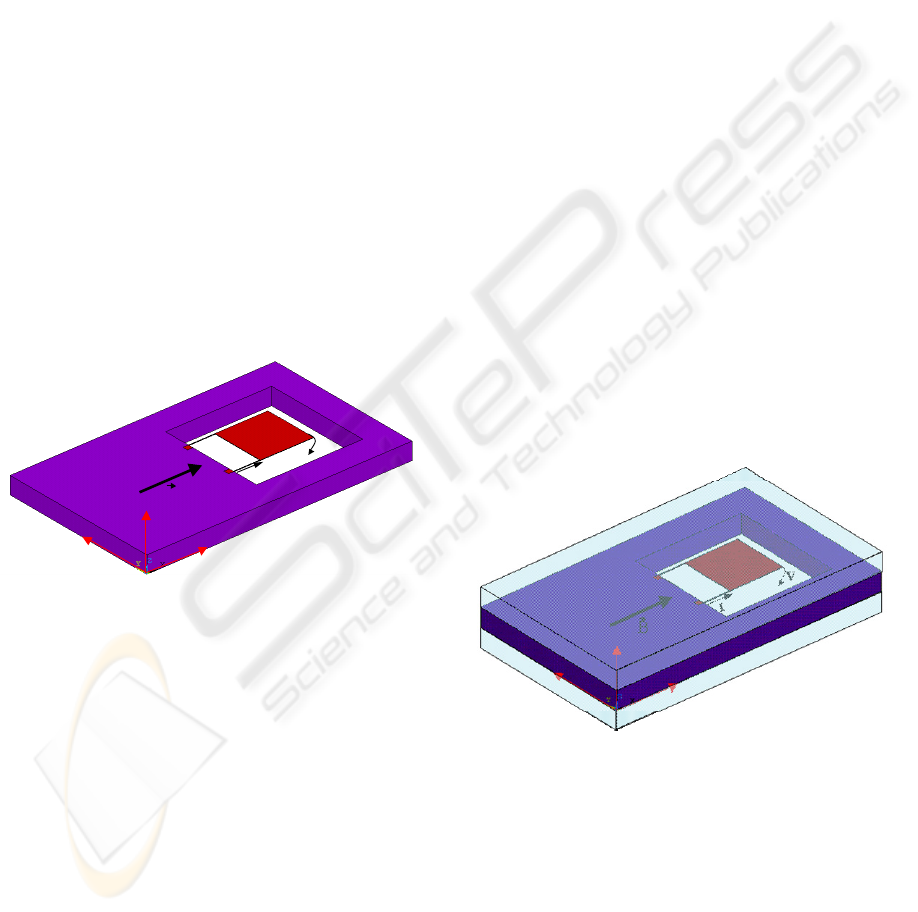
4.2 Antenna Packaging
Fig. 5 shows a solution to integrate the proposed
antenna structure. It consists of three stacked wafers,
where the bottom wafer is used to place the reading
and controlling electronics, the middle wafer is used
to implement the U-shaped cantilever, and the
bottom wafer encapsulates the device, enabling a
very small microsystem with integrated antenna.
Figure 5: Use of WLCSP to integrate the proposed MEMS
antenna.
4.3 Antenna Modelling
The proposed MEMS structures were engineered to
have the desired electrical and geometrical
properties, as well the requirements to be used in a
post-process module compatible with integrated
circuit (IC) fabrication.
MEMS ANTENNA FOR WIRELESS BIOMEDICAL MICROSYSTEMS - Extremely Small Antenna for RF Receivers in
Implantable Devices
73
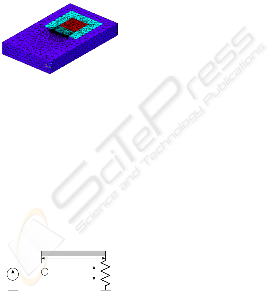
Fig. 6 shows the 3D FEM (finite element
modelling) model being used to analyse the
receiving properties for a cantilever operating as an
antenna. FEM modelling is a very powerful
technique to predict the interaction between different
domains (electrical, mechanical, and
electromagnetic).
Figure 6: Model of structure used to sense the
electromagnetic field.
However, it is also very time consuming and, in this case,
very complex to set up a simulation and get data we can
rely on it. In this way, a simple model was derived to
understand the requirements and potentials of a structure
like this one, if operated as an antenna.
4.4 Modulation Modelling
Considering the structure proposed in Fig. 4, we can
represent it using the simplified model of Fig. 7. The
electrical behaviour is modelled by the beam of
length L and the current I, whereas the mechanical
behaviour can be described using the spring k.
Considering that the magnetic field, B, is applied
perpendicularly to the current I, trough the length L,
the resulting Lorentz force, F
L
, will be given by:
LIBF
L
)(
×
=
(1)
The MEMS structure will move when the
Lorentz force becomes higher then the elastic force
(Rocha et al., 2004).
k
I
L
B
X
u
k
I
L
B
X
u
Figure 7: Simplified model of a cantilever operating as an
antenna.
Due to the applied force F
L
, the structure will move,
and the following equation can be written:
eL
FkuLIBF =
=
×
=
)(
(2)
where F
e
stands for elastic force, u for displacement
and k is the spring constant of the structure. From
the previous equation, we can find the displacement:
k
LIB
u
)(
×
=
(3)
Independent of the detection method, optical or
capacitive, the displacement will give origin to a
received voltage, V
R
, which will be proportional to
the applied magnetic field, B.
BuV
R
∝
∝
(4)
If the magnetic field was originated by a
modulated signal:
))()(2cos()()( ttftAtB
φ
π
+
=
(5)
the received voltage will be:
))()(2cos()()( ttftA
k
LI
GtV
R
φπ
+=
(6)
where G represent the system gain.
4.5 Antenna Analysis
From equation 6 it is possible to conclude that the
proposed device will actuate as a signal receiver if
the spectral properties of the modulated signal are
chosen to fall inside the device operating frequency
limit.
The first parameter requiring analysis is the force
such a structure can produce when in presence of a
magnetic field. From equation 2, if we consider
I = 100 mA, L = 1,1 mm and B = 10 mT, then the
resulting force will be 1.1 μN. This is enough force
to produce movement in this kind of structure.
A key advantage of this solution is that it can
deliver gain trough the increase of the current I. If
the resistivity of the beam material is kept low, then
we can have a low power device, since the voltage
drop will be small.
The other requirement is that the modulation
type must be selected carefully. Even if the
modulating signal bandwidth is inside the MEMS
device bandwidth, if we chose, e.g., FSK, the
BIODEVICES 2008 - International Conference on Biomedical Electronics and Devices
74

resulting bandwidth may be outside the structure
bandwidth due to the instantaneous required
frequency shifts. In this way, a continuous
modulating method must be used instead.
To check the ability to operate as a radiating
element, some preliminary tests were also
conducted, where it was used a scaled model of the
proposed structure. A commercially available
magnetic sensor was connected to a signal
acquisition board that was connected to a personal
computer. A current was injected into a scaled
structure of Fig. 4, and the signal was recorded with
the magnetic sensor. When the transmitting structure
was oscillating at 100 KHz, it was possible to easily
detect that signal with the magnetic sensor.
5 CONCLUSIONS
This paper described the design, and modelling of
chip-size MEMS antennas for short-range wireless
microsystems. These antennas allow the fabrication
of an implantable microsystem with integrated
wireless communications. The antenna integration is
based on wafer-level packaging techniques, which
enables the integration of new materials with the
standard silicon processing steps, as well the
fabrication of complex three-dimensional structures,
in an economically acceptable way.
MEMS were explored as a new solution to
obtain structures that can sense electromagnetic
fields. Thus, instead of having the need to design
very advanced antenna structures to achieve antenna
size reduction, the standard MEMS devices, e.g.
cantilevers, will be used to save system space and
improve system integration. A novel electrically
very small antenna using MEMS structures, and a
model to describe the operation of that structure; is
presented.
The present solution envisions power saving,
smaller volume, lower cost, and increased system
lifetime, which are very important features in
biomedical microsystems for diagnosis and therapy.
ACKNOWLEDGEMENTS
We would like to acknowledge Medical Doctor
Paulo Vale for his support in this research work.
REFERENCES
Carmo, J. P., Mendes, P..M., Couto, C., Correia, J.H.,
2006, “5.7 GHz on-chip antenna/RF CMOS
transceiver for wireless sensors network,” Journal
Sensors and Actuators A, Elsevier Science, Vol. 132,
pp. 47-51,
Gaunt, R. A, and Prochazka, A., 2005, “Control of urinary
bladder function with devices: successes and failures,”
Progress in Brain Research, Elsevier, Vol. 152, pp.
163-194.
Keplinger, F., Kvasnica, S., Jachimowicz, A., Kohl, F.,
Steurer, J., and Hauser, H., 2004, “Lorentz force based
magnetic field sensor with optical readout,” Sens.
Actuators A, 110, (1–3):112–118.
Kitchen, R, 1993, RF Radiation Safety Handbook,
Butterworth-Heinemann.
Lange, D., Brand, O., and Baltes, H., 2002, CMOS
Cantilever Sensor Systems: Atomic Force Microscopy
and Gas Sensing Applications., Springer.
Mendes, P. .M., and Coreeia, J. H., 2007, "MEMS Micro-
Antennas for Wireless Biomedical Systems," in
"Wireless Communications Research Trends", ISBN:
1-60021-674-9, 2007, edited by Tong S. Lee, Nova
Publishers.
Piella, J. P., 2001, Energy management, wireless and
system solutions solutions for highly intregated
implantable devices. PhD Thesis, Universitat
Autónoma de Barcelona, Barcelona.
Rocha, L. A., Cretu, E., Wolffenbuttel, R. F. 2004,
“Analysis and Analytical Modeling of Static Pull-In
With Application to MEMS-Based Voltage Reference
and Process Monitoring,” Journal Of
Microelectromechanical Systems, Vol. 13, No. 2, pp.
342-354.
MEMS ANTENNA FOR WIRELESS BIOMEDICAL MICROSYSTEMS - Extremely Small Antenna for RF Receivers in
Implantable Devices
75
