
CONSIDERATIONS ON IMPROVING THE DESIGN OF CUFF
ELECTRODE FOR ENG RECORDING
Geometrical Approach, Dedicated IC, Sensitivity and Noise Rejection
Fabien Soulier, Lionel Gouyet, Guy Cath´ebras, Serge Bernard
David Guiraud and Yves Bertrand
LIRMM, Universit´e Montpellier II - CNRS - INRIA, 161 rue Ada, 34392 Montpellier, France
Keywords:
Multipolar cuff electrode, regular tessellation, electroneurogram, action potential, Laplacian, selectivity,
ASIC, multi-input differential amplifier.
Abstract:
Cuff electrodes have several advantages for in situ recording of ENG signal. They are easy to implant and
not very invasive for the patient. Nevertheless, they are subject to parasitic background noise, especially the
EMG generated by the muscles. We show that the use of large numbers of poles can increase the sensitivity
of cuff electrodes as well as their selectivity with respect to a efficient noise rejection. We investigate several
configurations and compare the performances of a tripolar cuff electrode versus a multipolar one in numerical
simulation.
One the other hand the use of cuff electrodes leads to the recording of the sum of the signals generated by all
the axons within the nerve. This puts in evidence the need of signal separation techniques that require a large
amount of information. Again, we show that multipolar electrodes can solve this problem since poles can be
switched one to another, provided that they are distributed along a regular tessellation.
Finally, we present the structure of an ASIC preamplifier aimed to obtain the Laplacian of the potential by
spatial filtering and rejecting low-frequency noise..
1 INTRODUCTION
Functional Electrical Stimulation (FES) techniques
are used to restore motion or sensitive functions in
people with neural system pathologieslike spinal cord
injury. These techniques consist in generating artifi-
cial contraction by electrical stimulation. In FES sys-
tem a direct opened loop control doesn’t allow effi-
cient stimulation. In order to provide a loopback con-
trol we need sensory information (force, contact...)
(Djilas et al., 2006). An attractive solution consists
in using the natural sensors. The sensory information
is propagated by associated afferent fibers and can be
recorded as an electric potential variation, the elec-
troneurogram (ENG).
Unfortunately, in peripheral nerves the complete
nerve activity due to the large number of axons makes
the extraction of the studied signal particularly hard.
Moreover the sensory signal seen through the nerve is
a very low amplitude signal compared with the ampli-
tude of parasitic signals. For instance, on a monopolar
recording, EMG created by muscle activity have am-
plitude about three orders of magnitude higher than
the ENG. In this context, the two main objectives to
be able to exploit natural sensors are:
• to find a solution to separate the useful informa-
tion from the complete ENG signal;
• to reject the parasitic external signals.
The classical solution consists in using multipolar
electrodes, but from tripole (Ramachandran et al.,
2005) to nine pole electrode (Winter et al., 2000; Tay-
lor et al., 2004), the selectivity of the neural informa-
tion is not efficient enough to be suitable in closed
loop FES system. To achieve both a better sensitivity
and efficient background noise rejection we propose
a new configuration of the cuff electrode with a large
number of poles regularly distributed onto the cuff. In
this configuration, a group of poles can behave, with
suitable low level analog signal processing, like a kind
of a directive antenna. Moreover, the large number
of poles will allow enough channels in order to ap-
ply source separation signal processing on the ENG.
Of course, the directivity of the sensor relies on the
quality of the subsequent low-level analog signal pro-
cessing.
In this paper, we first show how to generalize the
preprocessing operations on the recorded signal from
180
Soulier F., Gouyet L., Cathébras G., Bernard S., Guiraud D. and Bertrand Y. (2008).
CONSIDERATIONS ON IMPROVING THE DESIGN OF CUFF ELECTRODE FOR ENG RECORDING - Geometrical Approach, Dedicated IC, Sensitivity
and Noise Rejection.
In Proceedings of the First International Conference on Biomedical Electronics and Devices, pages 180-185
DOI: 10.5220/0001056301800185
Copyright
c
SciTePress
tripolar to multipolar configuration using the Lapla-
cian formalism. Then we discuss on the optimal
pole placement around the nerve regarding tessella-
tion methods. Both the electrode configuration and
the associated preprocessing circuit result from this
pole distribution and must be taken into account. We
particularly focus on the hexagonal seven-pole elec-
trode, presenting the associated seven input preampli-
fier and preliminary simulation results.
2 EMG NOISE REJECTION
Cuff electrodes have been the most used for ENG
recording in the last ten years (Haugland et al., 1994;
Jensen et al., 2002; Andreasen and Struijk, 2002).
They are relatively easy to implant, they are not in-
vasive for the nerve and implantation is very stable
and thus allows chronic experiments. ENG can be
a a
V
2
V
0
V
1
2R
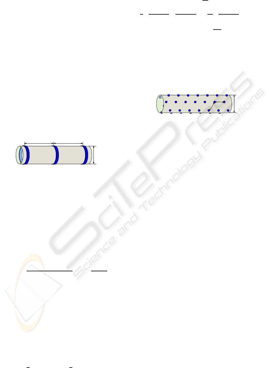
Figure 1: Tripolar electrode cuff model.
recorded as the potential difference created on the
electrodes by the charges associated to the action
potentials (AP) propagating along the nerve fibers.
Fig. 1 shows a typical tripolar cuff electrode. When
recording with this kind of electrode, a classic method
to reject parasitic signals consists in calculating the
average of the potential differences between the cen-
tral pole and each of the outer poles (Struijk and
Thomsen, 1995; Pflaum et al., 1996):
V
rec
=
(V
0
−V
1
) +(V
0
−V
2
)
2
= V
0
−
V
1
+V
2
2
(1)
The last expression shows that this operation consists
in:
1. averaging the signal on the outer poles, i.e. apply-
ing a low-pass spatial filter.
2. subtracting the result to the signal of the central
pole, keeping only the high spatial frequencies.
Therefore, the recorded V
rec
signal can be considered
as spatial high-pass filtered.
More precisely, this filter is a second-order one
considering that the expressions
1
a
(V
2
−V
0
) and
1
a
(V
0
−V
1
) (2)
evaluate the first derivative
dV
dx
. Thus the difference
1
a
(V
2
−V
0
)
a
−
(V
0
−V
1
)
a
=
2
a
2
(V
1
+V
2
)
2
−V
0
(3)
denotes the second derivative
d
2
V
dx
2
that is the one-
dimensional Laplacian of the potential. We can iden-
tify in the last expression the equation (1) without the
known constant factor −2a
−2
.
Laplacian filters can reject both homogeneous po-
tentials and linearly varyingones like those created by
far EMG sources. The purpose of this new design is to
build two-dimensional Laplacian using more poles to
obtain isotropic rejection.
2R
d
d
Figure 2: Multipolar electrode cuff model.
3 POSITIONING THE POLES
A tripolar cuff electrode (Demosthenous and Triantis,
2005) provides only one recording which is the su-
perposition of all action potentials “seen” by the elec-
trode at a given moment. The use of several poles on
a cuff electrode (see Fig. 2) could allow us to record
more signals, thus increase the quantity of neural data
and facilitate the signal post-processing on the record-
ing system.
In order to achieve optimal placement of poles, we
must pay attention to three constraints:
1. The electrodes have to be placed all around the
nerve, thus the poles have to be distributed onto
the whole surface of the cuff.
2. The poles have to be equally spaced to simplify
electronics in charge of analog signal preprocess-
ing (weight coefficients in Laplacian preampli-
fier).
3. They have to be able to be substituted one to each
other, so we take benefits of the maximum mea-
surement locations, allowing powerful signal pro-
cessing.
Since the cylindric shape of the cuff results from the
wrapping of an initially plane device, these condi-
tions imply to look for a regular tessellation of the
plane as the positions of the poles or, more precisely,
tessellations composed of regular polygons symmet-
rically tiling the plane. It is well known that there are
exactly three type of regular tessellations (Weisstein,
2002). They can be specified using the Schl¨afli sym-
bols: {3,6}, {4,4} and {6,3}.
CONSIDERATIONS ON IMPROVING THE DESIGN OF CUFF ELECTRODE FOR ENG RECORDING - Geometrical
Approach, Dedicated IC, Sensitivity and Noise Rejection
181
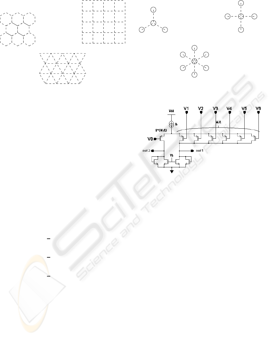
{6,3} {4,4}
{3,6}
Figure 3: There are exactly three regular tessellations com-
posed of regular polygons symmetrically tiling the plane.
The first symbol in the Schl¨afli notation denotes the
shape of the patch (triangle, square or hexagon). On
the figure 3, each vertex corresponds to a pole. Each
of them being surrounded by a number of equidistant
poles given by the second Schl¨afli symbol, respec-
tively 6, 4 and 3.
From the previous tessellations, one can build
three kinds of electrodes by selecting one central pole
and its closest neighbors. Namely, we can define a
mesh of:
• triangular 4-pole electrodes,
• squared 5-pole electrodes,
• hexagonal 7-pole electrodes.
These candidates can be seen on the figure 4 and the
resulting expressions for the Laplacian are:
V
rec
= V
0
−
1
3
3
∑
i=1
V
i
for {6,3} (4)
V
rec
= V
0
−
1
4
4
∑
i=1
V
i
for {4,4} (5)
V
rec
= V
0
−
1
6
6
∑
i=1
V
i
for {3,6} (6)
One can notice that the {4,4} configuration corre-
spond to the 2D Laplacian filter used in image pro-
cessing (Gonzales and Woods, 1992).
4 ENG AMPLIFIER
Because of the very low level of processed signals we
propose to perform the maximum of signal processing
as close as possible to the nerve. The more complex
operations to be considered are those with the hexag-
onal electrode.
{6,3}
V
3
V
0
V
1
V
2
{6,3}
{4,4}
V
4
V
2
V
6
V
0
V
1
V
1
V
0
V
2
V
3
V
4
V
5
V
6
{3,6}
Figure 4: Three possible configurations of electrodes.
Figure 5: Seven input preamplifier.
For this purpose, we have designed a seven channels
ASIC. Each channel compute a weighted difference
between the measurement point and the six closest
surrounding points. This is done in the analog do-
main using the preamplifier shown on figure 5. This
preamplifier is build around a differential pair whose
negative input transistor was split into six transistors
(six times smaller, of course). It has a voltage gain
that is about 100 and it is followed by an instrumen-
tation amplifier whose gain is configurable between
6dB and 80dB. Each channel is composed of one
preamplifier followed by an instrumentation ampli-
fier.
This circuit was designed to give an input-referred
noise below 1µV
rms
, a CMMR above 60 dB and a suffi-
cient gain, i.e greater than 60 dB ; all these parameters
in the bandwidth of interest (1Hz ≤ f ≤ 3kHz). The
performances expected for this amplifier are given
in Table 1 (the noise is measured in the band 1Hz-
3kHz).
A microphotography of the fabricated circuit is
presented Fig. 6. This circuit was designed in CMOS
AMS 0.35-µm technology.
BIODEVICES 2008 - International Conference on Biomedical Electronics and Devices
182
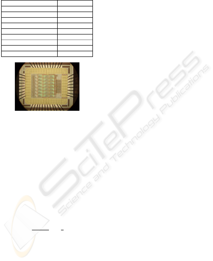
Table 1: Amplifier characteristics (simulation).
Active area (7 channels) 1.16mm
2
Supply voltage 3.3 V
DC Current (Preamp) 20µA
Voltage gain (Preamp) 100 (40 dB)
CMRR (Preamp) 80dB (10 kHz)
Voltage gain (Inst amp) 2 ≤ G ≤ 10000
CMRR (Full amp) 80dB (10kHz)
Input-ref. noise (Preamp) 0.672µV RMS
Input-ref. noise (Full amp) 0.677µV RMS
Bandwidth (Full amp) 76kHz
Figure 6: Microphotograph of the seven-channel prototype.
5 NUMERICAL RESULTS
5.1 Action Potential Modeling
In order to evaluate the performances of multipolar
electrodes, we need a model for the extracellular elec-
tric field created by an action potential. Let us con-
sider a 10µm diameter myelinated axon. Its Ranvier
nodes are 1µm long, while their diameter is 6 µm and
their spacing is 1 mm. Let us call Ω the center of the
Ranvier node. When the AP is present at this node, we
can model it as a 6 µm diameter circle, perpendicular
to the axon axis, with a positive charge +q at its cen-
ter (Ω) and a negative charge −q spread on the circle.
The potential created at a point M of the space by this
AP can be approximated by:
V(M) =
qa
2
8πε
0
ε
r
r
3
1−
3
2
sin
2
ψ
(7)
In this expression, a is the radius of the Ranvier node
(3µm), r is the distance between Ω and M, while ψ
is the angle between the axe of the axon and
−−→
ΩM.
This approximation, valid for r ≫ a, is in good ac-
cordance with measurements. In particular, we can
see thatV(M) is negative for ψ = π/2 (Stein, 1980, p.
81). Last, q can be easily estimated from the charac-
teristics of the Ranvier node. For this study, we took
q ≃ 20fC and ε
r
≃ 80.
The model given by the equation 7 was used to
evaluate the sensitivity of the electrodes to action po-
tentials occurring inside the nerve. For the evaluation
of the rejection of parasitic signals, we must first re-
call that EMG are also action potentials, creating the
same kind of electric field. But, in this case, we can-
not make any assumption on the value of ψ. So, to
evaluate the external sensitivity of electrodes, we only
used a 1/r
3
model, unable to give voltages, but suffi-
cient to compare the sensitivities of the electrodes.
We have limited the numerical study to the com-
parison of the classical tripolar cuff with the heptapo-
lar (hexagonal shape {3,6}) electrode. We have also
studied the effect of the wrapping to the performance
of the heptapolar electrode: we consider a plane elec-
trode and then a cylinder-wrapped one.
Given the position of a single AP we can easily
calculate the induced potential on each pole of the
cuff, since they are very small. For the tripolar cuff,
we need to average the potential on each ring. This
lead to an elliptic integral we have solved using nu-
merical methods.
5.2 Tripolar and Heptapolar Electrodes
Models
In the following, we compare a tripolar cuff electrode,
whose diameter is 2R = 3mm and ring spacing is
a = 4R, with one patch of the hexagonal cuff. To get
comparable results, this hexagonal cuff has the same
diameter (2R) and the spacing between poles is d = R.
Since this patch is partially wrapped around the nerve,
we considered also another patch perfectly flat.
For all the calculations, the coordinates were fixed
as follow: the origin O is at the center of the cuff elec-
trode. The Ox axis is the axis of the nerve (and, obvi-
ously, of the cuff). The Oy axis passes by the center
of the considered patch (which is perpendicular to this
axe). Last the Oz axe is placed to form a direct trihe-
dron with Ox and Oy.
5.3 Internal Sensitivity
Figure 7 shows the radial sensitivities of the three
electrodes (tripolar cuff, planar hexagonal patch and
wrapped hexagonal patch) that we compare. The ver-
tical axis is the value of V
rec
(in dBµV) calculated for
an AP placed on the Oy axis, at abscissa yR. The graph
shows clearly that while the sensitivity of the tripolar
cuff is quasi constant on the section of the nerve, the
sensitivity of the hexagonal patch is far higher (up to
30 dB) when considering an AP located between the
center of the patch and the center of the cuff.
CONSIDERATIONS ON IMPROVING THE DESIGN OF CUFF ELECTRODE FOR ENG RECORDING - Geometrical
Approach, Dedicated IC, Sensitivity and Noise Rejection
183
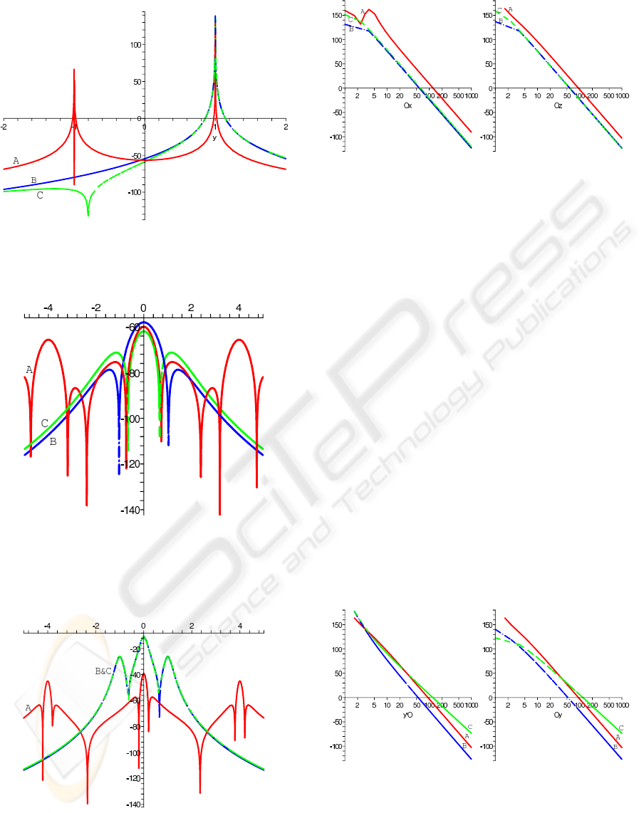
Figure 7: Radial sensitivities of (A) a tripolar cuff elec-
trode, (B) a planar hexagonal patch and (C) a bent hexago-
nal patch. The vertical axis is in dB µV and the unit for the
horizontal axis is the radius R of the electrode.
Figure 8: Longitudinal sensitivities on the axe of (A) a
tripolar cuff electrode, (B) a planar hexagonal patch and (C)
a bent hexagonal patch. The vertical axis is in dB µV and
the unit for the horizontal axis is the radius R of the elec-
trode.
Figure 9: Longitudinal sensitivities on an off-center (80 %
of R) axis of (A) a tripolar cuff electrode, (B) a planar
hexagonal patch and (C) a bent hexagonal patch. The ver-
tical axis is in dBµV and the unit for the horizontal axis is
the radius R of the electrode.
Figure 10: External relative sensitivity along Ox and Oz
axes for (A) a tripolar cuff electrode, (B) a planar hexagonal
patch and (C) a bent hexagonal patch. The vertical axis is
in dB and the unit for the horizontal axis is the radius R of
the electrode.
Figures 8 and 9 show the longitudinal sensitivities of
the three considered electrodes. On figure 8, the sen-
sitivity is computed for an AP placed on the Ox axe,
while, on figure 9, the AP is placed on a line, parallel
to Ox, cutting Oy at abscissa 0.8R. On this later fig-
ure, we can see an increase of sensitivity of the tripo-
lar cuff in the vicinity of the rings, but this remains
far lower than the sensitivity of any of the hexagonal
patches.
5.4 External sensitivity
The figure 10 show the external sensitivities of our
three electrodes for an AP placed on the Ox or on the
Oz axis of the electrode. As stated above, the quan-
tity plotted is not a voltage, but is homogeneous to
the reciprocal of the cube of a distance. Nevertheless,
we can see on these two graphs that the hexagonal
patches exhibit a better rejection of parasitic signals
than the tripolar cuff. This improvement is of 32 dB
for Ox and 20 dB for Oz.
Figure 11: External relative sensitivity along the two halves
of the Oy axis for (A) a tripolar cuff electrode, (B) a planar
hexagonal patch and (C) a bent hexagonal patch. The ver-
tical axis is in dB and the unit for the horizontal axis is the
radius R of the electrode.
The same study conducted along the Oy axis (fig-
ure 11) shows that, while the planar patch continues
BIODEVICES 2008 - International Conference on Biomedical Electronics and Devices
184

to have the better rejection of parasitic signals, the
wrapped hexagonal patch has a sensitivity decreasing
slowly along this Oy axis. In fact, the bent hexago-
nal patch only begins to have larger sensitivity than
the tripolar cuff for action potentials placed at more
than fifty times the radius of the cuff, corresponding
to approximately 7cm. At this distance, the parasitic
signal could be neglected in comparison to ENG sig-
nal.
6 CONCLUSIONS AND
PERSPECTIVES
We have presented here a method to build multipo-
lar cuff electrodes and how to extract useful informa-
tions from the multiple channels. Although numeri-
cal investigations are still necessary to an exhaustive
comparison of multipolar structures, the comparison
between the classical tripolar cuff electrode for ENG
recording and a multipolar electrode has shown that
this new type of the design is very promising. In ev-
ery simulation, multipolar electrodes prove to be more
sensitive to sources located inside the nerve, and in al-
most every case they show better far source rejection.
We hope the improvement of the recorded signal
given by this new design will allow the use of sig-
nal processing techniques such as source separation.
Then, multipolar configurations could make it possi-
ble to estimate more precise parameters like the speed
and the direction of propagation of the AP (Taylor
et al., 2004; Rieger et al., 2006).
Future works include the complete test of the
seven-channel amplifier. It requires special attention
to electromagnetic interferences due to the high gain
it can reach. Then, we will be able to process the in
vivo qualification of the whole system.
REFERENCES
Andreasen, L. N. S. and Struijk, J. J. (2002). Signal strength
versus cuff length in nerve cuff electrode recordings.
49(9):1045–1050.
Demosthenous, A. and Triantis, I. F. (2005). An adaptive
ENG amplifier for tripolar cuff electrodes. 40(2):412–
421.
Djilas, M., Azevedo Coste, C., Yoshida, K., and Cath´ebras,
G. (2006). Interpretation of ENG signal for FES
closed-loop control. In IFESS’06: 11th Annual
Conference of the International Functional Electrical
Stimulation Society, pages 85–87, Miyagi-Zao, Japan.
Gonzales, R. C. and Woods, R. E. (1992). Digital Image
Processing. Addison-Wesley.
Haugland, M. K., Hoffer, J. A., and Sinkjaer, T. (1994).
Skin contact force information in sensory nerve sig-
nals recorded by implanted cuff electrodes. IEEE
Transactions on Rehabilitation Engineering, 2(1):18–
28.
Jensen, W., Sinkjaer, T., and Sepulveda, F. (2002). Improv-
ing signal reliability for on-line joint angle estimation
from nerve cuff recordings of muscle afferents. IEEE
Transactions on Neural Systems and Rehabilitation
Engineering, 10(3):133–139.
Pflaum, C., Riso, R. R., and Wiesspeiner, G. (1996). Per-
formance of alternative amplifier configurations for
tripolar nerve cuff recorded ENG. In Engineering in
Medicine and Biology Society, 1996. Bridging Disci-
plines for Biomedicine. Proceedings of the 18th An-
nual International Conference of the IEEE, volume 1,
pages 375–376, Amsterdam.
Ramachandran, A., Sacristan, J., Lago, N., D¨orge, T., Os`es,
M., Koch, K., and Hoffmann, K. (2005). Multipolar
cuff electrodes with integrated pre-amplifier & filter
to interface peripheral nerves for FES application. In
10th Annual Conference of the International FES So-
ciety, Montreal, Canada.
Rieger, R., Schuettler, M., Pal, D., Clarke, C., Langlois,
P., Taylor, J., and Donaldson, N. (2006). Very low-
noise ENG amplifier system using CMOS technology.
IEEE Transactions on Neural Systems and Rehabilita-
tion Engineering, 14(4):427–437.
Stein, R. B. (1980). Nerve and Muscle. Plenum Press.
Struijk, J. J. and Thomsen, M. (1995). Tripolar nerve cuff
recording: stimulus artifact, EMG and the recorded
nerve signal. In Engineering in Medicine and Biol-
ogy Society, 1995. IEEE 17th Annual Conference, vol-
ume 2, pages 1105–1106, Montreal, Que.
Taylor, J., Donaldson, N., and Winter, J. (2004). Multiple-
electrode nerve cuffs for low-velocity and velocity-
selective neural recording. Medical and Biological
Engineering and Computing, 42(5):634–643.
Weisstein, E. W. (2002). Tessellation. From MathWorld–A
Wolfram Web Resource. http://mathworld.wolfram.
com/Tessellation.html.
Winter, J., Rahal, M., Taylor, N., Donaldson, N., and Stru-
ijk, J. (2000). Improved spatial filtering of ENG sig-
nals using a multielectrode nerve cuff. In 5th Annual
Conference of the International Functional Electrical
Stimulation Society, Aalborg, Denmark.
CONSIDERATIONS ON IMPROVING THE DESIGN OF CUFF ELECTRODE FOR ENG RECORDING - Geometrical
Approach, Dedicated IC, Sensitivity and Noise Rejection
185
