
IDENTIFICATION OF HAND MOVEMENTS BASED ON MMG
AND EMG SIGNALS
Pawel Prociow, Andrzej Wolczowski
Institute of Computer Engineering, Control and Robotics, Wroclaw University of Technology
ul. Wyb. Wyspianskiego 27,Wroclaw, Poland
Tito G. Amaral, Octávio P. Dias, Joaquim Filipe
Escola Superior de Tecnologia de Setúbal, IPS, Campus do IPS, Setúbal, Portugal
Keywords: Electromyography, mechanomyography, LVQ neural network, EMG and MMG signal classification,
prosthesis.
Abstract: This paper proposes a methodology that analysis and classifies the EMG and MMG signals using neural
networks to control prosthetic members. Finger motions discrimination is the key problem in this study.
Thus the emphasis is put on myoelectric signal processing approaches in this paper. The EMG and MMG
signals classification system was established using the LVQ neural network. The experimental results show
a promising performance in classification of motions based on both EMG and MMG patterns.
1 INTRODUCTION
Biomedical signals means a set of electrical signals
acquired from any organ that represents a physical
variable of interest. These signals are normally a
function of time and can be analysed in its
amplitudes, frequency and phase. In the proposed
method it is used two biomedical signals,
electromyographic (EMG) and mechanomyographic
(MMG) signals, to control the movement of
prostheses.
Prosthesis systems for upper limb are mainly
based on myoelectric control, recognizing EMG
signals that occur during muscle contraction on the
skin surface. Myoelectric control takes advantage of
the fact that, after a hand amputation, great majority
of the muscles that generate finger motion is left in
the stump. The activity of these muscles still
depends on the patient will, so biosignals that occur
during it, can be used to control prosthesis motion
(Asres, A., Dou, H. F., Zhou, Z. Y., Zhang, Y. L.,
and Zhu, S. C., 1996; Wołczowski, A., 2001).
In order to enhance functionality of such
prosthesis another biosignal was researched. This
signal is mechanical wave propagating in a
contracting muscle (MMG) (Orizio, C., 1993). The
nature and utility of MMG signals had already been
studied namely in the control of a free-standing
prosthetic hand (Goldenberg, M. S., Yack, H. J.,
Cerny F. J., and Burton, H. W., 1991; Ouamer, M.,
Boiteux, M., Petitjean, M., Travens, L., and Sal’es,
A., 1999). A strategy to combine the MMG data and
sensor fusion was proposed for the estimation and
classification of muscle activity (Silva, J., Heim, W.,
and Chau, T., 2004). The fatigue of the biceps and
brachioradialis muscles during sustained contraction
was studied by (Tarata, M. T., 2003) using MMG
signals. A linear classifier with a feature vector
based on RMS power of the MMG signal was used
to classify the finger movement in one of three
possible groups (Grossman, A., Silva, J., and Chau,
T., 2004).
In the proposed approach, an identification
system will try to recognise a certain group of
movements based on fusion of the mechanical and
electrical signals (MMG and EMG signals) recorded
on a patients arm. The features used are based on
time and frequency histograms. The measurements
were done on a specialized stand designed for such
research.
534
Prociow P., Wolczowski A., G. Amaral T., P. Dias O. and Filipe J. (2008).
IDENTIFICATION OF HAND MOVEMENTS BASED ON MMG AND EMG SIGNALS.
In Proceedings of the First International Conference on Bio-inspired Systems and Signal Processing, pages 534-539
DOI: 10.5220/0001057305340539
Copyright
c
SciTePress
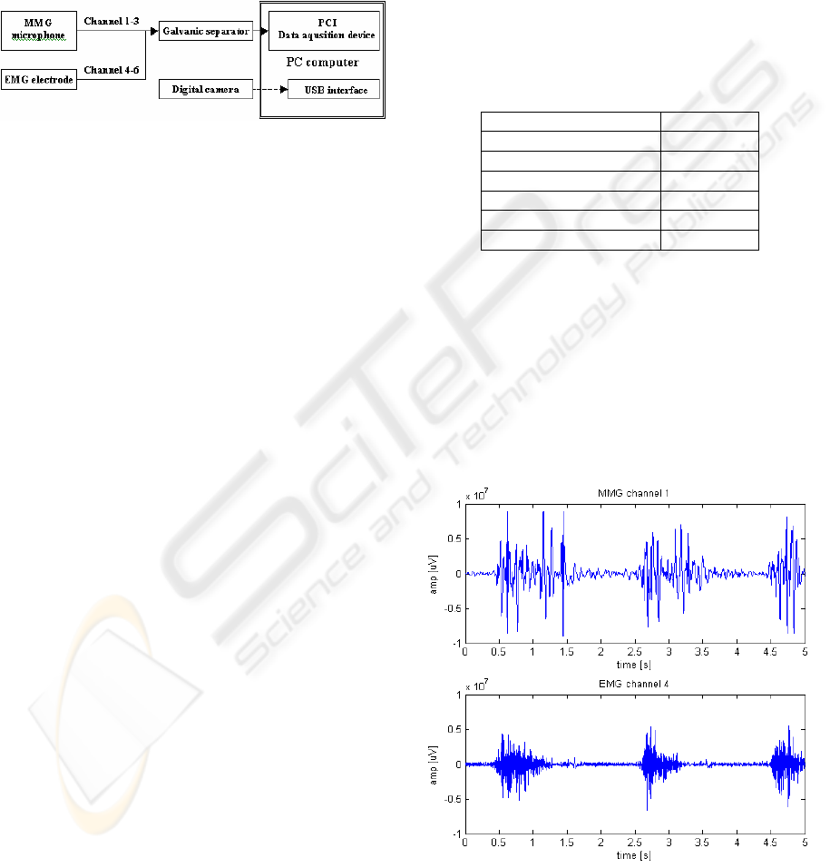
2 MEASUREMENT STAND
Measurement set was created specially for obtaining
signals from patients arm. The configuration used in
the measurement contained 6 input channels (Figure
1). Input channels from 1 to 3 were connected to the
microphone sensors and input channels from 4 to 6
were connected to EMG differential electrodes.
Figure 1: EMG and MMG acquisition system.
The microphone sensors are highly sensitive and
are situated in a heavy brazen housing separating it
from any external source of vibration. This
microphone situated on the skin surface, records
vibrations propagating in the tissue underneath it.
The microphone conditioning circuit filter out
frequencies above 150 Hz as the frequency range of
the mechanomyogram doesn’t shows frequencies
above this level (Orizio, C., 1993).
The EMG differential electrodes detect minimal
potentials occurring on the skin over working
muscles. It contains two contact poles situated 1 cm
away from each other and amplifies only the
difference between the two readings. Frequency of
the electromyogram goes into range between 20-400
Hz (Krysztoforski, K. and Wołczowski A., 2005).
A digital camera can be used as an addition to
the stand as feedback information. It allows
extracting data from specific stages of movement.
3 METHODOLOGY
In the experiment sensor were attached to the
patient’s right arm. One set of microphone and
electrode was positioned at the top of the forearm
near the elbow. The second and the third pairs of
microphone and electrode were positioned at the
bottom of the forearm near the elbow and near the
wrist, respectively. Table 1 shows the channels used
in the acquisition of EMG and MMG signals.
During the measurements patient was repeating
the same set of movements with various speeds and
duration of the muscle contraction. Those
movements were:
I – Hand closing;
II – Pointing with one finger;
III –Pointing with two fingers;
IV – Wrist flexion – down;
V – Wrist flexion – up;
VI – Pronation / suplination;
VII – Whole hand movement left / right;
All measurements were made with 1kHz probing
density and lasted 5 sec. In each 5 second
measurement the move was repeated two or three
times.
Table 1: Channels used in the acquisition systems.
Sensor Channel
MMG microphone 1
EMG electrode 4
MMG microphone 2
EMG electrode 5
MMG microphone 3
EMG electrode 6
3.1 Data Visualisation and Analysis
In order to create input for a classification system
the data gathered during the measurements had to be
analysed in search of the signal features. In figure 2
is shown typical MMG and EMG signals obtained
during 5 seconds in channel 4. It can be seen that
during these interval of time, one type of movement
was repeated three times during the presented tests.
Figure 2: EMG and MMG signals.
IDENTIFICATION OF HAND MOVEMENTS BASED ON MMG AND EMG SIGNALS
535
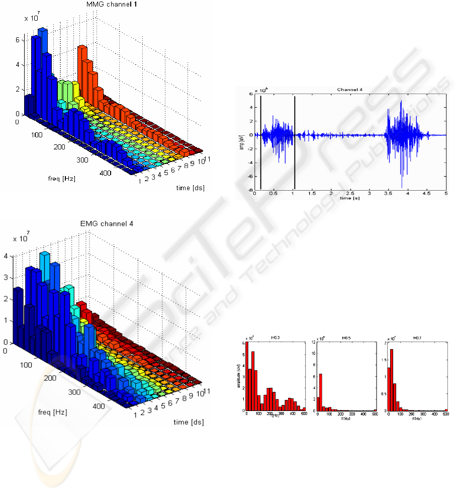
The signal features were observed on a 3D
histogram containing information in both time and
frequency domains using Short Time Fourier
Transform (STFT). An example of such histogram is
shown on figures 3 and 4, for MMG and EMG
signals obtained from one movement, respectively.
Figure 3: MMG frequency spectral density histogram.
Figure 4: EMG frequency spectral density histogram.
It can be deducted from the histograms analysis,
for every movement, that the MMG histogram has
two peeks – in the beginning and at the end of the
movement, whereas in the middle of the muscle
activation spectral density is relatively low.
In the EMG histogram the signal is strongest
while the muscle is kept contracted.
3.2 Feature Extraction
In the feature selection stage, the same number of
features for each EMG and MMG channel are used.
The selection of the elements of the feature input
vector has to take advantage of the knowledge about
the signal features in the time and frequency domain.
Therefore the selection of the input vector
elements is based on the time/frequency histograms.
The proposed algorithm for selecting points is
divided in five steps:
1- Extracting the movement part from every channel
of 5s measurement record (Figure 5);
Figure 5: EMG signal obtained in channel 4.
2- Application of the STFT in the beginning (0.3t,
where t is the movement time span), in the middle
(0.5 t) and at the end (0.7 t) of the extracted
movement;
3- In the frequency domain, in three specified
moments of time, a set of n points is obtained (from
the frequency range adequate to the channel type)
(Figure 6).
Figure 6: Frequency components in EMG signal.
4- Step 2 and 3 is repeated for every channel;
5- Normalization of the signals amplitude.
This procedure allows to create input vectors with an
adjustable size. The minimum number of elements
in the feature vector using 6 channels is 18. The
minimum structure of these feature vector used as an
input in the classifier based on a neural network is
given by:
BIOSIGNALS 2008 - International Conference on Bio-inspired Systems and Signal Processing
536
⎥
⎦
⎤
⎢
⎣
⎡
6
3
6
2
6
1
...
1
3
1
2
1
1
ch
ft
A
ch
ft
A
ch
ft
A
ch
ft
A
ch
ft
A
ch
ft
A
(1)
The element
1
1
ch
ft
A
represents the signal amplitude
in the channel 1 for the instant of time t1 in the
frequency f.
The minimum structure of the feature vector
using only three channels (EMG or MMG) as 9
elements and is given by:
[
]
3
3
3
2
3
1
1
3
1
2
1
1
...
ch
ft
ch
ft
ch
ft
ch
ft
ch
ft
ch
ft
AAAAAA
(2)
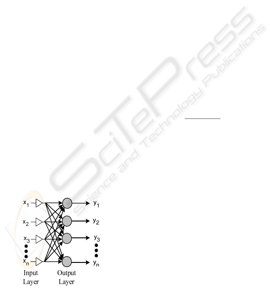
3.3 Classification Method
The electromyographic and mechanomyographic
signals are classified using the Learning Vector
Quantization (LVQ) neural network. The LVQ
network is a mutation of self-organizing Kohonen’s
maps. Unlike standard neural networks, it contains
usually only one layer of neurons. Each neuron is
subscribed to one class (Figure 7). The [x
1
, x
2
, …,
x
n
] is the feature vector and [y
1
, y
2
, …, y
n
] represents
each output movement. This kind of network proved
to be efficient in biosignal recognition problem in
previous research conducted by the authors
(Wolczowski A. 2001, Krysztoforski, K. and
Wołczowski A., 2005).
Usually there is more than one neuron for each
class. Each neuron has its weight vector containing
as many elements as data input (Kohonen, Teuvo K.,
1995). During the teaching of the network, in every
iteration, for each data vector a winning neuron is
being settled based on the closeness (in Euclid’s
metrics) of the neuron weights to the data vector
(Kohonen, Teuvo K., 1995).
Figure 7: Neural Network architecture.
If the winning neuron represents the same class
as the input vector, its weights are being changed to
be even closer to this input. If the classes are
different the weights are being pushed away.
The basic update algorithm is:
→ If x and m
c
represent the same class then
(
)
(
)
(
)() ()
[]
ttttt
ccc
mxmm −
+
=
+
α
1
(3)
→ if x and m
c
represent different classes then
(
)
(
)
(
)() ()
[]
ttttt
ccc
mxmm −
−
=
+
α
1
(4)
-> from i ≠ c,
(
)()
tt
ii
mm
=
+
1
(5)
where c is the index of the winning neuron and
(
)
t
α
is a teaching factor (
()
10 << t
α
).
There is a different teaching factor for each
neuron in the system and adapts during the process
of teaching, starting from the initial value of 0.5
according with the following expression:
()
(
)
() ( )
11
1
−+
−
=
tts
t
t
c
c
c
α
α
α
(6)
Where:
()
⎩
⎨
⎧
−
=
.,1
;,1
otherwise
correctistionclassificaif
ts
(7)
An algorithm for handling unused neurons in
every teaching epoch was applied.
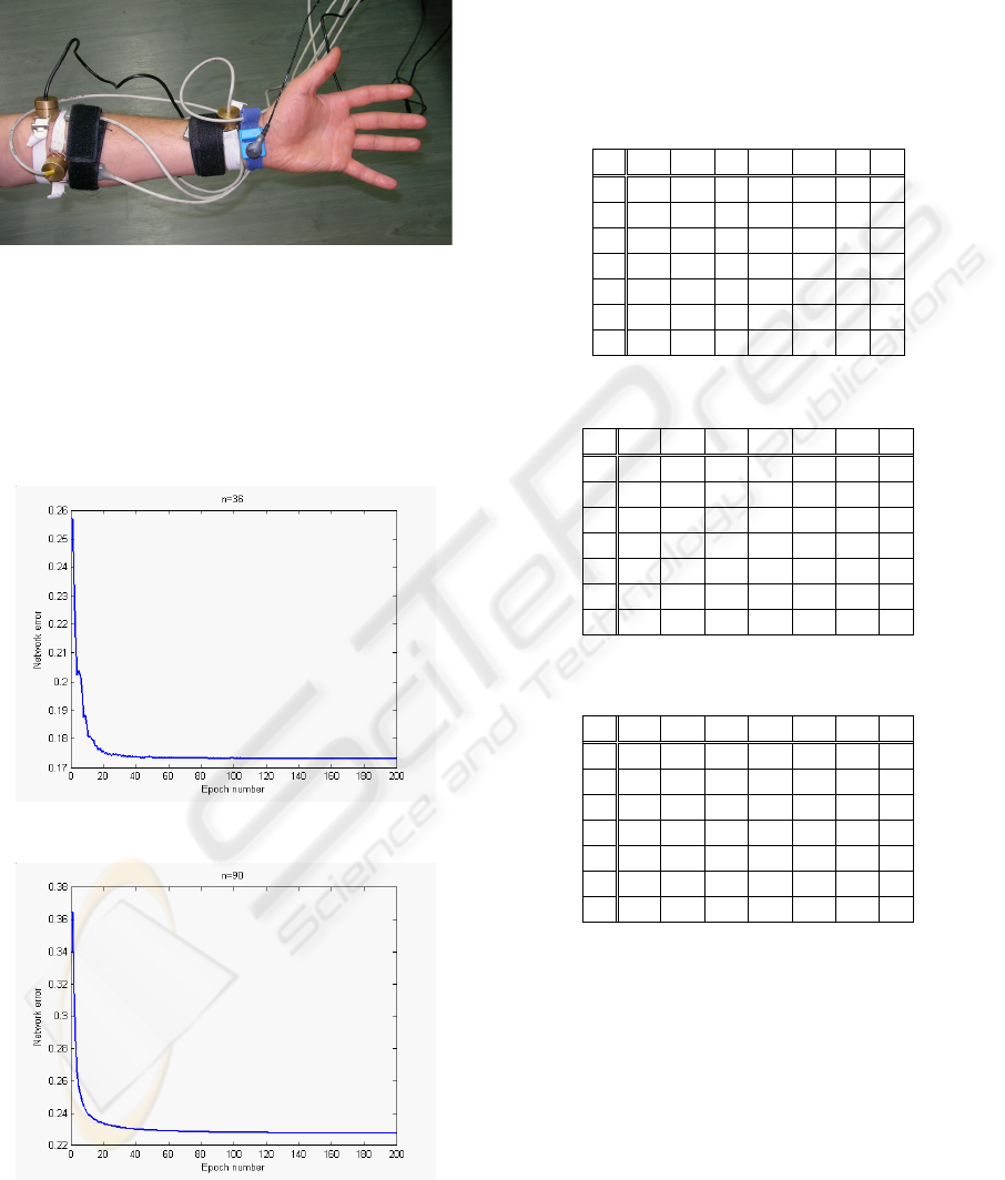
4 EXPERIMENTAL RESULTS
Experiments were carried out in laboratory, and
EMG and MMG signals were captured and recorded
simultaneously during the motion of the subject’s
hand (Figure 8). The next step was extracting the
features according to the proposed algorithm. Two
sets of vectors (containing 36 or 90 element) were
created. The vectors were divided into two groups –
one for teaching and the other for testing, each one
contained 81 vectors.
In each test the neural network was trained with
200 epochs using vectors from the teaching group.
Training was followed by the classification process
preformed on the vectors from the test group. The
same procedure was repeated using vectors based
IDENTIFICATION OF HAND MOVEMENTS BASED ON MMG AND EMG SIGNALS
537
only on EMG signal features and vectors based only
on MMG signal features in order to determine how
useful is the combination of both biomedical signals.
Figure 8: Patient's arm with attached sensors.
Figures 9 and 10, show the neural network error
during the training stage when the input vector size
is 36 and 90, respectively. The training error, for
each epoch, is obtained by the mean value of the
Euclidean distance between the current teaching
example and the winning neuron.
Figure 9: Training error for a vector size of 36.
Figure 10: Training error for a vector size of 90.
Tables 2-3 and Table 4, show the results of the
test vectors classification with the input vector size
of 18 and 36, respectively. In the first row of each
table it is represented the number of class movement
indicated by the classification process. In the first
column of each table are represented the class
movements of the examples introduced in to the
neural network. The test examples classified
correctly are in bold.
Table 2: Classification based on MMG signals.
1 2 3 4 5 6 7
1 10 0 2 0 0 0 0
2 2 13 3 0 0 0 0
3 0 0 8 0 1 0 0
4 0 0 0 10 0 0 0
5 0 0 0 0 11 0 3
6 0 0 0 0 0 8 1
7 1 0 0 0 0 2 6
Table 3: Classification based on EMG signals.
1 2 3 4 5 6 7
1 12 0 1 0 0 0 0
2 0 12 1 0 0 0 0
3 1 0 11 0 0 0 1
4 0 0 0 10 0 0 0
5 0 0 0 0 11 0 0
6 0 0 0 0 0 10 1
7 0 1 0 0 1 0 8
Table 4: Classification based on EMG and MMG signals.
1 2 3 4 5 6 7
1 12 0 1 0 0 0 0
2 0 13 1 0 0 0 0
3 1 0 11 0 0 0 0
4 0 0 0 10 0 0 0
5 0 0 0 0 11 0 0
6 0 0 0 0 0 10 1
7 0 0 0 0 1 0 9
The classification error obtained for the testing
vectors group using only information form MMG
channels was 18.52%. The error obtained using only
the EMG signals in the input feature vectors was
8.64%. Finally, when features from both the EMG
and MMG signals were used in the input vector, the
classification error decreased to 6.17%.
The same tests were done using an input vectors
with 45 and 90 elements. The results of the
classification process are shown in Tables 5-6 and
Table 7, respectively. The classification error
obtained using only MMG signal features was
24.7%. The error obtained using only the EMG
BIOSIGNALS 2008 - International Conference on Bio-inspired Systems and Signal Processing
538

signals in the input feature vector was 2.46%. When
it is combined in the input vector, the features from
both the EMG and MMG signals, the classification
error decreased to 1.24%.
Table 5: Classification based on MMG signals.
1 2 3 4 5 6 7
1 9 0 2 0 0 0 0
2 1 9 2 0 1 0 0
3 3 4 9 0 0 0 0
4 0 0 0 10 1 0 2
5 0 0 0 0 10 1 0
6 0 0 0 0 0 7 1
7 0 0 0 0 0 2 7
Table 6: Classification based on EMG signals.
1 2 3 4 5 6 7
1 13 0 1 0 0 0 0
2 0 13 0 0 0 0 0
3 0 0 12 0 0 0 1
4 0 0 0 10 0 0 0
5 0 0 0 0 12 0 0
6 0 0 0 0 0 10 0
7 0 0 0 0 0 0 9
Table 7: Classification based on MMG and EMG signals.
1 2 3 4 5 6 7
1 13 0 1 0 0 0 0
2 0 13 0 0 0 0 0
3 0 0 12 0 0 0 0
4 0 0 0 10 0 0 0
5 0 0 0 0 12 0 0
6 0 0 0 0 0 10 0
7 0 0 0 0 0 0 10
5 CONCLUSIONS
The results obtained during the experiment imply
that efficient identifying hand movements based
only on one MMG sensor is very difficult.
Especially the first three movements are being
confused during the identification process. The
reason for such error is because those movements
are caused by similar muscles and therefore sounds
propagating during those movements are much alike.
The EMG based identification system gives
much greater accuracy. The neural network taught
with EMG based data badly recognizes only a small
percent of test examples. Using the information
obtained from both mechanomyogram and
electromyogram improves results of the EMG-based
recognition. Therefore it can be concluded that the
mechanomyographic sensors can be used as a
enhancement to a EMG prosthesis system improving
the accuracy of identification and count of the
supported range of movements. LVQ network
proved produced sufficient and satisfactory
recognition ratio, therefore proving its usefulness in
the biosignal-based prosthesis control problem.
Further improvement could be achieved by applying
more complex neural network architectures in the
recognition process and also by modifying the
feature extraction algorithm. Those are the key
areas for future investigation of the problem.
REFERENCES
Orizio, C., 1993, Muscle sound: Bases for the introduction
of a Mechanomyographic signal in muscle studies,
Critical Reviews in Biomedical Engineering, 21(3),
pp. 201-243.
Asres, A., Dou, H. F., Zhou, Z. Y., Zhang, Y. L., Zhu, S.
C., 1996, A combination of AR and neural network
technique for EMG pattern identification, Proc. Ann.
Int. Conference IEEE Eng. Med. Biol. Soc., vol. 4, pp.
1464-1465.
Grossman, A., Silva, J., and Chau, T., 2004, Functional
Mapping of Multiple Mechanomyographic Signals to
Hand Kinematics, Canadian Conference on Electrical
and Computer Engineering, vol. 1, pp. 493-496.
Wołczowski, A., 2001, Smart Hand: The Concept of
Sensor based Control, Proc. of 7th IEEE Int. Symp. on
‘Methods and Models in Automation and Robotics’,
Międzyzdroje.
Goldenberg, M. S., Yack, H. J., Cerny F. J., and Burton,
H. W., 1991, Acoustic myography as an indicator of
force during sustained contractions of a small hand
muscle, J. Appl. Physiol., vol. 70, nº. 1, pp. 87-91.
Silva, J., Heim, W., and Chau, T., 2004, MMG-Based
Classification of Muscle Activity for Prosthesis
Control, Proc. 26
th
Annual Int. Conference of the
IEEE Engineering in Medicine and Biology Society,
vol. 2, pp. 968-971.
Tarata, M. T., 2003, Mechanomyography versus
Electromyography, in monitoring the muscular
fatigue, BioMedical Engineering Online, 2:3.
Ouamer, M., Boiteux, M., Petitjean, M., Travens, L., and
Sal’es, A., 1999, Acoustic myography during
voluntary isometric contraction reveals non-
propagative lateral vibrations, J. Biomech., vol. 32,
nº. 12, pp. 1279-1285.
Krysztoforski, K., Wołczowski A., 2005, Measurement
stand for recording EMG signals . Adv. of Robotics:
Industrial and medical robotic systems, WKL,
Warsaw.
Kohonen, Teuvo K., 1995, Self-Organizing Maps,
Springer, Berlin.
IDENTIFICATION OF HAND MOVEMENTS BASED ON MMG AND EMG SIGNALS
539
