
DSP IMPLEMENTATION AND PERFORMANCES EVALUATION
OF JPEG2000 WAVELET FILTERS
Ihsen Ben Hnia Gazzah, Chokri Souani and
Kamel Besbes
Laboratoire Microélectronique et Instrumentation
Faculté des sciences de Monastir
Keywords: Discrete wavelet transform, lifting scheme, filter banks, DSP.
Abstract: The lifting scheme wavelet Transform allows efficiency implementation improvement over filter banks
model. In this paper, we present simulation results and DSP implementation results of Lifting scheme
algorithm for 1D and 2D discrete wavelet transform (2D-DWT). The lossless and lossy wavelet filters 5/3
and 9/7, respectively, have been used to transform images. The transforms have been implemented in a
float-point DSP chip and performances are evaluated. The DSP code was optimized at source code level and
memory usage. The implemented code is optimized in different ways especially within memory usage.
1 INTRODUCTION
Since their introduction by Wim Sweldens in 1994
(Sweldens, 1996), the discrete lifting scheme (LS)
wavelet transform has gained widely acceptance due
to their ability to construct biorthogonal wavelets in
the spatial domain independently of the Fourier
transform (Daubechies et al., 1998; Chendonga et al.,
2007; Delouille et al., 2006). The lifting scheme
was adopted as the base of the JPEG 2000 standard
(Rabbani et al., 2002). The image compression in
the JPEG2000 standard is performed either by the
9/7 real values wavelet or by the 5/3 integer values
wavelet.
The DWT has been implemented conventionally
using the filter bank scheme (FBS). This solution
implements filters with convolution technique. It
requires both a large number of clock cycles and a
large amount of storage memory. However, the
lifting scheme requires less computations and less
storage memory space. Recent studies tempted to
compare between LS and FBS. In this context,
Gnavi (Gnavi et al., 2002) implemented both DWT
methods and compared their performances for image
coding task. He has found that the LS
implementation run faster than the filter bank
scheme. Special-purpose hardware is used to reduce
the execution time of the DWT, Programmable
processors, however, are preferable because they are
more flexible. Furthermore, multimedia SIMD
extensions (Shahbahrami et al., 2005) can be used to
reduce the execution time of the DWT.
In this paper, we present simulation results of
Lifting scheme algorithm using Matlab tool, and
implementation results using a TMS320C6713 DSP
processor. The code is optimized in order to reduce
the execution time while performing the
reconstruction quality. The lossless 5/3 and the lossy
9/7 lifting scheme transform were considered. The
paper presents our contribution on the 2D-DWT-LS
implementation into DSP processor. The paper is
organized as follows: In section 2, a background of
the lifting scheme is briefly explained, while an
overview of our experimental results is given in
section 3. Conclusions and future work are drawn in
the end.
2 LIFTING SCHEME
ALGORITHM
Lifting scheme decomposition consists on splitting
the original signal into two subsets defined by the
even and odd index signal samples, and then
gradually a new wavelet coefficients set is built
(Sweldens et al., 1996) (figure 1). The
decomposition is held in three steps:
• Split: This step is called “Lazy wavelet
Transform (LWT)”. It consists on decomposing the
410
Ben Hnia Gazzah I., Souani C. and Besbes K. (2008).
DSP IMPLEMENTATION AND PERFORMANCES EVALUATION OF JPEG2000 WAVELET FILTERS.
In Proceedings of the First International Conference on Bio-inspired Systems and Signal Processing, pages 410-415
DOI: 10.5220/0001067004100415
Copyright
c
SciTePress
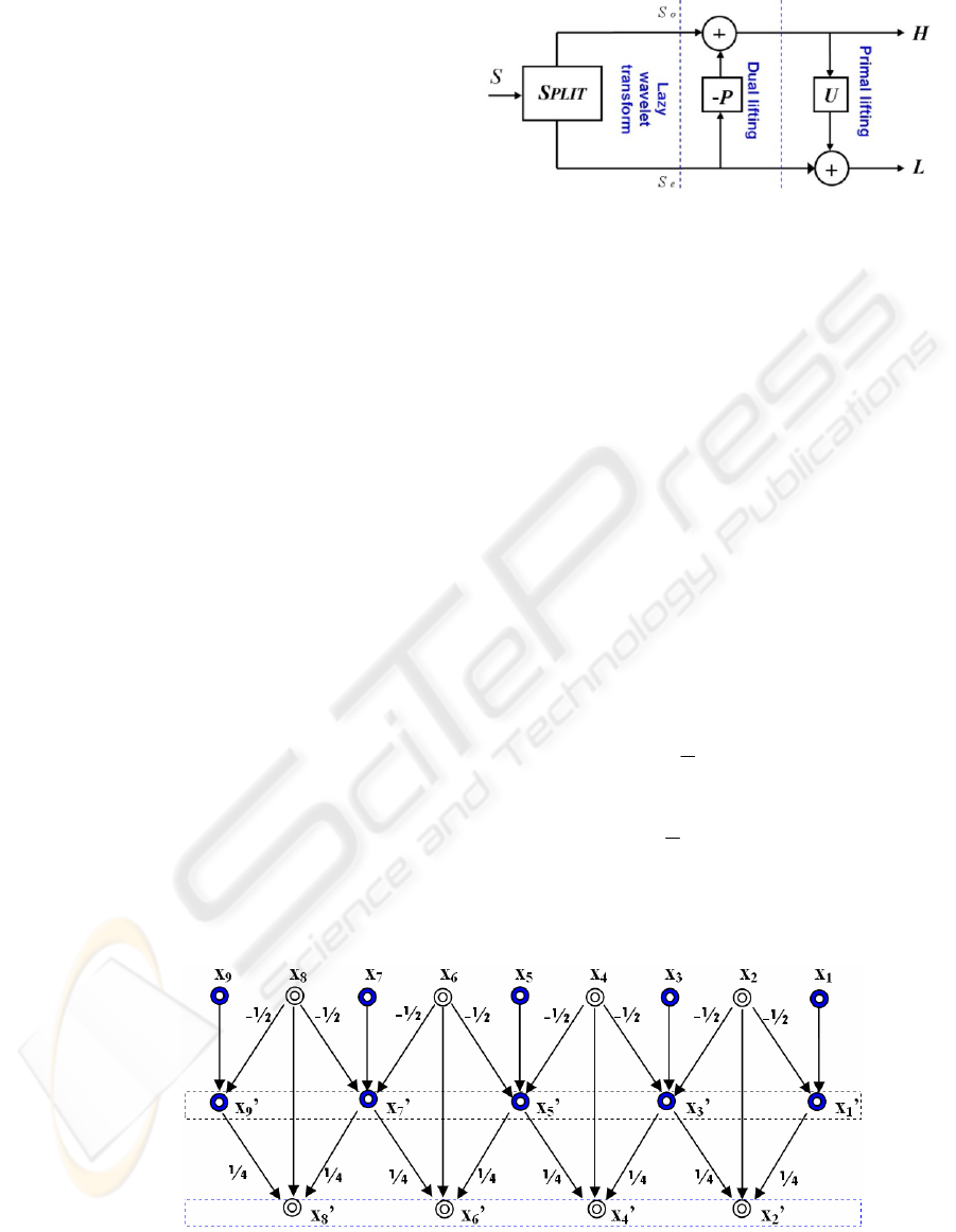
original image S into two sub-images. The two sub-
images are defined by the even (Se
i
=S
2i
) and the odd
(So
i
=S
2i+1
) pixel image coefficients. The LWT is a
simple function switching coefficients
corresponding to their order (odd or even).
Primal Lifting step: the original signal has
even and odd index samples interspersed. If the
signal has a local correlation structure, the even and
odd samples will be highly correlated. In other
words given one of the two sets, it should be
possible to predict the other set with reasonable
accuracy. The even set is always used to predict theo
dd one which represents the wavelet coefficients
(Daubechies et al., 1998).
i
H
are the wavelet
coefficients.
i
So
are the odd samples.
P
is the
prediction polynom and
i
Se
are even samples (eq. 1)
()
ii i
H
So P Se=−
(1)
Dual Lifting step: The update operator U is
applied to the wavelet coefficients computed
i
H
and then are addition with
i
Se
to compute
i
L
(eq.
2).
i
L
are the scaling coefficients.
()
ii i
L
Se U H=+
(2)
3 EXPERIMENTATIONS AND
RESULTS
In this section, we describe first the implementation
of the DWT using lifting scheme into a DSP
processor.
Figure 1: Basic structure of one dimensional Discrete
Wavelet transform (1D-DWT) using lifting scheme (Ben
Hnia Gazzah et al., 2007).
3.1 Implementation
The 5/3 filter allows achieving lossless image
compression and has short filter taps composed of
3/2 coefficients respectively to the 5 and 3 filter taps.
The 9/7 filter is composed of 5/4 taps respectively.
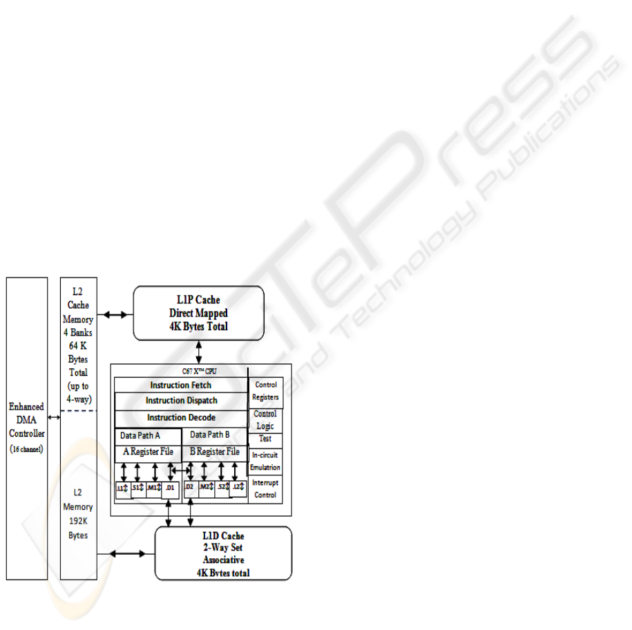
Figure2 shows the lifting scheme steps of the 5/3
wavelet filter. The Input samples
21k
x
+
and
2k
x
denote the odd and even samples, respectively,
resulting from the split step provided by the Lazy
Wavelet Transform (LWT). The prediction and
updating steps are given by
21k
x
+
′
and
2k
x
′
.
Coefficients
21k
x
+
′
and
2k
x
′
are the output
coefficients obtained by the prediction task and the
updating task respectively.
'
21 21 2 22
1
()
2
kk kk
xx xx
++ +
=− +
(3)
'''
22 2121
1
()
4
kk k k
xx x x
−+
=+ +
(4)
Figure 2: The lifting scheme set for 5/3 filter (Ben Hnia Gazzah et al., 2007).
Low-pass output
High-pass output
Input sample
Prediction
Update
DSP IMPLEMENTATION AND PERFORMANCES EVALUATION OF JPEG2000 WAVELET FILTERS
411
The 9/7 decomposition is computed within fou
r
steps (Daubechies et al., 1998) as shown
b
y
equation 5-8:
'
21 21 2 22
*( )
kk kk
xxaxx
++ +
=+ +
(5)
'''
22 2121
*( )
kk k k
xxbx x
−
+
=+ +
(6)
21 21 2 22
*( )
kk kk
xxcxx
++ +
′′ ′ ′ ′
=+ +
(7)
22 2121
*( )
kk k k
xxdx x
−
+
′′ ′ ′′ ′′
=+ +
(8)
The lifting coefficients (Jiang et al., 2005) are: a=-
1.5861, b=-0.0529, c=0.8829 and d=0.4435. The
high-pass coefficients
21k
x
+
′′
, are normalized by a
weight K
h
=1.2302, and the low pass coefficients
2k
x
′′
are normalized by K
l
=1/ K
h
.
The implementation is held with the Texas
Instrument TMS320C6713 floating-point processor.
The TMS320C6713 processor is a fast special-
purpose microprocessor with adequate architecture
(figure 3) for signal processing (Texas Instrument,
2002).
Figure 3: Functional bloc of TMS320C6713 and CPU
diagram (Texas Instrument, 2002).
The TMS320C6713 is based on the VLIW
architecture and its performance is rated at 1800
MIPS. The internal program memory is structured so
that a total of eight instructions can be fetched every
cycle. With a clock rate of 255 MHz the processor is
capable of fetching eight 32-bit instructions every
4.44ns (Texas Instrument, 2001).
It is used only one storage memory block, in the
algorithm description. In both prediction and update
stages a new computed coefficient replaces the
original input value without need to additional
emplacements (in place calculus). The inverse
transform is easily performed by inversing the steps
of LS and the operations signs.
3.2 Experimental Results
The implementation performances are evaluated in
term of execution time and cycle’s number per
computed pixel. Performance was measured using
the cycle counters (Texas Instrument, 2002). Cycle
counters provide a very precise tool for measuring
the time that elapses between two different points in
the execution of a program.
Obviously the execution
time depends on the image size (table1), the type of
used memory (internal or external memory) and the
number of steps of lifting scheme. The running time
when using processor internal memory is shorter
than that when using external memory. In our case,
due to the limited size of the internal memory (256
KB), we are conducted to use the external memory
(16 MB SDRAM) as a “buffer memory”.
Table1 shows the execution time ratio of external
memory to internal memory. The mean value ratio
for 5/3 filter is about “21”, however, the mean value
is about “39” for the 9/7 filter. The mean value for
9/7 filter is two times higher then that for the 5/3
filter: this is due to the number of lifting scheme
steps. The transforms with less lifting steps 5/3 tend
to perform better than transforms with more lifting
steps 9/7 in term of speed. In addition, we have
implemented the 5/3 lifting scheme using only
addition, subtraction, and shifting operations without
multiplications.
The code optimization by using internal memory
reduces the execution time. Obviously the internal
memory access time is lower than that of external
memory.
Figure 4 shows the running time using internal
memory and figure 5 shows the running time using
external memory.
BIOSIGNALS 2008 - International Conference on Bio-inspired Systems and Signal Processing
412
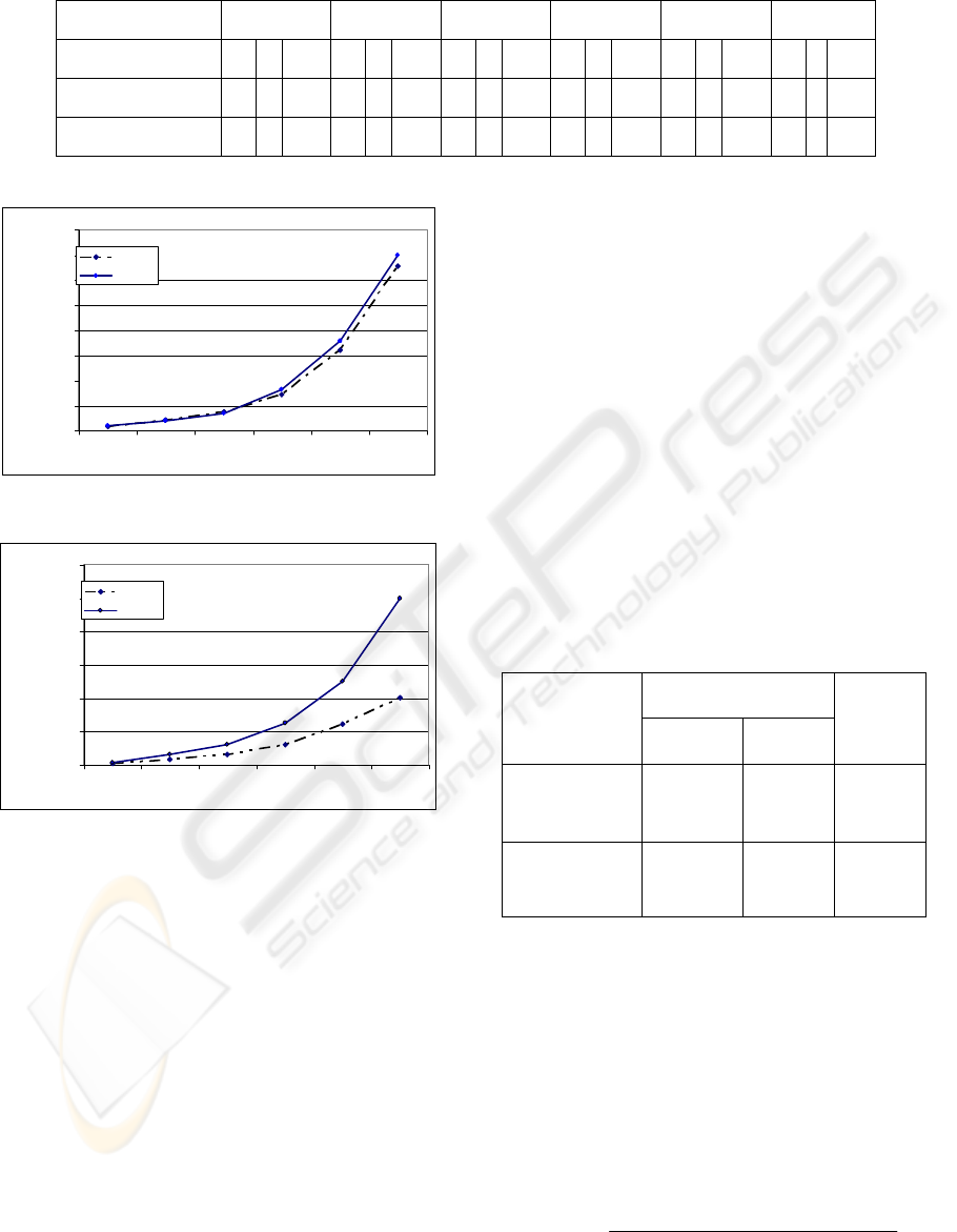
Table 1: Cycle’s number per pixel.
Samples number
64 256 512 1024 2048 4096
Memory type*
ext int Ratio ext int Ratio ext int Ratio ext int Ratio ext int Ratio ext in Ratio
5/3 filter
135 6 22.5 145 7 20.71 145 7 20.75 135 6 22.5 135 7 19.28 110 6 18.33
9/7 filter
274 7 39.14 273 7 39 274 7 39.14 275 7 39.28 275 7 39.28 275 7 39.29
*int = execution time of internal memory in cycles/pixel, ext = execution time of external memory in cycles/pixel
running time
0
20
40
60
80
100
120
140
160
64 256 512 1024 2048 4096
number of samples
time (microsecond
)
filter 5/3
filter 9/7
Figure 4: Running time using internal memory.
running time
0
1000
2000
3000
4000
5000
6000
64 256 512 1024 2048 4096
number of samples
time (microsecond
)
filter 5/3
filter 9/7
Figure 5: Running time using external memory (SDRAM).
Two sets of experiments of 1D- Discrete
Wavelet lifting implementation were performed: in
the first set, we used on-chip memory and external
memory. In the second set, we used only external
memory . Two programs have been implemented.
They differ in the processing part. In the first
program, the processing took place in the internal
memory (on-chip memory), however in the second
program, the processing part of the C-program is
held in the external memory.
Execution time results (cycles/pixel) for both
methods of the 1D- Discrete Wavelet lifting are
shown in Table 2. The comparison of the execution
time between both methods shows that the one using
internal memory is about three times faster than the
other using external memory SDRAM 16MB for the
filtering operation.
We optimize the execution time of the lifting
scheme by using internal memory for processing in
three steps:
First, the image is divided into several blocks
before storage into the SDRAM memory. Secondly,
the blocs are transferred in the L2 cache internal
memory. The filtering operation is performed by the
lifting scheme algorithm. Finally the transformed
image is transferred to the external memory
(SDRAM) for result storage.
Similarly, the next blocks of image are transferred
one after another into L2 cache where they are
processed. The number of blocks depends on the
image size. In the case of 256x256 image size, the
size of each block is 64x256 pixels. Four successive
blocks are to be used.
Table 2: Execution time of the 1D- Discrete Wavelet
lifting for image (Baboon 256x256) using 5/3 filter.
Execution time
(Cycles/pixel)
Execution
time A*
Execution
time B**
Ratio of B
to A
image(256*256
pixels)
decomposition
43 135 3.14
image (256*256
pixels)
reconstruction
43 134 3.16
*A : execution time using internal memory for processing.
**B : execution time using external memory for processing
(SDRAM).
The reconstructed image was compared to the
original image and the peak signal-to-noise ratio
(PSNR) in decibels was computed for images to
evaluate the performance of the wavelet lifting
scheme transform program. In the case of an image
whose intensity of the pixels lies between 0 and 255,
the PSNR is given by the following formula:
[]
2
10
2
11
255
10.log ( )
1/( . ) . ( ( , ) ( , ))
MN
ij
P
SNR dB
MN xi j xi j
==
=
−
∑∑
%
DSP IMPLEMENTATION AND PERFORMANCES EVALUATION OF JPEG2000 WAVELET FILTERS
413
where: M×N is image size computed in pixels
: (1<i<M) and (1<j<N) denote pixel indices.
We have founded a higher PSNR for wavelet
lifting scheme transforms. This verifies a perfect
reconstruction property of Wavelet lifting scheme
transform. Table3 shows the PSNR and SNR results
obtained by DSP implementation and MATLAB
simulation using 2D wavelet lifting scheme
transform for both 5, 3 and 9, 7 filters.
The 2-D discrete wavelet transform (DWT)
based on a lifting scheme, is carried out as a
separable transform by cascading two 1-D
transforms in the horizontal and vertical direction.
Each level of wavelet decomposition provides four
sub-bands of decomposition images: LL, LH, HL
and HH with halved resolution in both horizontal
and vertical directions.
In our application we implemented the 2D-DWT
on DSP using Lifting scheme until level three with
different image sizes: Barbara (512x512),
Cameraman (256x256), Lena (256x256), Baboon
(512x512), goldhill (512x512), lena(512x512).
The same algorithm was simulated using
Matlab language. We compared PSNR results of 2D
lifting scheme at level three using different image
sizes (table .3). Experimental and simulation results
have almost the same performance.
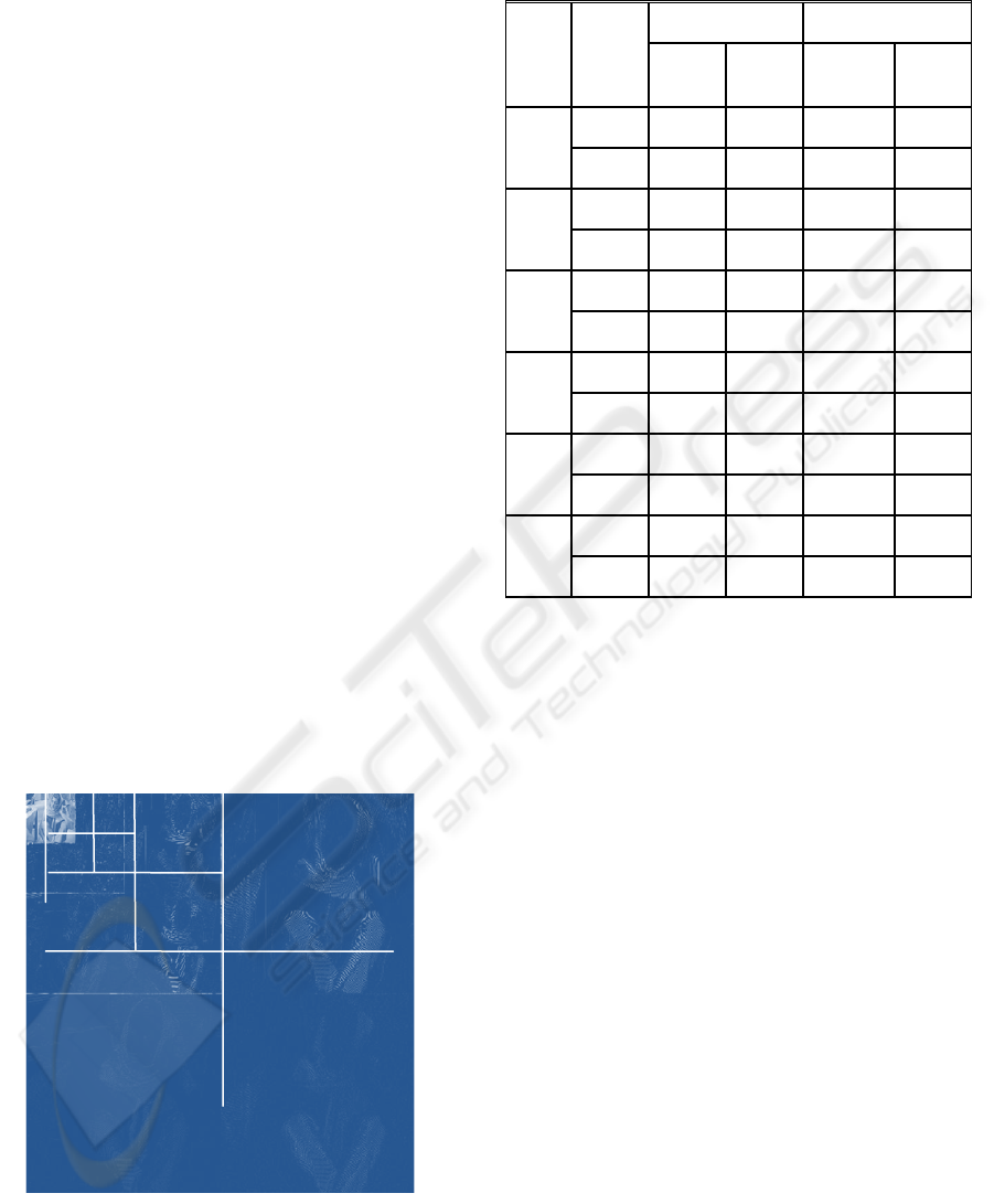
The following figure represents three levels of the
2D-DWT with Lifting implemented on DSP using
Barbara image (512 x 512 pixels).
Figure 6: 3-level 2D-DWT using lifting scheme with
Barbara image 512x512 pixels.
Table 3: PSNR results of 2D lifting scheme
implementation and MATLAB simulation (level three).
Wavelet CDF9/7 Wavelet LeGaull 5/3
image
Perfor-
mance Simulation
results
Experiment
al
results
Experimental
results
Simulation
results
PSNR (dB)
307.929 ∞ ∞ ∞
Barbara
512*512
SNR
301.522 ∞ ∞ ∞
PSNR (dB)
307.016 ∞ ∞ ∞
Baboon
512*512
SNR
301.550 ∞ ∞ ∞
PSNR (dB)
307.171 ∞ ∞ ∞
lena
512*512
SNR
301.514 ∞ ∞ ∞
PSNR (dB)
307.452 ∞ ∞ ∞
lena
256*256
SNR
301.647 ∞ ∞ ∞
PSNR (dB)
307.114 ∞ ∞ ∞
Camera-
man
256*256
SNR
301.532 ∞ ∞ ∞
PSNR(dB)
307.979 ∞ ∞ ∞
Goldhill
512*512
SNR
301.613 ∞ ∞ ∞
4 CONCLUSIONS AND FUTURE
WORK
In this paper, we reported the implementation of 2D-
DWT using lifting scheme algorithm on the
TMS320C6713 DSP, floating-point processor. We
used 5/3 and 9/7 filters. We compared the
implementation of the algorithm on DSP with the
simulation using Matlab.
For both methods, we obtained high PSNR
values of different images sizes confirming efficacy
of the approach. The most important advantages of
the lifting scheme (Ben Hnia Gazzah et al., 2007)
for wavelet transform were verified which are:
perfect reconstruction capability, in place
computation.
We optimized speed execution time of DSP
implementation of lifting scheme algorithm in
different ways especially within memory usage.
Execution times of the two algorithms of 5/3 and
9/7 filters on a DSP have been compared. The
corresponding C-program for a 1-level 1D DWT of
5/3 filter is up to 3x faster than of the 9/7. Integer to-
integer transforms are often faster than real-to-real
transforms, because the 5/3 wavelet filter requires
BIOSIGNALS 2008 - International Conference on Bio-inspired Systems and Signal Processing
414

two lifting scheme steps, however the 9/7 wavelet
filter requires four ones.
The future work will be optimizing speed
execution time of lifting scheme algorithm using
DMA.
REFERENCES
Ben Hnia Gazzah, I., Souani, C., and Besbes, K., 2007,
“DSP implementation of lifting Scheme transform”,
Journées scientifiques des jeunes chercheurs en Génie
Electrique et Informatique, pp 445-451.
Chendonga, D., Zhengjiab, H., and Hongkai, J., 2007, A
sliding window feature extraction method for rotating
machinery based on the lifting scheme, Journal of
Sound and Vibration, vol. 299, pp 774–785.
Daubechies, I., and Sweldens, W., 1998, “Factoring
wavelet transforms into lifting steps,” Journal of
Fourier Analysis and Applications, vol. 4, pp. 245–
267.
Delouille, V., Jansen, M., and Von Sachs, R., 2006,
Second-generation wavelet denoising methods for
irregularly spaced data in two dimensions, Signal
Processing, vol. 86, pp 1435–1450.
Gnavi, S., Penna, B., Grangetto, M., Magli, E., and Olmo,
G., 2002, Wavelet Kernels on a DSP: A Comparison
Between Lifting and Filter Banks for image Coding,
EURASIP Journal on Applied Signal Processing,
Hindawi Publishing Corporation: 9, 981–989.
Jiang, K., Dubois, E., 2005, Lifted wavelet-based image
dataset compression with column random access for
image-based virtual environment navigation, IEEE
International Workshop on Haptic Audio Visual
Environments and their Applications, Ottawa, Ontario,
Canada.
Rabbani, M., and Josi, R., 2002, An Overviewof the the
JPEG2000 Still Image Compression Standard Signal
Processing: Image Communication, 17(1), pp.3-48.
Shahbahrami, A., Juurlink, B., and Vassiliadis, S., 2005
Performance Comparison of SIMD Implementations
of the Discrete Wavelet Transform, Proc. 16th IEEE
Int. Conf. on Application-Specific Systems
Architectures and Processors (ASAP), Samos, Greece,
July 23-25.
Sweldens, W., 1996, Wavelets and the lifting scheme, A 5
minute tour, Zeitschrift für Angewandte Mathematik
und Mechanik, vol. 76 (Suppl. 2), pp. 41-44.
Sweldens, W., and Schröder, 1996, Building your own
wavelets at home, in Wavelets in Computer Graphics,
ACM SIGGRAPH course notes, pp. 15-87.
Texas Instrument, Revised November 2002,
TMS320C6713 Floating-Point Digital Signal
Processor, Datasheet SPRS186B
Texas Instrument, december 2001, TMS320C6713
Floating-Point Digital Signal Processor, Datasheet
SPRS186L.
DSP IMPLEMENTATION AND PERFORMANCES EVALUATION OF JPEG2000 WAVELET FILTERS
415
