
AN FPGA PLATFORM FOR REAL-TIME SIMULATION OF
TISSUE DEFORMATION
Samson Ajagunmo and Aleksandar Jeremic
Department of Electrical and Computer Engineering, Main St., Hamilton, Ontario, Canada
Keywords: Reconfigurable Architecture, Tissue deformation, Matrix-by-Vector Multiplication, Conjugate Gradient
Method, Field Programmable Gate Arrays.
Abstract: The simulation of soft tissue deformations has many practical uses in the medical field such as diagnosing
medical conditions, training medical professionals and surgical planning. While there are many good
computational models that are used in these simulations, carrying out the simulations is time consuming
especially for large systems. In order to improve the performance of these simulators, field-programmable-
gate-arrays (FPGA) based accelerators for carrying out Matrix-by-Vector multiplications (MVM), the core
operation required for simulation, have been proposed recently. A better approach, yet, is to implement a
full accelerator for carrying out all operations required for simulation on FPGA. In this paper we propose an
FPGA accelerator tested for simulating soft-tissue deformation using finite-difference approximation of
elastodynamics equations and conjugate-gradient inversion of sparse matrices. The resource and timing
requirements show that this approach can achieve speeds capable of carrying out real-time simulation.
1 INTRODUCTION
Some of the most common procedures in clinical
practice (e.g. the insertion of subcutaneous needles
in the tissue for biopsy of deep-seated tumors) are
extremely sensitive to guiding algorithms and initial
placement of the needle. One of the current trends in
this field is the development of virtual simulators for
tissue deformation. Realistic simulation of tissue
deformation undergoing needle insertion is the
bottleneck of all virtual simulators.
The deformation of soft tissue is determined by
elastodynamic partial differential equations (PDEs)
(Fung, 1987), defined over irregular domains
(human organs). A solution to these PDEs cannot be
obtained analytically due to their nonlinearity and
irregular shape of the domain. In order to solve
these equations we need one of commonly used
discretizaion techniques: the finite-difference
method (FDM) and the finite-element method
(FEM). In both methods, the domain of interest is
discretized and the corresponding PDEs are
transformed into linear equations. The resulting
linear system is then solved using numerical
methods such as Newtons method, conjugate-
gradient method (CGM) etc.
Most of the resent work done in this area focused
on speeding up numerical methods by implementing
efficient matrix-by-vector multiplier units (MVU) on
FPGA. In (Ramachandran, 1998) the author
investigated the performance effects of using an
FPGA based MVU to carry out an MVM. The MVU
was able to achieve a performance of 36 MFLOPS
with a matrix generated using the Finite-Element
method. In (Zhuo et. Al, 2005) the authors also
developed an MVU for MVMs that involved sparse
matrices. Their method involved using only the non-
zero elements of a matrix to carry an MVM. The
design in (Zhuo et al, 2005) attained a performance
of 350 MFLOPS for all their test cases. This is a
900% increase in performance when compared with
results in (Ramachandran, 1998). Note however, that
as of 2005, FPGAs were capable of higher clock
frequencies than in 1998, which most likely was one
of rather important factors for such improvement.
In this paper we propose an FPGA platform for
real-time simulation of tissue deformation using
FDM model and CGM for solving the corresponding
linear system. We will implement the CGM, a full
numerical method, in hardware on an FPGA. We
will also exploit the fact that the “stiffness” matrix is
sparse and band-limited. Our preliminary results
indicate that we can achieve sufficiently high
computational rate even with larger size meshes.
302
Ajagunmo S. and Jeremic A. (2008).
AN FPGA PLATFORM FOR REAL-TIME SIMULATION OF TISSUE DEFORMATION.
In Proceedings of the First International Conference on Bio-inspired Systems and Signal Processing, pages 302-306
DOI: 10.5220/0001069903020306
Copyright
c
SciTePress
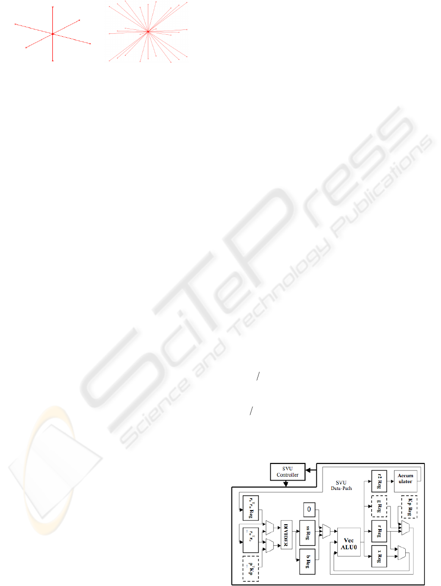
2 BACKGROUND
A B
Figure 1: Connection Pattern Models.
We model the soft tissue as a three-dimensional grid
of uniformly distributed nodes (material points)
connected together by springs that model the elastic
properties of the tissue. To model the connection
between two material points we use two connection
patterns shown in Figure 1. Using a quasi-static
approach when an external force acts on a certain
node, it causes a change in the length of the springs
connected to that node. This also creates opposing
forces in these springs so as to keep the system of
connected springs in equilibrium. This relationship,
for a given direction d at a node i,j,k, is given in (1)
by the function
f
i, j,k
d
.
111
,, , ,
111
ddd
ijk ilj mk n
nml
fku
++ +
=− =− =−
=
∑∑∑
(1)
Assembling these nodal equations for every node
yields a set of linear simultaneous equation that
describes the system in direction
d . These equations
can be represented in matrix form as shown in (2),
where
d,K
d
, f
d
are the displacement vector,
dd
fKd= (2)
characteristic (“stiffness”) matrix, and load vector
respectively, in the direction of
d . To solve the
equation in (2), for each direction
d , we utilize the
CGM, which is an iterative technique that can be
carried out amenably on FPGA at speeds capable of
real-time simulations.
3 CGM ACCELERATION
The CGM consists of a series of one or more MVM
and vector-by-vector multiplication (VVM). Since
MVMs are more computationally intensive than
VVMs, the effective bottleneck of this numerical
method are the MVMs. The acceleration of the
CGM involves designing hardware optimised for
carrying out operations needed by the CGM (CGM
Accelerator), and the speeding up of MVMs.
Speeding up MVMs involves dividing the
multiplying matrix
K and vector v into smaller
appropriately dimensioned sub-matrices and sub-
vectors. Each of these sub-matrices and sub-vectors
are then used by a series of MVUs working in
parallel, to carry out the required MVM. Each of
these sub-matrices must be stored in separate
memory blocks, one for each of the MVUs that will
be working in parallel.
The CGM accelerator consists of a series of
MVU for carrying out MVMs, and a Scalar-Vector
Unit (SVU) for carrying out the remaining scalar
and vector operations in the CGM.
3.1 SVU Design
As mentioned earlier, the SVU carries out all the
required operations in the CGM except for the
MVM. In Figure 2, we show the set-up that carries
out these operations. Most of the operations in the
CGMs main loop (shown below) are dependent on
each other hence; they must be carried out
sequentially in the order of dependence. For
example α must be updated before x or r is updated,
and r must be updated before β is updated. The
updating of x and r are, however, independent of one
another, so they can be carried out simultaneously.
However,
the amount of time, one clock cycle, that
is saved is not justified when considering that the
Result Final
direction Search New Calculate *
for Size Step New Calculate
Residual New Calculate *
New Calculate *
and for Size Step New Calculate
1
:1for
Direction Initial
guess initialon basederror Residual
0
1
11
11
11
1111
00
n
nnn
n
T
nn
T
n
nnn
nnn
n
T
nn
T
n
nn
n
xx
end
pprp
prrrr
rKprr
xpxx
rxKpprr
nn
Nn
rp
xxKxbr
n
=
+=
=
−=
+=
=
+=
=
=
=−=
=
−
−−
−−
−−
−−−−
β
β
α
α
α
Figure 2: SVU Design.
AN FPGA PLATFORM FOR REAL-TIME SIMULATION OF TISSUE DEFORMATION
303
amount of resources that is required to update x and
r will be doubled. However, we can double the size
of the system that the SVU can handle by allowing
an extra clock cycle. The completion time for the
SVU is always fixed, unlike the MVU were the
completion time will vary with the size of the matrix
that it uses for the MVM.
As seen in Figure 2, the three main modules used
in the SVU data-path are a Divider, a Vector ALU
(VecALU), and an Accumulator. The operations
performed by these modules are described next.
Divider:
This module is used to calculate α and β,
which are used by VecALU.
VecALU:
This is an arithmetic logic unit (ALU)
that specifically carries out vector-vector or vector-
scalar operations. The residual r, search direction g,
and deformation x are updated here. The module
uses previous values along with α and β to generate
new values. The new value of r is passed to the
Accumulator.
Accumulator: This module basically sums the
elements of the register r2 reg. The result of this
summation is the 2-norm of vector r. Hence, each
element of register r2 Reg is the square of the
corresponding element in r. The divider uses this 2-
norm value in the calculation of α and β.
The SVU-Control controls the flow of
information among the registers and modules in the
SVUs data-path. As seen in Figure 2, there are three
registers, shown by dashed lines, one for the
multiplying vector, while the others are for the MVU
results. These are the three registers used to pass
information between the SVU and the MVU. The
multiplying vector
register g Reg is used for passing
the direction vector to the MVU, while the result
registers,
p
T
Kp Reg and Kp
Reg, are used for
receiving the MVU results (p
T
Kp and Kp).
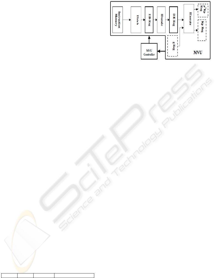
3.2 MVU Design
This MVU is designed specifically for MVMs, of
the form Kp and p
T
Kp, which may involve sparse
matrices. The design, shown in Figure 3, requires
only the non-zero elements of the matrix to be stored
in the memory. The non-zero elements are stored in
memory as part of a simple 32-bit instruction format,
shown below, that was designed for the MVU.
Further, these non-zero elements are stored in
memory using fixed-point format.
a(1bit) b(1bit) c(9bits) d(21bits)
a 1
st
bit determine s end of matrix.
b 2
nd
bit determine s end of row.
c 3
rd
to 11
th
bits used to determine the column of
the nonzero value.
d last 21 bits give the nonzero value.
Figure 3: MVU Design.
The MVU data-path is pipelined and divided into
three modules, namely, Instruction Fetch module
(IFetch), Instruction Decode module (IDecode), and
Execute module (IExecute).
IFetch: This module just fetch’s the next instruction
from memory and forwards it to IDecode for use.
The instructions are read sequentially with the
addresses gotten from a sequential counter.
IDecode:
The instruction is decoded here using the
format described earlier. It is determined here if the
end of the current row or column (ERC) or the end
of matrix (EM) has been reached. The address of the
next vector element needed for the next
multiplication is also determined here.
IExecute:
This module basically performs the
traditional MVM (i.e. taking the inner product of
each row and the multiplying vector, starting with
the first row) using a set of multipliers and
accumulators. The calculation of p
T
Kp and Kp are
done concurrently, with the appropriate values
stored in the appropriate result registers.
The MVU-Controller controls the flow of
information among the registers and modules in the
MVU data-path. As discussed earlier, the MVU
result registers, and multiplying vector register are
used for passing information between the SVU and
MVU.
4 RESOURCE USAGE AND
PERFORMANCE
FPGAs contain three main resources namely,
multipliers, logic elements and registers. Of these
three, the multipliers are of least abundance. This
makes them the bottleneck of any design for
applications that are heavily dependent on the usage
of multipliers. For this reason, we use the multiplier
usage as the primary measure of our designs
resource usage, as it is the deciding factor in the
maximum size of the system that can be solved on
BIOSIGNALS 2008 - International Conference on Bio-inspired Systems and Signal Processing
304
one FPGA. Figure 4 shows the multiplier usage of
our CGM accelerator implementation for different
number of MVUs and problem sizes n (number of
nodes). We implemented the CGM accelerator on
Altera’s DE2 development board using the Quartus
II development software. The implementation can be
clocked at speeds up to 133MHz.
The completion time for one iteration of the
CGM is given by (5), the sum of the completion
times for the SVU and MVU. Of these two,
T
MVU
M
VU SVU
TT T=+ (3)
is the only time that can be improved on by using the
technique described in section 3. Minimizing
T
MVU
effectively reduces the to time to carry out the CGM.
Hence
T
is a good measure of performance for our
CGM accelerator. We used a two-pronged approach
to test for the timing performance of the CGM
accelerator. Firstly, we used Quartus II simulator to
get preliminary test results for the CGM accelerator.
Secondly, we will verify these simulation results
with test results from the hardware implementation
of the CGM accelerator. These tests are done at
100MHz. In Figure 5 we show the preliminary
results for the computation time,
T
, of one iteration
of the CGM as a function of number of MVUs and
problem size n.
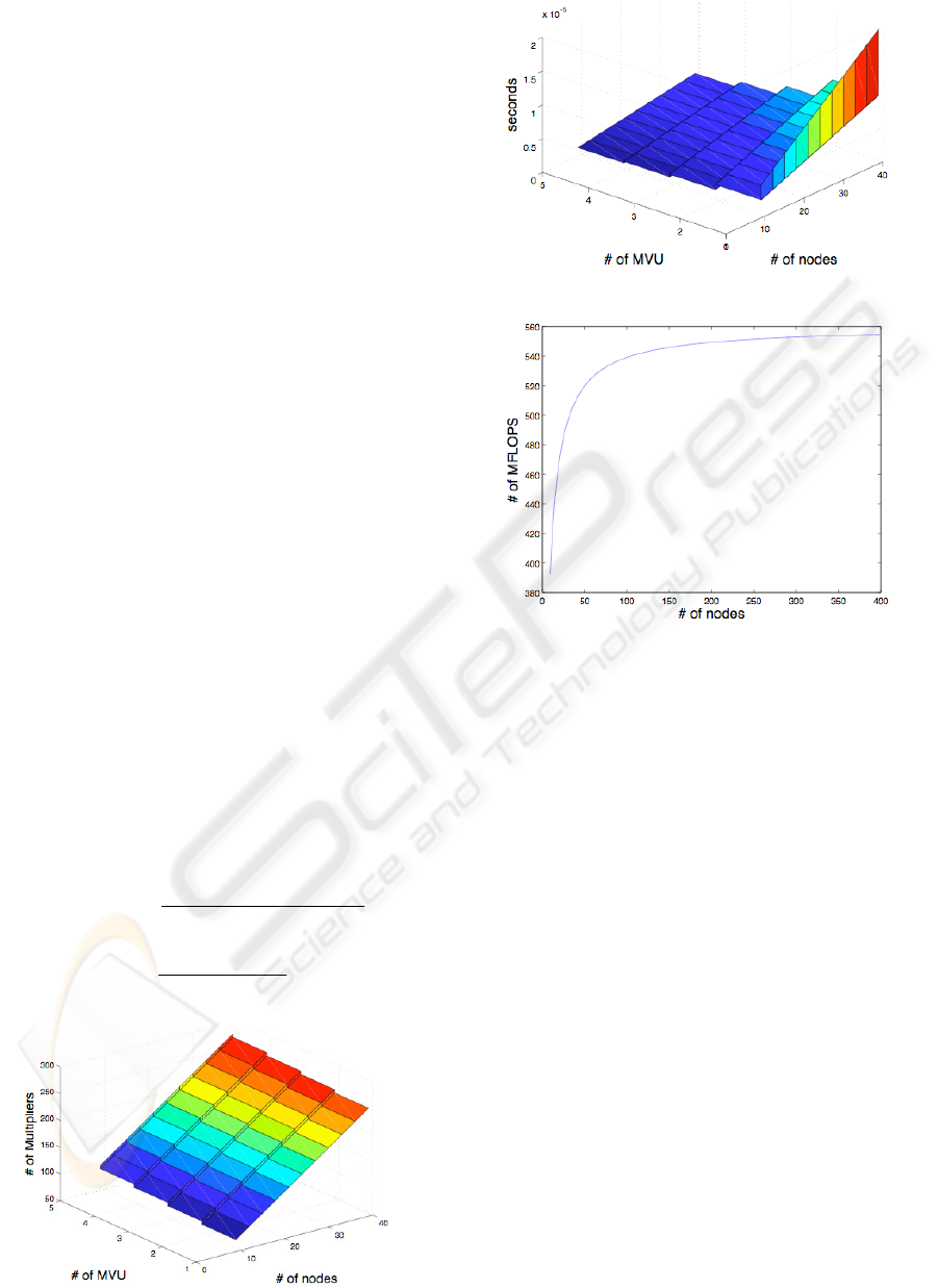
MFLOPS, given by (4), is another common
measure of performance. MFLOPS is a measure of
the number of floating point operations per second.
n is the size of the problem and m is the of average
number of nonzero elements per row. In Figure 6,
we show the MFLOPS performance as a function of
problem size for systems generated using connection
pattern B in Figure 1. Our CGM accelerator was
# / .
/.
232
Total of flops iter
MFLOPS
compute time iter
mn n
T
=
++
=
(4)
Figure 4: Multiplier Usage.
Figure 5: Computation time.
Figure 6: MFLOPS Performance.
able to achieve more than 540 MFLOPS with 5
MVUs working in parallel. As you can see in Figure
6, the performance of the system plateaus as n gets
larger. This is mainly due to the fact that the number
of MVUs is fixed. However, for better performance,
we can use more MVUs in parallel. Note, however,
that the use of more than one MVU in parallel
means that fewer multipliers are available for use by
the SVU, as the number of multipliers available on
the FPGA is fixed. Hence, the amount of resources
available determines the optimal number of MVUs
that can be used in parallel, and size of problems that
can be solved.
5 CONCLUSIONS
We proposed and implemented an FPGA based
CGM accelerator for carrying out real-time
simulation of tissue deformation. Our design does
not require any information on the sparsity of the
stiffness matrix. Further more, we gave a brief
discussion on improving the speed of MVMs using
parallel computing. We then looked at the resource
requirements and the performance of the CGM
accelerator. Our preliminary performance results
AN FPGA PLATFORM FOR REAL-TIME SIMULATION OF TISSUE DEFORMATION
305

show that developing FPGA accelerators for use in
real-time simulation is feasible. Our next step is to
verify these results as described in section 4.
REFERENCES
Chapra, C. S., Canale, P. R., 2002. Numerical Methods for
Engineers, McGraw Hill. NewYork, NY, 4
th
edition.
DiMaio, S. P., Salcudean , S. E., 2002. Needle Insertion
Modelling for the Interactive Simulation of
Percutaneous Procedures. In the 5
th
International
Conference on Medical Image Computing and
Computer-Assisted Intervention-Part II. Springer-
Verlag 253-260.
Fung, Y.C., 1987, Biomechanics, Springer-Verlag, New
York.
Goulb, H. G., Van Loan, F. C., 1996. Matrix
Computations, The John Hopkins University Press.
London, 3
rd
edition.
He, C., Qin, G., Zhao, W. FPGA-Based High-Order Finite
Difference Method for Linear Wave Modelling
Problems. Retrieved June 11, 2006, from
http://lacsi.rice.edu/symposium/symposumdownloads.
Hennessy, L. J., Patterson, A. D., 2003. Computer
Architecture: A Quatitative Approach, Morgan
Kaufmann Publishers. San Francisco, CA, 3
rd
edition.
Ramachandran, K., 1998. Unstructured Finite Element
Computations on Configurable Computers.
Blacksburg, Virginia: University Libraries, Virginia
Polytechnic Institute and State University.
Rocha, K. M. C. Numerical Techniques for Real Options.
Retrieved May 15, 2006, from
http://www.puc-rio.br/marco.ind/katia-num.html.
Zhuo, L., Prasanna, V. K., 2005. Sparse Matrix-Vector
Multiplication on FPGAs. In Computation algorithms
for FPGA, ACM/SIGDA 13
th
international symposium
on Field programmable gate arrays. ACM Press. 63-
74.
Altera DE2 Development Board
http://www.altera.com/education/univ/materials/board
s/unv-de2-board.html.
BIOSIGNALS 2008 - International Conference on Bio-inspired Systems and Signal Processing
306
