
A FAST POST-PROCESSING TECHNIQUE FOR REAL-TIME
STEREO CORRESPONDENCE
Georgios - Tsampikos Michailidis, Leonidas Kotoulas and Ioannis Andreadis
Democritus University of Thrace, Department of Electrical and Computer Engineering, GR-67 100 Xanthi, Greece
Keywords: Stereo vision, real time, disparity maps.
Abstract: In computer vision, the extraction of dense and accurate disparity maps is a computationally expensive and
challenging problem, and high quality results typically require from several seconds to several minutes to be
obtained. In this paper, we present a new post-processing technique, which detects the incorrect
reconstructed pixels after the initial matching process and replaces them with correct disparity values.
Experimental results with Middlebury data sets show that our approach can process images of up to
3MPixels in less than 3.3 msec, producing at the same time semi-dense (up to 99%) and accurate (up to
94%) disparity maps. We also propose a way to adaptively change, in real time, the density and the accuracy
of the extracted disparity maps. In addition, the matching and post-processing procedures are calculated
without using any multiplication, which makes the algorithm very fast, while its reduced complexity
simplifies its implementation. Finally, we present the hardware implementation of the proposed algorithm.
1 INTRODUCTION
Stereo vision has been traditionally one of the most
extensively investigated topics in computer vision.
In general, stereo algorithms can be divided into two
major categories, global and local methods (Brown
et al., 2003). Global methods are more accurate and
can produce dense disparity maps but they are
computationally more expensive and usually they
are unsuitable for real-time applications. Local
methods attempt to determine the corresponding
points using area or window-based algorithms, they
yield less accurate disparity maps but they are better
qualified for real-time stereo matching due to the
reduced computational complexity.
In this paper, we present an area-based
technique that is capable to generate fairly accurate
disparity maps of pictures up to 3MPixels in real-
time. The whole architecture can be accommodated
in a single FPGA device, operating in a highly
parallel and fully pipelined manner. Our algorithm
comprises three steps: pre-processing, disparity
computation using AD algorithm and post-
processing using a new filtering technique. A
fundamental characteristic of the proposed algorithm
is that the user can use an optional external
parameterization, in order to modify, in real time,
the density and the accuracy of the output results.
This advantageous feature is important for many
real-time applications, since it is possible to increase
the density of the extracted disparity map in order to
obtain a more detailed view of the scene structure, or
to increase its accuracy in order to obtain a more
accurate localization. It is also worth noticing that
the matching and post-processing procedures can be
calculated without using any multiplications. This is
another advantage, since we reduce the complexity
of the algorithm by exploiting only the relationships
between neighboring pixels.
2 RELATED WORK
Using Dynamic Programming, (Gong and Yang,
2003) introduce a weak consistency constraint,
which expresses the visibility constraint in the image
space by re-formulating and extending the
consistency check. For evaluating the reliability of a
given match, a reliability measure is introduced. It is
based on the cost difference between the globally
best disparity assignment that includes the match
and the globally best assignment that does not
include the match (Gong and Yang, 2005). As a
result, instead of relying on the smoothness
490
Michailidis G., Kotoulas L. and Andreadis I. (2008).
A FAST POST-PROCESSING TECHNIQUE FOR REAL-TIME STEREO CORRESPONDENCE.
In Proceedings of the Third International Conference on Computer Vision Theory and Applications, pages 490-495
DOI: 10.5220/0001073404900495
Copyright
c
SciTePress

constraint to remove mismatches, the approximate
reliability measure to detect mismatches is used, in
order to selectively assign disparities to pixels when
the corresponding reliabilities exceed a given
threshold. A generalized ground control points
(GGCPs) scheme is used in (Kim et al., 2005),
where multiple disparity candidates are assigned to
all pixels by local matching using the oriented
spatial filters.
A different method is presented in (Boykov et
al., 2001). Using graph cuts, dense features are
defined and extracted during the correspondence
process. The boundary condition is enforced to the
whole boundary of a dense feature, producing
accurate results in areas where features are detected
and no matches in featureless regions. A similar
algorithm is presented in (Veksler, 2002), where
dense features are defined as sets of connected
pixels such that the intensity edges on the boundary
of these sets are stronger than their matching errors.
After computing all dense features, pixels that
belong to a dense feature will be assigned with the
same disparity value.
3 PROPOSED ALGORITHM
3.1 Pre-Processing and Disparity
Estimation
Since in many practical cases the initial intensity
values are unreliable, a Laplacian prefilter is applied
first in the initial frames for intensity normalization.
Then, a weighted mean filter is used to reduce the
noise on the initial disparity estimation. The filter
can be described by the following equation:
11
(,) (( 1,) ( 1,)) (,)
42
F
xy fx y fx y fxy= −++ +
(1)
where
f is the original image, and F the filtered one.
Of course, a two-dimensional filter produces better
results, but also increases the computational cost.
Then, assuming that the source images are
rectified, the matching cost for a scanline is
calculated using the Absolute Differences (AD) of
intensities, which is given by the following equation:
(, ) min ( (, ) ( , ))dxy I xy I x Dy
DL R
=−+
(2)
where D is the disparity value that belongs to the
interval
[0, d
max
] and I
L
,
I
R
are the intensity values in
the left and right image, respectively.
3.2 Post-processing
While an AD algorithm is fast and simple, it does
not exhibit high accuracy and introduces several
mismatches in the initial disparity maps. Thus, an
efficient post-processing filtering is required.
Typical linear or ordered filtering techniques have
performed inadequately, as they tend to oversmooth
objects and distort their edges. A new non-linear
filtering technique is proposed instead.
Assuming that the scene is piecewise constant,
a mode filtering is applied first in the initial disparity
map. It is based on the ranking of the pixels in a
small neighborhood according to their disparity
values. Then, the mode value in this ordered list can
be used as the depth value for the central pixel. Of
course, the computational effort required rises
quickly with the number of disparity values to be
sorted. For this reason, a 3x3 neighborhood is
chosen, although an increase in the number of
neighbor pixels contributes to better results.
Next, an one-dimensional filtering technique is
employed, in order to incorporate in a
computationally efficient manner all the available
disparity information between scanlines. Two
horizontal and two vertical simple filters are used to
modify single pixels with different values in a small
neighborhood, while two adaptive filters are used in
larger areas. Since the incorrect reconstructions are
randomly distributed on the initial disparity maps, a
soft modification procedure is adopted, where
incorrect disparities are gradually replaced, making
at the same time the reliable areas more reliable.
In order to separate the incorrect disparities
from the correct ones, the following heuristics are
used:
1.
Any reliable area in the disparity map must have
more than 3 pixels of the same disparity value in
range. Any area smaller than this will be an
unreliable one and its disparity values will be set to
undefined.
2.
Any undefined area between a near and a far
object belongs to the near object. This heuristic may
be justified by the observation that these undefined
areas are mainly caused by occlusions, where far
objects are occluded by near objects.
Although it is difficult to determine accurate
depth values at object boundaries, experimental
results show that these heuristics work well in
practice and produce satisfactory results. Next, we
will examine the post-processing filters separately
and then we will present the block diagram of the
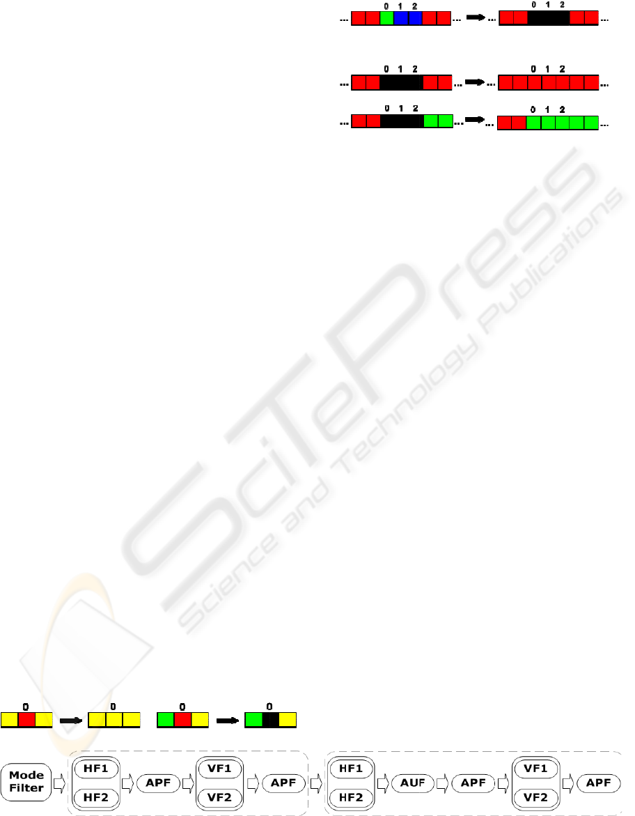
proposed algorithm. The rules for the two horizontal
simple filters are as follows:
A FAST POST-PROCESSING TECHNIQUE FOR REAL-TIME STEREO CORRESPONDENCE
491
• Chec
k
right a
n
differen
t
value eq
u
• Chec
k
right an
d
value, d
i
set its di
Fig
u
For ver
t
with ex
a
Fo
r
comple
m
applied
t
incorrec
t
changed
p
ixels.
T
areas, i
n
default
dependi
n
range. T
h
• If the
with th
e
the disp
a
it with t
h
An
and 3. I
n
filters
a
Adaptiv
e
Th
e
techniq
u
p
aramet
e
the resu
l
and vic
e
filtering
this, we
b
y intr
o
variable
area (w
i
undefin
e
(und_re
p
dis
p
ariti
e
scenes s
h
areas b
e
wrong “
c
k
for each pi
x
n
d left pixel
s
t
from that
p
i
x
u
al to the oth
e
k
fo
r
each pi
x
d
left pixels d
o
i
fferent from
sparity value
t
u
re 1 illustrat
e
t
ical filtering,
a
ctly the same
r
adaptive filt
e
m
entary funct
i
t
o areas whe
r
t
disparity v
a
depending
T
he second
f
n
order to pr
o
operation, it
s
n
g on the n
u
h
e rule for th
i
detected un
d
e
same dispa
r
a
rity value o
f
h
e disparity v
a
example of e
a
n
the rest of t
h
a
s Adaptive
e
Propagation
e
advantage o
u
e is that th
e
e
r setting, is
a
l
ted disparity
e
versa. Its us
operation ha
s
modify the e
f
o
ducing three
determines t
h
i
n_si
z
) and t
h
e
d area bet
w
p
) that ca
n
e
s. However,
h
ow that the
r
e
tween two
d
c
orrections”,
c
Figure
4
x
el in the dis
s
exhibit th
e
x
el. In this ca
s
e
r two pixels.
x
el in the dis
o
no
t
exhibit
t
the central p
t
o undefined.
e
s the horizo
n
two identic
a
rules but in
v
e
ring, two se
p
i
ons are use
d
r
e adjacent p
i
a
lues and its
s
on the nu
m
f
ilter is appl
o
pagate relia
b
s
size is ad
a
u
mber of un
d
i
s fil
t
er is as f
o
d
efined area
r
ity value, th
e
f
this object.
O
a
lue of the ne
a
a
ch filter is s
h
h
is work we
w
Undefined
(AP) filter, r
e
f the propose
e
user, throu
g
a
ble to increa
s
map with res
p
e is optional,
s
been descri
b
f
fectiveness
o
separate va
r
h
e maximum
h
e second o
n
w
een two
d
n
be repla
c
experimenta
l
r
eplacement
o
d
ifferent obje
c
c
aused either
b
4
: Diagram of t
h
parity map i
f
e
same disp
a
s
e, set its disp
a
parity map i
f
t
he same disp
a
ixel. In this
c
n
tal filtering r
u
a
l filters are
u
v
ertical directi
p
arate filters
w
d
. The first o
n
i
xels have si
m
s
ize is adapt
i
m
ber of inco
r
ied to unde
f
b
le disparitie
s
a
ptively mod
i
d
efined pixe
l
o
llows:
is among ob
j
e
n replace it
w
O
therwise re
p
a
rest object.
h
own in Figu
r
w
ill mention t
h
(AU) filter
e
spectively.
d pos
t
-
p
roce
s
g
h some ext
e
s
e the accura
c
p
ect of its de
n
while the de
f
b
ed above. T
o
o
f the AP filt
e
r
iables. The
undefined s
e
n
e the maxi
m
d
ifferent ob
j
c
ed by rel
i
l
results with
o
f large unde
f
c
ts produce
m
b
y the secon
d
h
e proposed po
f
the
a
rity,
a
rity
f
the
a
rit
y
c
ase,
u
les.
u
sed
on.
w
ith
n
e is
m
ilar
i
vely
r
rect
f
ined
s
. In
i
fied
l
s in
j
ects
w
ith
p
lace
r
es 2
h
ese
and
s
sing
er
nal
c
y of
n
sity
f
ault
o
do
e
ring
first
e
arch
m
um
j
ects
i
able
real
f
ined
m
ore
d
Fig
u
un
d
val
u
wit
h
un
d
onl
y
ne
a
int
r
the
obj
e
val
u
the
are
a
obj
e
p
ro
p
ver
t
use
AP
filt
e
un
d
the
N
o
t
b
lo
c
an
d
4
4.
1
Th
e
filt
e
Th
e
st-
p
rocessing a
l
Figure 1
:
Figure
u
re 3: Exam
p
efined area is
u
e and (b) wh
e
h
different disp
a
heuristic w
e
d
efined area
b
y
one dispari
t
a
rest object.
r
oduced a thi
r
maximum u
n
e
cts that can
u
e. If the un
d
filter determ
i
a
and propa
g
e
ct in each p
a
To summar
i
p
osed pos
t
-
pr
t
ical filters a
r
better the l
o
filters are u
s
e
rs to prop
a
d
efined areas.
diagram, we
t
ice that the
A
c
k, when reli
a
d
the detectio
n
HARD
W
1
Pre-pr
o
e
implement
a
e
r is straightf
o
e
filters proce
s
l
gorithm.
:
Rules for hori
2: Example o
f
(a)
(b)
p
les of AP
f
among object
s
e
n the undefin
e
a
rity values.
e
used or by
t
b
etween two
t
y value that
d
To elimin
a
r
d variable (
m
n
defined area
be replaced
d
efined area
e
i
nes the mid
p
g
ates the dis
p
a
rt.
i
ze, Figure 4
s
r
ocessing alg
o
r
e used inter
c
o
cal depth in
f
s
ed between
h
a
gate the c
o
In order to i
m
have separa
t
A
U filter is u
s
a
ble features
n
of unreliabl
e
W
ARE DE
S
o
cessin
g
a
tion of a s
i
o
rward and c
a
s
s one pixel
p
zontal filtering
f
AU filtering.
f
iltering: (a)
W
s
with the sam
e
e
d area is amo
n
t
he assumpti
o
different o
b
d
epends only
a
te these er
r
m
ax_und) to
d
between two
by only one
e
xceeds this
t
p
oint of the
u
p
arity values
s
hows a diagr
o
rithm. Horiz
c
hangeably i
n
f
ormation. In
h
orizontal an
d
o
rrect infor
m
m
prove the vi
s
t
ed it into t
w
s
ed only in t
h
have becom
e
e
areas is easi
e
S
CRIPTI
O
i
mple weigh
t
a
n be seen in
p
er clock cycl
e
.
W
hen the
e
disparity
n
g objects
o
n that an
b
jects has
from the
r
ors, we
d
etermine
different
disparity
t
hreshold,
u
ndefined
of each
am of the
ontal and
n
order to
addition,
d
vertical
m
ation in
s
ibility of
w
o blocks.
h
e second
e
stronger
e
r.
O
N
t
ed mean
Figure 5.
e
, so they
VISAPP 2008 - International Conference on Computer Vision Theory and Applications
492
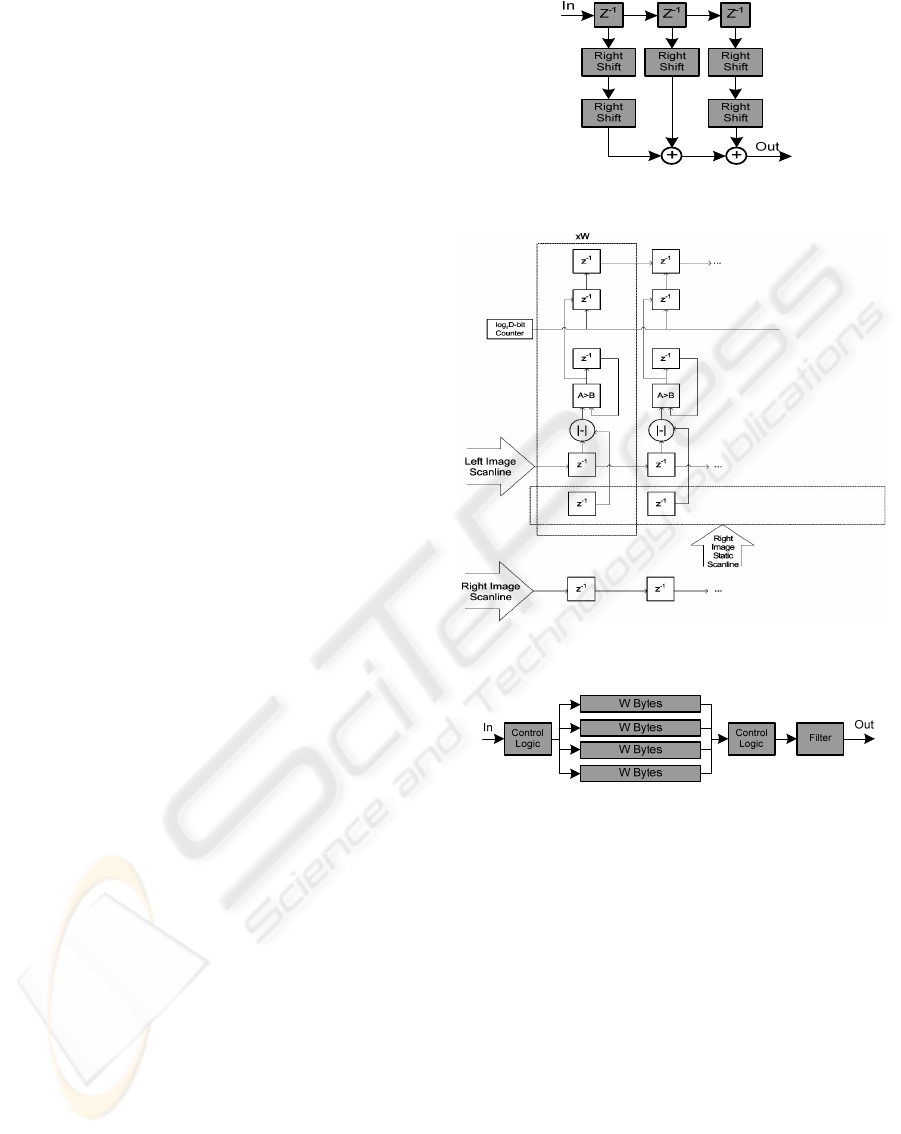
do not impose any speed degradation on the system.
4.2 Disparity Estimation
Due to the great computational complexity of the
disparity map estimation, a highly parallel structure
has been implemented, as shown in Figure 6. The
right image is fed in a parallel manner into the
adders, while the left is fed serially. On each column
of the array, the absolute difference of the pixels of
the two images is calculated, and compared to the
current minimum. After each scan line has been
processed, the disparities of the pixels are computed
and are sent to the next unit of the system.
4.3 Post-processing
The mode filter is the input block of the post-
processing unit. In order to calculate the mode value
in a 3x3 neighborhood, the unit shown in Figure 7
must be included. After the first three lines of
disparity values have been stored in the serial
memories, 3x3 blocks are fed into the mode filter,
while the next line is read. The control logic units
are used to route the input image to the respective
memory block, allowing the pipelined processing of
each 3x3 block.
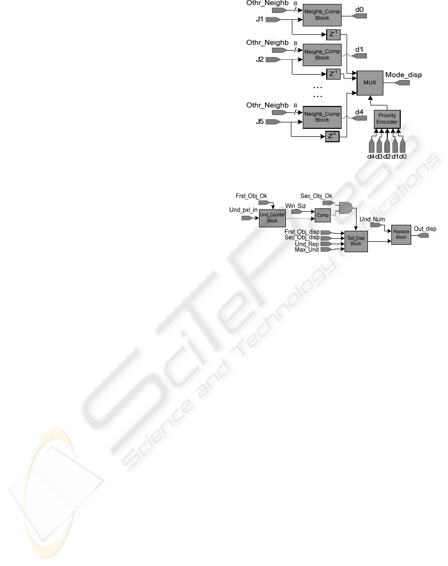
In the first stage of mode filter, which is
depicted in Figure 8, each ‘Neighb_Comp’ sub-
block compares one disparity value with the other
eight of the 3x3 neighborhood, and if it stands more
than 4 times, then the output is assigned as logic
one. The priority encoder generates an output based
on the highest ‘Neighb_Comp’ sub-block that emits
a logic one and, finally, the mux selects the mode
disparity for the central pixel.
The horizontal and vertical filtering blocks
present the simplest hardware architecture of our
system. For horizontal filters, only three log
2
D-bit
comparators are used to compare the neighboring
pixels and provide the proper results. Vertical filters
use a similar architecture, while the unit of Figure 7
must be included once again.
In AU filtering block, after the detection of a
reliable area, a counter calculates the unreliable
pixels in range. If the filtering rules are
accomplished, the unreliable pixels are modified to
undefined and the others remain unmodified, driving
the output of the filter in every clock cycle. AP
filter, which is demonstrated in Figure 9, is fed with
undefined pixels after the detection of a reliable
area. The ‘Und_Counter’ sub-block counts them and
Figure 5: Block diagram of weighted mean filter.
Figure 6: Disparity estimation unit.
Figure 7: Memory block for two-dimensional filtering.
the result is sent to ‘Replace’ sub-block. The
‘Sel_Disp’ sub-block selects the proper disparity
value and sends it to ‘Replace’ sub-block, in order
the undefined pixels to be replaced with that value.
4.4 Circuit Characteristics
All units described above operate in a fully pipelined
manner. Output latencies are not of importance,
since they are in the order of a few microseconds.
After an initial latency period, output is given once
per clock cycle. The total output latency of the
system depends on the width of the input images and
the values of the filtering parameters, that is 11
W +
4’Win_Siz’ + 38 clock cycles. This architecture was
implemented on an FPGA device of the Cyclone II
A FAST POST-PROCESSING TECHNIQUE FOR REAL-TIME STEREO CORRESPONDENCE
493
family of Altera Devices and the maximum
operating clock frequency was found to be 150
MHz. The proposed hardware architecture requires
3
W+21 8-bit registers, 2W+18D log
2
D-bit registers,
W+60 comparators, W subtraction elements, 1 4-bit
and 1 8-bit counter, 6 8-bit adders, 20 8-bit shifters,
4 log
2
D-bit MUXes and a small number of logic
gates.
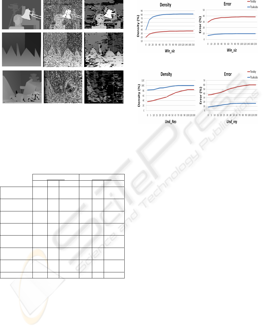
5 EXPERIMENTAL RESULTS
In this section, we present results for some image
pairs with different disparity ranges, using the test
procedure reported by Scharstein and Szeliski
(Scharstein and Szeliski, 2002), available at
www.middlebury.edu/stereo. The initial and the
resulting disparity maps for the default filtering
operation are shown in Figure 10, where black pixels
represent the undefined pixels and not zero disparity.
It can be seen that before the filtering process,
the initial disparity maps present high number of
incorrect reconstructions and object boundaries are
not clearly distinguishable. After post-processing,
they are significantly cleaner and the cluttered
background has been significantly improved. For
example, the camera on the tripod in Figure 12(d) is
clearly distinguishable, while in Figure 12(c) it is
part of the background. As with all area-based
methods, our algorithm performs better on textured
areas, whilst in textureless and occluded regions the
replacement of incorrect disparities is satisfactory.
The proposed algorithm is very fast and can be
implemented in real-time stereo systems like
autonomous mobile robot applications. In Table 1, a
comparison of our algorithm with other semi-dense
approaches is presented. We also mention that
density for Teddy data set is 36.48%, where 71.3%
of them are found correctly in 3.1 msec. In terms of
performance, we tested our algorithm on a notebook
Intel Pentium M 1.5 GHz, while the execution times
for other algorithms are as given by their authors.
Quantitative results in Table 1 show that the
proposed algorithm presents higher map density than
most of the compared algorithms, but also higher
error rate. However, other related approaches use
some of the state-of-the-art algorithms and are
lacking in robustness, while in our approach we use
only some simple computations. Furthermore, in
many real-time applications, it is more important to
identify adequately and fast the space occupied by
each object in the scene, rather than to have an
accurate but slow reconstruction of it. Therefore, an
increase in error rate can be balanced by the signifi-
Figure 8: Mode filtering block.
Figure 9: AP filtering block.
cant increase in computational speed, which is
essential for time critical applications. Moreover,
results on Teddy data set indicate that it can retain
its robustness even for large-size images with
difficult scenes and larger disparity ranges.
Figures 11 and 12 show the plots of density and
error rate as a function of variables
win_siz and
und_rep. The results indicate that images with larger
undefined areas and larger disparity range present
smaller density and higher error rate than the smaller
ones. We should also notice that our approach is not
dependent on the disparity range but only on the size
of the images.
6 CONCLUSIONS
In this paper, we have presented a new post-
processing algorithm and its hardware
implementation. A non-linear filtering procedure
and a way to adaptively change in real time the
density and the accuracy of the extracted disparity
maps, provide a unique feature against other related
methods, taking advantage of a fully pipelined
architecture. The extracted disparity maps are semi-
dense but the localization of objects is quite good,
suitable for many real-time applications, where high
performance and satisfying accuracy are essential.
VISAPP 2008 - International Conference on Computer Vision Theory and Applications
494
Experi
m
demons
t
compar
a
time a c
l
REF
E
Boykov,
Appr
o
IEE
E
Intell
i
(
Figure 1
(middle
r
Ground t
r
map.
Table 1
:
p
ercenta
g
p
ercenta
g
more tha
n
Proposed
Algorith
m
Gong an
d
Yang (20
0
Gong an
d
Yang (20
0
Veksler
(2002)
Kim et al
(2005)
Veksler
(2003)
Szel.&Sc
h
(2002)
Sara (20
0
m
ental results
t
rated that
a
ble to other
m
l
ear advantag
e
E
RENCES
Y., Veksler,
o
ximate Energ
y
E
Transactions
i
gence, 23(11),
a)
0: Results o
n
r
ow) and Te
d
r
uth, (b) initia
l
:
Comparativ
e
g
e of matches
g
e of bad pix
e
n
1.
T
s
D(%) e
(
m
81.7
9
d
0
3)
71 1
d
0
5)
76 0
66 0
.
95.2 0
75 0
h
arst.
73
0
2) 45
1
with real-w
o
the propos
e
m
ethods, indi
c
e
regarding c
o
O., Zabih,
y
Minimizatio
n
on Pattern An
a
pp. 1222-123
9
(b)
n
Tsukuba (t
o
d
dy (bottom r
o
l
disparity ma
p
e
results. D
e
generated, er
r
e
ls far from th
s
ukuba
(
%) Time(s)
D
9
.8 0.0021
8
.03 0.047
.32 0.062
.38 1
.24 4.4
9
.36 6
4 -
1
.4 -
o
rld images
h
e
d algorith
m
c
ating at the
s
o
mputation ti
m
R., (2001).
n
via Graph Cu
t
a
lysis and Ma
c
9
.
(c)
o
p row), Saw
t
o
w) data sets
p
, (c) final dis
p
e
nsity (D) is
r
or rate (e) i
s
e true disparit
y
Sawtooth
D
(%) e(%) Ti
m
8
7.9 33.7 0.0
72 0.23 0.
0
89 0.07 0.
1
76 1.62
6
9
8.9 0.07 1
1
87 0.54
1
- -
52 1.6
h
ave
m
is
s
ame
m
e.
Fast
t
s. In
c
hine
Fi
g
Fig
u
Bro
Go
n
Go
n
Ki
m
Sar
a
Sch
Sze
l
Ve
k
Ve
k
t
ooth
. (a)
p
arity
the
s
the
y
by
m
e(s)
025
0
93
1
41
6
1
.8
1
3
-
-
g
ure 11: Densit
y
u
re 12: Densti
y
w
n, M.Z.,
B
Advances in
Transactions
Intelligence, 2
5
n
g, M. an
d
Ya
n
Using Reliabi
l
Consistency
C
Computer Visi
o
n
g, M. and Y
a
stereo match
i
p
rogramming.
A
nalysis and
M
1003.
m
, J., Lee, K.M
.
stereo matchin
with generali
z
Computer Visi
1075-1082.
a
, R., (2002)
.
Component o
f
Conf. Comput
e
arstein, D. an
d
Evaluation
Corresponden
c
of Computer
V
l
iski, R. and
S
p
ixel Stereo
M
Computer Visi
o
k
sler, O., (20
0
Stereo Corres
p
Computer Visi
o
k
sler, O., (200
3
Corresponden
c
Computer Vis
i
694.
y
and error rate
y
and error rate
B
urschka, D.,
Computatio
n
on Pattern
A
5
(8), pp. 993–1
n
g, Y.-H., (20
0
l
ity-Based Dy
n
C
onstraints. In
o
n, pp. 610-61
7
a
ng, Y.-H., (2
i
ng using r
e
In IEEE T
r
M
achine Intel
l
.
, Choi, B.T., L
g using two-
p
a
z
ed ground c
o
on and Patter
n
.
Finding th
e
f
Stereo Matc
h
e
r Vision, vol.
2
d
Szeliski, R.,
(
of Dense
c
e Algorithms.
V
ision, 47(1), p
p
S
charstein, D.,
M
atching. In
E
o
n, vol. 2, pp.
5
0
2). Dense F
e
p
ondence. In
I
o
n, 47(1-3),
p
p
.
3
). Extracting
D
c
e with Graph
C
i
on and Patte
r
as a function
o
as a function o
f
Hager, G.D
.
n
al Stereo.
A
nalysis and
008.
0
3). Fast Stere
o
n
amic Progra
m
Proc. IEEE
7
.
005). Fast un
a
e
liability-
b
ased
r
ansactions o
n
l
igence, 27(6),
ee, S.U., (200
5
ss dynamic pr
o
o
ntrol points.
n
Recognition,
e
Largest Un
a
h
ing. In Proc.
2
, pp. 900-914.
(
2002). A Tax
o
Two-Frame
In Internation
a
p
. 7-42.
(2002). Sym
m
E
uropean Con
f
5
25-540.
e
atures for S
e
I
nternational
J
. 247-260.
D
ense Features
C
uts. In Proc. I
E
r
n Recognition
,
o
f win_siz.
f
und_rep.
.
, (2003).
In IEEE
Machine
o
Matching
m
ming and
Conf. on
a
mbiguous
dynamic
n
Pattern
pp. 998–
5
). A dense
o
gramming
In IEEE
vol. 2, pp.
a
mbiguous
European
o
nomy and
Stereo
a
l Journal
m
etric Sub-
f
erence on
e
mi-Dense
J
ournal of
for Visual
E
EE Conf.
,
pp. 689–
A FAST POST-PROCESSING TECHNIQUE FOR REAL-TIME STEREO CORRESPONDENCE
495
