
A SIGNAL-SYMBOL LOOP MECHANISM FOR ENHANCED EDGE
EXTRACTION
Sinan Kalkan, Florentin W
¨
org
¨
otter
Bernstein Center for Computational Neuroscience, Univ. of G
¨
ottingen, Germany
Shi Yan, Volker Kr
¨
uger
Medialogy Lab, Aalborg Univ. Copenhagen, Denmark
Norbert Kr
¨
uger
Cognitive Vision Lab, Univ. of Southern Denmark, Denmark
Keywords:
Feedback Mechanisms, Edge Extraction, Rigid Body Motion, Signal–Symbol Loop.
Abstract:
The transition to symbolic information from images involves in general the loss or misclassification of infor-
mation. One way to deal with this missing or wrong information is to get feedback from concrete hypotheses
derived at a symbolic level to the sub-symbolic (signal) stage to amplify weak information or correct misclas-
sifications. This paper proposes such a feedback mechanism between the symbolic level and the signal level,
which we call signal symbol loop. We apply this framework for the detection of low contrast edges making
use of predictions based on Rigid Body Motion. Once the Rigid Body Motion is known, the location and
the properties of edges at a later frame can be predicted. We use these predictions as feedback to the signal
level at a later frame to improve the detection of low contrast edges. We demonstrate our mechanism on a real
example, and evaluate the results using an artificial scene, where the ground truth data is available.
1 INTRODUCTION
Processing in most artificial vision systems as well as
in the human visual system starts with the extraction
of information based on linear and non-linear filter-
ing operations (figure 1) by which, e.g., local orienta-
tion, magnitude, and phase become computed. We
call this level of processing ’signal-level’ since the
original signal is usually reconstructible from it; i.e.,
the signal-level information is pixel-wise, continuous
and complete.
In a next step, we extract discrete descriptors for
line structures using the method of (Kr
¨
uger et al.,
2004). We call this level ’symbol-level’ since at this
stage the semantic information represented in single
pixel values is made explicit. Symbolic information is
sparse, condensed and semantically rich, and usually,
the original signal is not fully reconstructible from it.
Inclusion of contextual information requires the
exchange of information over large spatial or tempo-
ral distances (in case of, e.g., large object motions or
saccades) and even the use of world knowledge stored
in long term memory (as for example in the Dalma-
tian dog illusion (Gregory, 1970)
1
). Such exchange
of information can only be formulated sub-optimally
on the signal-level in a pixel-wise representation since
the number of pairwise relations would simply be-
come too large or the amount of computer memory
required would exceed reasonable bounds. The ad-
vantage of a symbolic level is that reasoning over spa-
tial and temporal changes as well as interaction with
the world knowledge stored in the memory becomes
much easier. In this paper, we introduce a framework
of, so called, ’signal-symbol loops’ and apply it in the
context of edge extraction.
The transition to the symbolic level requires the
transformation of information at the pixel-wise and
continuous signal level to a discrete and condensed
symbolic level. This usually requires the use of
thresholds. Binary decisions involving such a thresh-
olding usually results in either a loss of information
below the threshold or in the extraction of false pos-
itives caused by signal noise (see figure 2). In the
case of finding line segments, for example, a thresh-
1
The illusion is also available online at http://www.
michaelbach.de/ot/cog_dalmatian/index.html
214
Kalkan S., Wörgötter F., Yan S., Krüger V. and Krüger N. (2008).
A SIGNAL-SYMBOL LOOP MECHANISM FOR ENHANCED EDGE EXTRACTION.
In Proceedings of the Third International Conference on Computer Vision Theory and Applications, pages 214-221
DOI: 10.5220/0001077602140221
Copyright
c
SciTePress
for frame
Feedback
for frame
Feedback
Left Image
Right Image
Linear
Nonlinear
Filtering
Nonlinear
Filtering Filtering
Linear
Filtering
SIGNAL LEVEL
RBM
3D Symbolic
Predictions for
SYMBOL LEVEL
Descriptors Descriptors
3D Symbolic
Descriptors at
2D Symbolic 2D Symbolic
Stereo Stereo
TIME
θ
θ
t + 1 t + 1
mm
t + 1
t
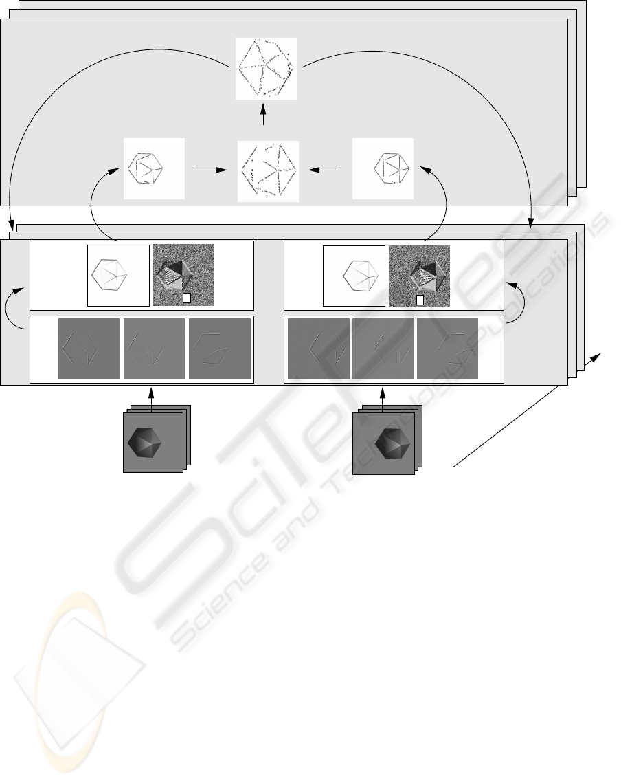
Figure 1: A rough outline of the signal-symbol loop mechanism, which is proposed in this paper. The linear filtering is
achieved by Gabor wavelets (only real components of the three out of eight responses are shown). The non-linear filtering
level contains the magnitude m and the orientation θ information. From the signal-level information, 2D symbolic edge
descriptors are extracted. These descriptors are then matched to the other camera view to reconstruct 3D symbolic edge
descriptors. The known RBM is used to estimate the 3D symbolic descriptors at a later frame t + 1, whose projections to the
respective images at time t +1 then provide the feedback to the filter processing layer. Note that the predicted 3D descriptors
at frame t + 1 are shown from a different perspective, and therefore, are not as smooth as the 3D primitives at frame t.
old is introduced to determine contrast sensitivity.
Using a high threshold (i.e., low contrast sensitiv-
ity) produces reliable (i.e., true positive) but (most
of the time) incomplete set of line segments (figure
2). Using a low threshold (i.e., high contrast sensi-
tivity), on the other hand, can produce a more com-
plete set of line segments, which usually include also
noisy information (figure 2). This dilemma between
incomplete-but-reliable versus complete-but-noisy is
faced by all computer vision algorithms which require
some thresholding. By local processing alone relevant
information can not be distinguished from informa-
tion caused by, e.g., signal noise or other sources of
ambiguity.
One way to gain the information lost during the transi-
tion to the symbolic level is to review the signal based
on concrete hypotheses generated by reasoning on the
symbolic level being fed back to the signal level to
amplify the weak but consistent information. We call
this feedback mechanism ’signal-symbol loop’ (see
also (Kr
¨
uger, 2005)).
To make information at the symbolic level compara-
ble to the signal, it is required to transform the sym-
bolic information back in a form that makes it com-
parable to the signal level. This transformation can be
regarded as taking the inverse of a symbolic descrip-
tion, and therefore it is called the feedback function in
the rest of the paper. This feedback function can be
considered as the inverse of a symbol since it trans-
form the symbolic information back to the signal-
A SIGNAL-SYMBOL LOOP MECHANISM FOR ENHANCED EDGE EXTRACTION
215

(a) (b) (c)
Figure 2: (a) An artificial image with low-contrast edges.
(b) The result of the Sobel operator (Nixon and Aguado,
2002) with a high threshold. (c) The result of the Sobel
operator with a low threshold (in order to extract the weak
edges), which produces unwanted edges due to the shading
((c) is scaled independently for the sake of better visibility).
level information.
This paper proposes a concrete signal-symbol
loop mechanism to improve the extraction of low-
contrast edges by making use of motion information,
namely, the change of a symbolic local edge descrip-
tor under a Rigid Body Motion (RBM). In our paper,
the change of position and orientation of this descrip-
tor under an RBM can be formulated explicitly: Af-
ter estimating the position of a 3D edge descriptor at
a later frame, the image projection of the estimated
3D descriptor provides feedback to the filter process-
ing level. The feedback information states that there
must be an edge descriptor with certain properties at
a certain position. The filter processing level then en-
hances the information at a position if the feedback is
consistent with the original image information. The
rough outline of the mechanism that we propose is
given in figure 1.
The approach we introduce here is related to
’adaptive thresholding’ approaches which are for ex-
ample used in the area of image segmentation. These
can also recover low-contrast edges by adjusting the
threshold. This adjustment, however, is based on the
local distribution of image intensities (see, e.g., (Gon-
zales and Woods, 1992)). Our approach differs from
adaptive thresholding since it makes use of symbolic
information that facilitates a more global and also a
more directed mechanism rather than local intensity
distribution. Moreover, as we discuss at the end of
the paper, the novelty of the current paper is in the
proposal of a symbol-to-signal feedback mechanism
that can be applied also in other contexts.
The idea of using of feedback in vision systems is
not new (Aloimonos and Shulman, 1989; Angelucci
et al., 2002; Galuske et al., 2002; Bullier, 2001). For
computational models the interested reader is directed
for example to (Bayerl and Neumann, 2007) for mo-
tion disambiguation or (Bullier, 2001) for modelling
at the neuronal level for long-range information ex-
change between neurons. Our work is different from
the above mentioned works in that we introduce a
feedback mechanism between different layers of pro-
cessing, i.e., the signal-level and the symbol-level,
and we apply it in a different context.
The paper is organized as follows: In section 2,
we introduce the symbolic edge descriptors and the
concept of RBM that are utilized in this paper. Section
3 describes our feedback mechanism. In section 4,
we present and discuss the results, and the paper is
concluded in section 5.
2 SYMBOLIC DESCRIPTORS
AND PREDICTIONS
In this section, we give a brief description of the im-
age descriptors that we use to represent local scene
information at the symbolic level (section 2.1). These
descriptors represent local image information in a
condensed way and by that transform the local sig-
nal information to a symbolic level. In section 2.2,
we briefly comment on Rigid Body Motion which we
use as the underlying regularity of predictions on the
symbolic level.
2.1 Multi-modal Primitives
The concept of multi-modal primitives has been first
introduced in (Kr
¨
uger et al., 2004). These primi-
tives are local multi-modal scene descriptors, which
are motivated by the hyper-columnar structures in V1
(Hubel and Wiesel, 1969).
In its current state, primitives can be edge-like or
homogeneous and carry 2D or 3D information. For
the current paper, only edge-like primitives are rele-
vant. An edge-like 2D primitive (figure 3(a)) is de-
fined as:
π = (x,θ,ω, (c
l
,c
m
,c
r
)), (1)
where x is the image position of the primitive; θ is the
2D orientation; ω represents the local phase, the color
is coded as three vectors (c
l
,c
m
,c
r
), corresponding to
the left (c
l
), the middle (c
m
) and the right side (c
r
) of
the primitive. See (Kr
¨
uger et al., 2004) for more in-
formation about these modalities and their extraction.
Figure 4 shows the extracted primitives for an exam-
ple scene.
A primitive π is a 2D descriptor which can be used to
find correspondences in a stereo framework to create
3D primitives (as introduced in (Kr
¨
uger et al., 2004))
which have the following formulation:
Π = (X,Θ,Ω,(c
l
,c
m
,c
r
)), (2)
VISAPP 2008 - International Conference on Computer Vision Theory and Applications
216
(2)
(3)
(4)
(1)
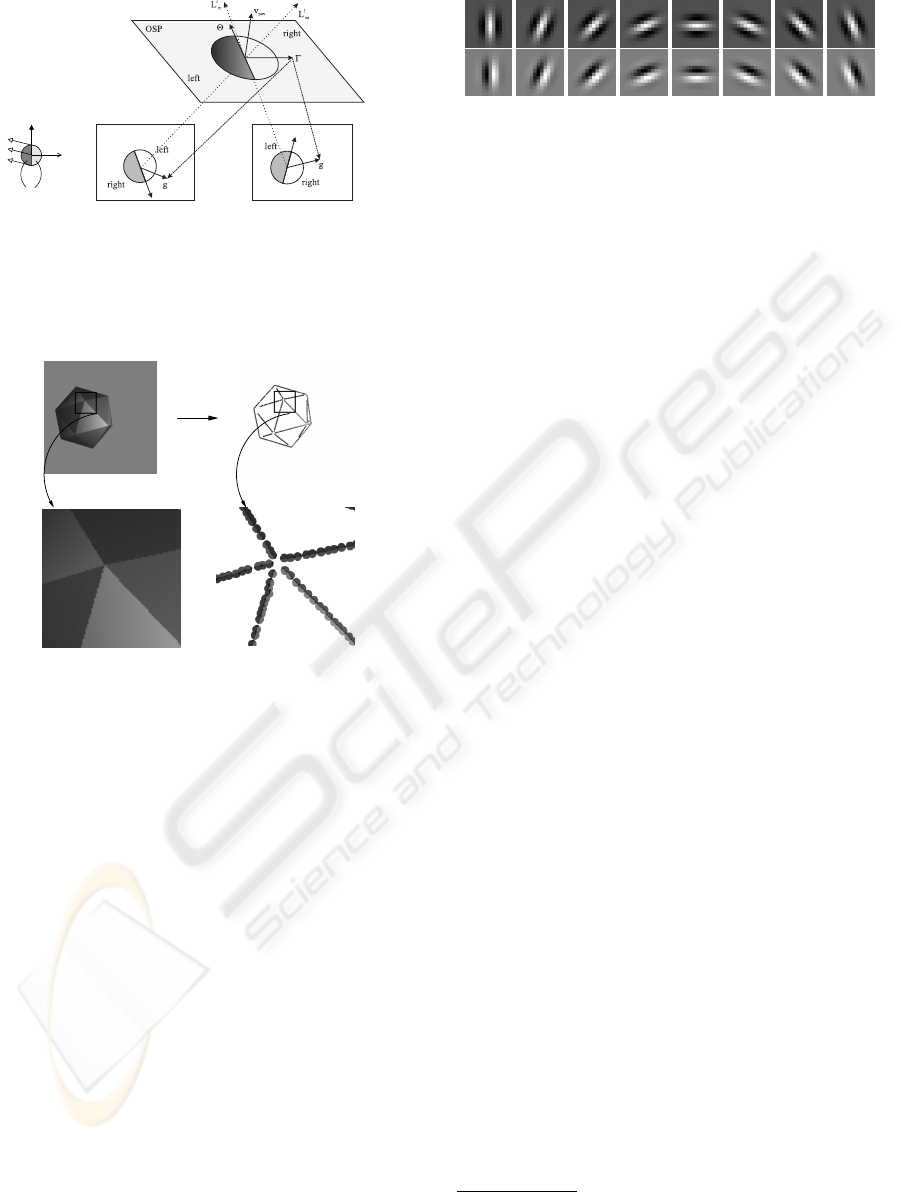
(a) (b)
Figure 3: (a) An edge-like primitive: 1) represents the ori-
entation of the primitive, 2) the phase, 3) the color and 4)
the optic flow. (b) Two corresponding 2D edge primitives
can reconstruct a 3D primitive.
(a) (b)
(c)
(d)
Figure 4: Extracted edge primitives (b) for the example im-
age in (a). Extracted primitives for the region of interest in
(c) is shown in (d).
where X is the 3D position; Θ is the 3D orientation.
Appearance based information is coded by general-
ising local phase and color of the two corresponding
2D primitives. The reconstruction of a 3D primitive
from two corresponding 2D primitives is exemplified
in Figure 3(b).
Knowledge of the camera parameters allows
defining a projection relation P from a 3D primitive
Π to an image, which produces a 2D primitive
ˆ
π:
ˆ
π = P (Π). (3)
The projection
ˆ
π of a 3D primitive Π is used in section
3 for computing the feedback of a prediction.
2.2 Rigid Body Motion (RBM)
A Rigid Body Motion describes the motion (i.e.,
translation and rotation) of rigid objects; i.e., objects
where the distance between any two particles on the
object remains the same throughout the motion.
A RBM associates a 3D entity e
t
in the first frame
Figure 5: Real (first row) and imaginary (second row) parts
of eight orientation Gabor wavelets.
to another entity e
t+∆t
in the second frame:
e
t+∆t
= RBM(e
t
). (4)
Application of equation 4 requires computation of ro-
tation and translation, which can be achieved by find-
ing correspondences between 3D entities e
t
and e
t+∆t
(see, e.g., (Faugeras, 1993)).
Knowledge of the RBM allows estimation of the
3D entities, in our case the primitives, at a later frame:
ˆ
Π
t+∆t
i
= RBM
t→t+∆t
(Π
t
i
). (5)
In this paper, the ground truth RBM is known either
because the scene is generated using OpenGL, or be-
cause the object is rotated with a robot arm whose mo-
tion is known. See (Faugeras, 1993) for more infor-
mation about RBM and RBM estimation methods.
3 FORMALIZATION OF THE
SIGNAL-SYMBOL LOOP
The RBM predicts a 3D primitive at a later frame.
This prediction is formulated at the symbolic level
since it uses the 3D primitives. The projection of this
primitive from the symbolic level into the image (us-
ing the projection relation defined in equation 3) pro-
vides a position and an orientation feedback to the fil-
tering operations (i.e., the signal level). At the filter-
processing level, this feedback at discrete positions is
combined with the extracted filter responses.
At the signal level, we use complex Gabor
wavelets as a basic filtering operation (Lee, 1996).
The Complex Gabor wavelet response G is computed
on eight different orientations; i.e., G(x,y,c
i
) for i ∈
[1,8] (figure 5). The feedback of a prediction with im-
age coordinate (x
0
,y
0
) and orientation θ
0
(falling into
channel c
0
)
2
is distributed over the Gabor channels
2
The channel c
i
that an orientation θ ∈ [0,π) corre-
sponds to is computed using i = round(N · θ/π) where
N = 8 is the total number of channels.
A SIGNAL-SYMBOL LOOP MECHANISM FOR ENHANCED EDGE EXTRACTION
217

using the following Gaussian Feedback Function:
F(x,y,c
i
) =
1
C
exp
−
1
2
n
[(x − x
0
)cosθ
0
+ (y − y
0
)sinθ
0
]
2
σ
x
+
[−(x − x
0
)sinθ
0
+ (y − y
0
)cosθ
0
]
2
σ
y
+
(c
i
− c
0
)
2
σ
c
o
, (6)
where C is a normalization constant computed using:
C =
1
(2π)
1/2
(σ
2
x
+ σ
2
y
+ σ
2
θ
)
, (7)
where we empirically set σ
x
= 4,σ
y
= 1,σ
θ
= 1. The
Gaussian Feedback Function in equation 6 is an es-
sential part of the signal-symbol loop proposed in
this paper since it distributes the incomplete, con-
densed and discrete symbolic information in a 2D
primitive
ˆ
π = P (RBM(π)) to the complete, contin-
uous and pixel-wise signal-level information: i.e.,
F(
ˆ
π) = F(x,y,c
i
) for i = 1,..,8.
The original Gabor responses and the feedback
F(x,y,c
i
) from the symbolic level, i.e., RBM estima-
tion, are combined into a modified Gabor function
ˆ
G(x,y,c
i
) as follows:
ˆ
G
R
(x,y,c
i
) = G
R
(x,y,c
i
) + w · F(x,y,c
i
), (8)
ˆ
G
I
(x,y,c
i
) = G
I
(x,y,c
i
) + w · F(x,y,c
i
). (9)
where G
R
and G
I
are the complex and the imaginary
parts of the respective orientation channels. We de-
termine the weight w based on the consistency of the
predicted orientation (i.e., the orientation of the 2D
projection of the predicted 3D primitive) with the ex-
tracted Gabor responses as follows:
w =
"
1 −
1
N · π/2
∑
(x
0
,y
0
)∈Ω
θ
0
− θ
c
i
(x
0
,y
0
)
#
, (10)
where θ
0
is the predicted orientation, the variables
(x
0
,y
0
) run over a local neighborhood Ω whose size
is N.
From the complex filter responses on eight chan-
nels, the magnitude m and the orientation θ are triv-
ial to compute, and the details are skipped (see, e.g.,
(Haglund and Fleet, 1994)).
4 RESULTS
In this section, we present and evaluate the results of
our mechanism on an artificial (section 4.1) and a real
scene (section 4.2).
(a) (b)
Figure 6: (a) Artificial scene generated using OpenGL. (b)
Wireframe drawing mode in OpenGL provides ground truth
for evaluating the feedback.
4.1 Artificial Scene
The artificial data that we used is icosahedron (i.e.,
a polyhedron having 20 faces) shown in figure 6(a).
The icosahedron is generated using OpenGL which
allows us to exercise a certain RBM and make use of
the ground truth information to evaluate the perfor-
mance. The ground truth is computed using the wire-
frame drawing mode in OpenGL (shown in figure
6(b)). We define a feedback true-positive if the image
point is close to an edge of the wireframe (namely,
the distance is less than three pixels); a feedback is
false-positive if it is not a true-positive.
Figure 7 shows the results on the artificial scene.
We see in figure 7(e) that many of the 2D primitives
are not extracted due to the low contrast. However,
knowing the RBM allows the missing edges in fig-
ure 7(e) to be extracted with feedback from RBM as
shown in figure 7(f).
In figure 8, the improvement of the feedback
mechanism is evaluated using the ground truth val-
ues. The ROC (Receiver Operating Characteristics)
curve in figure 8(a) shows that the proposed feedback
mechanism produces a better true to false positive ra-
tio than without the feedback mechanism. In figures
8(b) and (c), the true and false positives on the origi-
nal image, respectively without and with the feedback
mechanism, are displayed (the false-positives are due
to shading as shown in figure 2). We see that the
feedback mechanism increases the amount of the true
positives while decreasing the false positives. Note
that the false positives are mostly due to shadows in
homogeneous areas of the icosahedron, which some-
times produces edge descriptors which are instable
over time. The amount of the true and false positives
for different energy (i.e., magnitude) thresholds are
displayed in figures 8(d) and (e). A threshold value
n means that only edge descriptors whose energy is
below n are considered for the evaluation. For exam-
ple, a threshold of n = 1.0 means that all descriptors
(edge and non-edge) are included. We see that at all
energy thresholds, the feedback mechanism produces
a higher true-to-false positive ratio.
VISAPP 2008 - International Conference on Computer Vision Theory and Applications
218
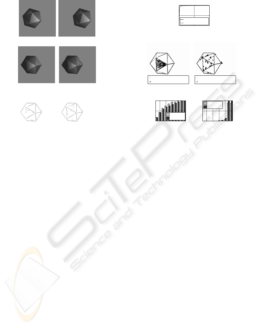
(a) (b)
(c) (d)
(e) (f)
Figure 7: (a)-(b) Left and right frames at time t. (c) Left
frame at time t + 1. (d) Image projection of the predicted
3D primitives in frame t + 1. (e) 2D primitives extracted in
frame t +1 without feedback. (f) 2D primitives extracted in
frame t + 1 with feedback.
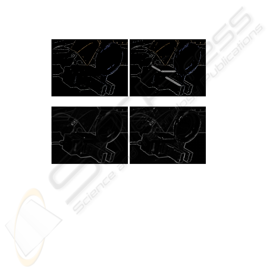
4.2 Real Scene
The real scene involves a robot arm and an object
grasped by the robot arm (figure 9). The robot arm ex-
ecutes a known RBM, and our system uses the RBM
to improve the feature extraction.
Figure 10(a) shows the extracted primitives with-
out feedback. We see that some of the edges are not
extracted due to low contrast. However, the knowl-
edge of RBM can feed back and improve the extrac-
tion of the edges (figure 10(b)). Figures 10(c) and (d)
show that the extraction of the magnitude is improved
with the feedback.
5 CONCLUSIONS
This paper has proposed a novel feedback mechanism
to improve the extraction of low contrast edges. Spe-
cific for this mechanism is that information is trans-
formed to a symbolic level on which symbolic reason-
ing leads to predictions that then become fed back to
the signal level. For this, the prediction that has been
generated on a symbolic level needs to be inverted to
become comparable at the signal level.
In the current paper, symbolic reasoning is re-
false−positive rate
true−positive rate
ROC curve
0 0.5 1
0
0.5
1
With Feedback
Without Feedback
(a)
324 true−positives found
90 false−positives found
(b)
362 true−positives found
45 false−positives found
(c)
threshold
true−positive rate
true−positives
0.2 0.4 0.6 0.8 1
0
0.5
1
With FB
Without FB
(d)
threshold
false−positive rate
false−positives
0.2 0.4 0.6 0.8 1
0
0.5
1
With FB
Without FB
(e)
Figure 8: (a) ROC curve for artificial scene. (b) True and
false positives for primitives whose magnitude is above a
magnitude threshold of 0.4 without feedback. (c) True and
false positives for primitives whose magnitude is above a
magnitude threshold of 0.4 with feedback. (d) True posi-
tives for primitives with and without feedback for different
magnitude thresholds. A threshold n means that only de-
scriptors whose magnitude is below n are considered. (e)
True positives for primitives with and without feedback for
different magnitude thresholds. A threshold n means that
only descriptors whose magnitude is below n are consid-
ered.
stricted to the change of a symbolic descriptor under
a rigid body motion. However, we claim that the in-
troduced mechanism is also applicable to other forms
of symbolic reasoning, for example by using stored
object knowledge to predict edges at weak structures
after an object hypothesis has been aligned with the
current scene (as for example in the Dalmatian dog
illusion (Gregory, 1970)). These issues are being ad-
dressed in our ongoing research.
ACKNOWLEDGEMENTS
We would like to thank Nicolas Pugeault and Emre
Bas¸eski for fruitful discussions. This work is sup-
ported by the European Drivsco project (IST-FP6-
FET-016276-2).
A SIGNAL-SYMBOL LOOP MECHANISM FOR ENHANCED EDGE EXTRACTION
219
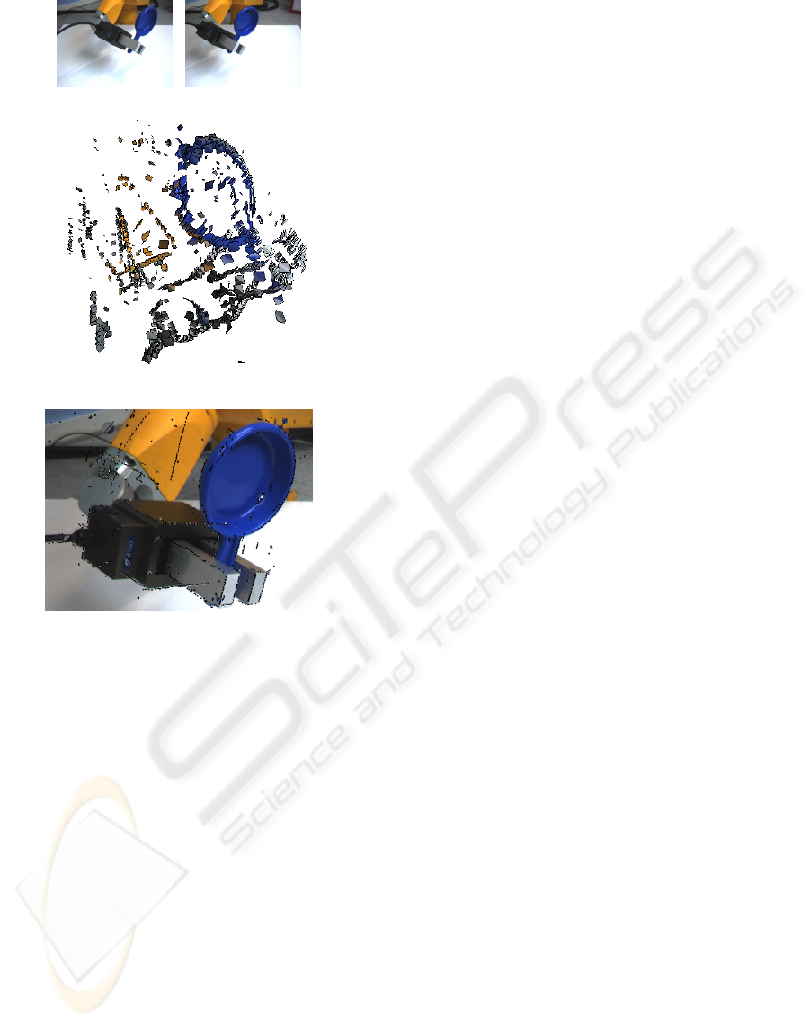
(a) (b)
(c)
(d)
Figure 9: (a)-(b) Left and right frames at time t. (c) 3D
primitives at time t (extracted from (a) and (b)). (d) The
projection of the predicted 3D primitives in (c) shown over
the image taken at frame t + 1.
REFERENCES
Aloimonos, Y. and Shulman, D. (1989). Integration of Vi-
sual Modules — An extension of the Marr Paradigm.
Academic Press, London.
Angelucci, A., Levitt, J. B., Walton, E. J. S., Hupe, J.-M.,
Bullier, J., and Lund, J. S. (2002). Circuits for Local
and Global Signal Integration in Primary Visual Cor-
tex. J. Neurosci., 22(19):8633–8646.
Bayerl, P. and Neumann, H. (2007). Disambiguating vi-
sual motion by form–motion interaction — a compu-
tational model. International Journal of Computer Vi-
sion, 72(1):27–45.
Bullier, J. (2001). Integrated model of visual processing.
Brain Research Reviews, 36:96–107(12).
Faugeras, O. (1993). Three–Dimensional Computer Vision.
MIT Press.
Galuske, R. A. W., Schmidt, K. E., Goebel, R., Lomber,
S. G., and Payne, B. R. (2002). The role of feed-
back in shaping neural representations in cat visual
cortex. Proceedings of the National Academy of Sci-
ence, 99:17083–17088.
Gonzales, R. and Woods, R. (1992). Digital Image Process-
ing. Addison-Wesley Publishing Company.
Gregory, R. L. (1970). The intelligent eye. McGraw-Hill
Book Company, New York.
Haglund, L. and Fleet, D. J. (1994). Stable estimation of
image orientation. In ICIP (3), pages 68–72.
Hubel, D. and Wiesel, T. (1969). Anatomical demonstra-
tion of columns in the monkey striate cortex. Nature,
221:747–750.
Kr
¨
uger, N. (2005). Three dilemmas of signal- and symbol-
based representations in computer vision. Workshop
on Brain, Vision and Intelligence, BVAI, Naples, Italy.
Kr
¨
uger, N., Lappe, M., and W
¨
org
¨
otter, F. (2004). Bio-
logically motivated multi-modal processing of visual
primitives. The Interdisciplinary Journal of Artificial
Intelligence and the Simulation of Behaviour, 1(5).
Lee, T. S. (1996). Image representation using 2d gabor
wavelets. IEEE Trans. Pattern Anal. Mach. Intell.,
18(10):959–971.
Nixon, M. S. and Aguado, A. S. (2002). Feature extraction
& image processing. Butterworth Heinmann/Newnes.
VISAPP 2008 - International Conference on Computer Vision Theory and Applications
220
(a) (b)
(c) (d)
Figure 10: (a) The primitives extracted at frame t + 1 without feedback. (b) The primitives extracted at frame at t + 1 with
feedback. The gray area denotes the extracted descriptors which are lost without feedback mechanism. (c) The magnitude
image of frame t + 1 without feedback. (d) The magnitude image of the updated frame at t + 1 with feedback.
A SIGNAL-SYMBOL LOOP MECHANISM FOR ENHANCED EDGE EXTRACTION
221
