
HIGH-SPEED IMAGE FEATURE DETECTION USING FPGA
IMPLEMENTATION OF FAST ALGORITHM
Marek Kraft, Adam Schmidt and Andrzej Kasi´nski
Institute of Control and Information Engineering, Pozna´n University of Technology, Piotrowo 3A, 60-965 Pozna´n, Poland
Keywords:
Image processing, feature detection, FPGA.
Abstract:
Many of contemporary computer and machine vision applications require finding of corresponding points
across multiple images. To that goal, among many features, the most commonly used are corner points. Cor-
ners are formed by two or more edges, and mark the boundaries of objects or boundaries between distinctive
object parts. This makes corners the feature points that used in a wide range of tasks. Therefore, numerous
corner detectors with different properties have been developed.
In this paper, we present a complete FPGA architecture implementing corer detection. This architecture is
based on the FAST algorithm. The proposed solution is capable of processing the incoming image data with
the speed of hundreds of frames per second for a 512×512, 8-bit gray-scale image. The speed is comparable
to the results achieved by top-of-the-shelf general purpose processors. However, the use of inexpensive FPGA
allows to cut costs, power consumption and to reduce the footprint of a complete system solution. The paper
includes also a brief description of the implemented algorithm, resource usage summary, resulting images, as
well as block diagrams of the described architecture.
1 INTRODUCTION
Corner detection can be defined as the process of ex-
tracting certain kinds of image features. These fea-
tures can be used in further processing stages. A cor-
ner can be defined as a point, whose immediate neigh-
borhood contains two (or more) dominant edges of
different directions. Feature points detected by vari-
ous corner detectors often do not fit the corner defi-
nition – an example may be line endings or isolated
points. Therefore, most of the methods for corner de-
tection detect rather interest point, than corners in the
general case. The ability to detect corners, or corner-
like interest points is important in many computer vi-
sion applications, like 3D reconstruction, motion de-
tection, object recognition and tracking, image stitch-
ing, image registration, robot navigation etc. This
broad area of applications, makes fast implementa-
tions of feature detection algorithms desirable. While
today’s general purpose desktop computers offer suf-
ficient processing power to handle most of the com-
puter vision task in real-time, the application of a
standard computer is in many cases (like mobile ap-
plications, autonomous robotics, compact smart vi-
sion systems) not desirable, or even impossible, due
to their high power consumption and significant size.
Portable, embedded general-purpose processors may
however be unable to handle more complex compu-
tational tasks. One of the methods to achieve the
speed-up in algorithm’s execution in such embedded
systems is to use the potential of available FPGA-
circuits. They enable parallel processing of image-
data using custom digital structures. Over the years,
numerous corner detection algorithms have been pro-
posed, but the issue of efficient corner detection is
still an open problem. None of the developed al-
gorithms is versatile enough – the performance is
strongly dependent on the processed image content
(type of corners, contrast noise type and character-
istics in the image etc.). Another issue is the cor-
ner detection algorithm’s speed. While some of the
algorithms offer great performance, their complexity
makes them too slow for real-time applications. Al-
though there are many different approaches to cor-
ner detection in gray-scale images, they can be clas-
sified into one of three categories. First category is
the edge-related approach, that use differential geom-
etry operators. Examples of corner detectors using
this approach are the Kitchen-Rosenfeld (Kitchen and
Rosenfeld, 1982) and Wang-Brady (Wang and Brady,
174
Kraft M., Schmidt A. and Kasi
´
nski A. (2008).
HIGH-SPEED IMAGE FEATURE DETECTION USING FPGA IMPLEMENTATION OF FAST ALGORITHM.
In Proceedings of the Third International Conference on Computer Vision Theory and Applications, pages 174-179
DOI: 10.5220/0001080801740179
Copyright
c
SciTePress
1995) algorithms. The second approach, used for ex-
ample in the Beaudet and Deriche (Deriche and Gi-
raudon, 1993) corner detectors, is the topology-based
approach. Finally, there is a group of corner detec-
tion methods based on autocorrelation. These meth-
ods include the Moravec (Moravec, 1979) and Har-
ris/Plessey (Harris and Stephens, 1988) algorithm.
There is also a number of methods, that do not fall
into the previously mentioned categories. An exam-
ple is the Curvature Scale Space (CSS) operator, that
detects corners by searching for local curvature max-
ima of the edges detected in the image (Mokhtarian
and Suomela, 1998). Another example is the SU-
SAN (Smallest Univalue Segment Assimilating Nu-
cleus) edge and corner detector, that relies more on
structural than mathematical properties of the image
(Smith and Brady, 1997). Another possible approach
to corner detection is to use machine learning (Tsai,
1997). Using corner-like image patches, a neural
network can be trained to effectively detect corners.
One of the recently developed corner detection algo-
rithms is the FAST (standing for features from ac-
celerated segment test) algorithm, first presented in
(Rosten and Drummond, 2005) and further developed
in (Rosten and Drummond, 2006). We have decided
to implement this algorithm in hardware, because it
is very well suited for our future applications (track-
ing, simultaneous localization and mapping (SLAM)
and visual odometry). It is many times faster than
other existing corner detectors and shows very good
repeatability under large aspect changes and for dif-
ferent kinds of features. While the first advantage is
not of very high importance (the original implemen-
tation of the method was in software and software-
attuned approach to achieve speedup), the second is
crucial for proper work of higher level algorithms and
is very desirable. Our investigation led to the conclu-
sion, that FAST algorithm can also be easily imple-
mented in hardware in its pure form, that performsex-
haustive search for every image pixel (such approach
is much less complicated to implement in hardware
than the decision tree used in (Rosten andDrummond,
2006)). The algorithm does not employ multi-scale
corner search – instead it looks for corners locally,
by analyzing successive image patches. This enables
the specialized hardware architecture to be organized
as pipeline, and does not require RAM memory for
data storage. The image that is subject of corner de-
tection does not require any preprocessing, which is
also an advantage. The algorithm has also some dis-
advantages. First, it is not robust to high levels noise.
However, in our target system we plan to use high
quality CameraLink camera, so the acquisition noise
level will be kept to the minimum. The algorithm is
p
1
2
3
4
5
6
7
8
9
10
11
12
13
14
15
16
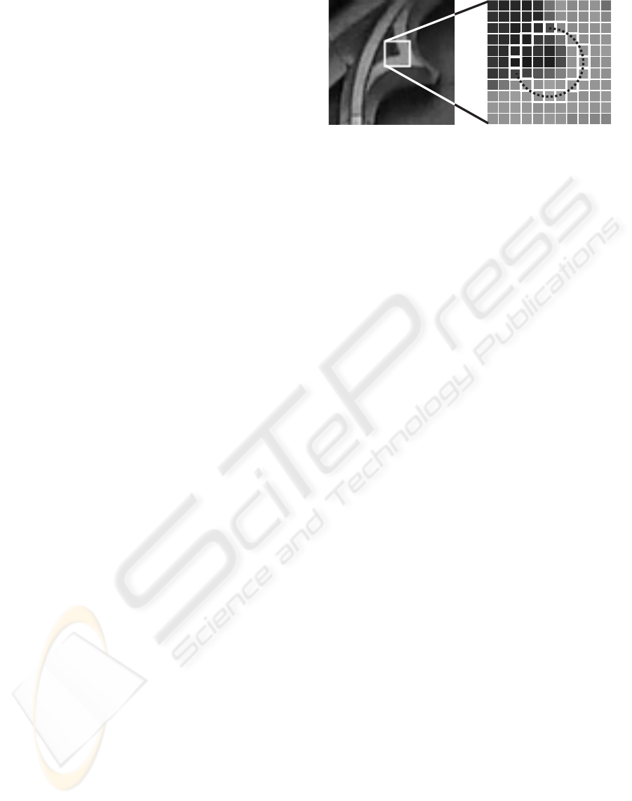
Figure 1: The illustration of segment test. The pixels 1
through 16 form the Bresenham circle. The contiguous
segment of pixels satisfying the thresholding condition is
marked with the dashed line.
dependenton a threshold, but many of the widelyused
corner detectors are also threshold-dependent. The al-
gorithm can also respond to single-pixel-wide lines at
certain angles, when the quantisation of the Bresen-
ham circle misses the line.
2 THE FAST ALGORITHM
In order to indicate whether the pixel p with a specific
intensity value I
p
is a corner, the FAST detector ana-
lyzes a 16 pixel Bresenham circle surrounding p. The
Bresenham circle is an approximation of the circle,
drawn on a raster)see figure 1. The positive detection
is declared if n points of this circle form a contiguous
segment which is either darker than the center point
minus a given threshold t, or brighter than the center
point plus the threshold (see figure 1).
Direct application of this criterion turned out to be
ineffective, thus to improve the performance n is set
to 12 in the first version of the algorithm, and an ad-
ditional, coarse test was executed. During the coarse
test, four pixels lying on the main compass directions
(indexed 1, 5, 9 and 13) are analyzed. The reason for
this is that any 12-pixels arc on the tested circle in-
cludes 3 of those points. Only if at least 3 of them are
darker than I
p
− t or brighter than I
p
+ t, the appro-
priate corner candidate p is tested thoroughly. This
approachenables discarding many candidates quickly
and reduces effectively the image processing time.
The coarse test improves the detector’s performance,
however it has several weaknesses. The main dis-
advantage is that it is not valid for n < 12. More-
over, the choice of the 4 examined points involves
assumptions about the features’ appearance distribu-
tions and the information gained on this stage of pro-
cessing is discarded. To eliminate these flaws Rosten
and Drummond created the decision tree using the
ID3 algorithm on the samples acquired with the di-
rect segment test (Rosten and Drummond, 2006). To
HIGH-SPEED IMAGE FEATURE DETECTION USING FPGA IMPLEMENTATION OF FAST ALGORITHM
175
reduce the occurrence of adjacent positive responses,
the non-maximal suppression is applied. As the seg-
ment test is a Boolean function, an additional mea-
sure is needed. The corner score function V, defined
as the sum of absolute differences between central
point’s intensity and intensities of pixels on the con-
tiguous arc, is introduced. Corner score for all pos-
itive responses is computed and those with V lower
than its neighbors are discarded. Let us denote the
pixels brighter than brighter than I
p
+t by S
bright
, and
the pixels darker than I
p
− t by S
dark
. The complete
equation for corner score is given in equation 1.
V = max(
∑
x∈Sbright
|I
p→x
− I
p
|−t,
∑
x∈Sdark
|I
p
− I
p→x
|−t)
(1)
As mentioned before, our hardware architecture
does not perform any coarse test before actual corner
detection; it also does not employ the decision tree.
Instead, an exhaustive search is performed for all the
image pixels. Because the FPGA can perform com-
putations in parallel, such approach has no negative
effect on the performance.
3 THE HARDWARE
ARCHITECTURE
To process data in parallel, the designed architec-
ture requires to have simultaneous access to all pix-
els under investigation (the 16 pixels placed on the
Bresenham circle and the central pixel). This re-
quires constant access to a 7× 7 processing window.
To achieve this goal, 6 BlockRAM memories along
with read/write address generation logic were used as
FIFO delay buffers. The FIFO depth is equal to the
horizontal resolution of the image. Additionally, 49
8-bit registers were used to store pixel intensity val-
ues in the investigatedwindow. Theseintensity values
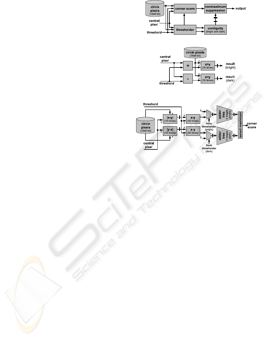
are then passed to the processor. The block diagram,
along with more detailed view on selected modules of
the processor, is given in figure 2.
The design is divided into modules: the thresh-
older, the contiguity module, the corner score mod-
ule and the non-maximum suppression module. The
thresholder module computes whether or not the pix-
els on the Bresenham circle have the intensity value
greater than the center pixel intensity value plus
threshold (‘bright’ pixels), or lower than the center
pixel intensity value minus threshold (‘dark’ pixels).
The output of this module is ‘1’ if the condition is sat-
isfied, and ‘0’ if not, and forms two 16-bit wide logic
vectors. The overall latency for this module is 1 clock
cycle. The corner score module computes the corner
(a) Block diagram
(b) Thresholder module
(c) corner score module
Figure 2: Block diagram of the architecture and selected
modules. Thick bars across datapaths indicate the pipeline
registers.
score according to equation 1. In the first clock cycle,
for each pixel the absolute value of the differences
between the pixels on the Bresenham circle and the
center pixel (for the ‘bright’ pixels) and also the abso-
lute value of the differences between the center pixel
and the pixelson the Bresenham circle (for ‘dark’ pix-
els) is computed. This gives two groups of results,
each one of them composed of 16 values. In the next
clock cycle, the threshold value is subtracted from all
of these values. Depending on the results from the
thresholder block, the values from the two groups are
passed to their respective adder tree (one for ‘bright’
pixels and one for ‘dark’ pixels). If the bit in the
thresholder output is set, the corresponding value is
passed unchanged, otherwise it is replaced with zero.
The adder trees are pipelined, to keep the delays at
minimum. In the final stage, the greater value from
the adder trees’ output is selected as the corner score.
The overall delay for this module is seven clock cy-
cles. The contiguity processor is the module which
monitors if there are n contiguous ‘bright’ of ‘dark’
pixels in the Bresenham circle surroundingthe central
pixel. The moduleoperates on the thresholder module
output. According to (Rosten and Drummond, 2006),
VISAPP 2008 - International Conference on Computer Vision Theory and Applications
176
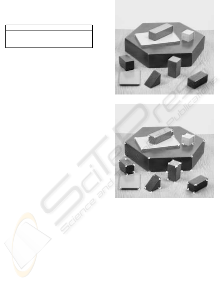
Table 1: Resource usage of the implemented design. The
values in percent are given with respect to all corresponding
resources available.
Parameter Value
No. of block RAMs 12 (100%)
No. of flipflops 1547 (40%)
No. of LUTs 2368 (62%)
the best choice for n is 9, so the contiguity check for
each group is implemented as 16 9-input logical AND
functions. The results are then OR-ed, and the output
of ‘1’ corresponds to the potential corner presence.
This output, along with the corner score are passed
to the nonmaximum suppression (NMS) module. To
provide simultaneous access to the pixel under inves-
tigation and its 5 × 5 neighborhood, four BlockRAM
memories have been used as FIFO delay buffers. The
delay of the NMS stage is 4 clock cycles, so the over-
all delay introduced by the procesor is 12 line-scans
plus 11 clock cycles (the pipeline depth). To equalise
the delays introduced by different modules, adding of
some additional registers to delay the signals was nec-
essary. After filling the pipeline, the processor accepts
and outputs one byte of data on every clock cycle.
4 IMPLEMENTATION AND
PERFORMANCE EVALUATION
The described architecture was implemented in hard-
ware for testing. The processor was implemented us-
ing VHDL as hardware description language together
with Xilinx’s ISE 8.1 package and Mentor Graphics’
ModelSim XE III 6.1e. The design was targeted at the
FPGA’s from Xilinx’s Spartan 3 family, namely the
XC3S200-4 (slower speed grade). First stage of test-
ing was to provethe circuit’s correctoperation by sim-
ulating the behavioral and post place and route model.
Upon successful test completion, the design was im-
plemented in a physical device. We have used the
Xplorer script from Xilinx to determine the best im-
plementation settings with the maximum clock speed
chosen as the priority. The resulting images are given
in figures 3 and 4.
The design consumes 62% of available FPGA re-
sources (in terms of look-up tables (LUT)) and is
capable of achieving clock frequencies of up to 130
MHz, using (see table 1).
This corresponds to the throughput of nearly 500
frames per second for a 512×512, 8-bit grayscale im-
(a) Original ‘blocks’ test image
(b) The ‘blocks’ image with superimposed detected cor-
ners
Figure 3: ‘Blocks’ test image processed using the imple-
mented hardware corner detection processor, t = 35, n = 9.
age. For a real, physical circuit the maximum fre-
quency would be about 10% lower (taking into ac-
count such phenomena like clock jitter), but this pro-
cessor is still capable to detect image corners in real-
time, even though it has been implemented in a small,
low end, slower speed grade FPGA. The speed is
about 30% lower than that of the implementation pre-
sented in (Rosten and Drummond, 2006), but the cost,
size and power consumption of the hardware architec-
ture are many times lower. Additionally, the remain-
ing FPGA resources may be used to perform addi-
tional image filtering or processing in parallel. This
HIGH-SPEED IMAGE FEATURE DETECTION USING FPGA IMPLEMENTATION OF FAST ALGORITHM
177
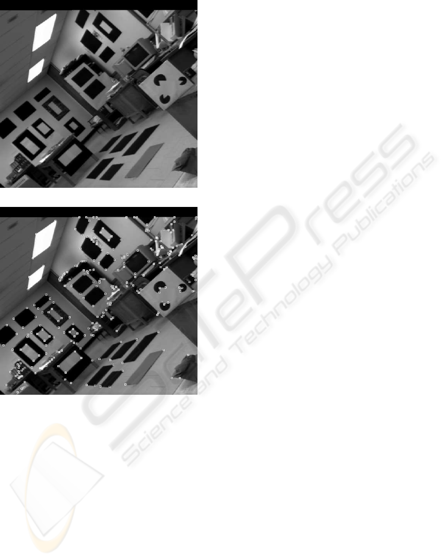
(a) Original ‘lab’ test image
(b) The ‘lab’ image with superimposed detected corners
Figure 4: ‘Lab’ test image processed using the implemented
hardware corner detection processor, t = 35, n = 9.
would result in an additional performance increase
over the software-oriented image processing algo-
rithm implementations. If the processing speed is crit-
ical, the architecture can easily be ported to a faster
FPGA – this would increase the procesing speed by
a factor of two. The implemented algorithm allows
to keep resource usage at a low level as compared
with other corner detectors that were implemented in
hardware. For example, the architecture presented in
(Cabani and MacLean, 2006) occupies 99% of the
79,040 logic elements (4-input look-up tables), which
is about 33 times more than the resource count for
our solution. Additionally, this complex design makes
also extensive use of many other FPGA resources
(344 multipliers and 230 RAM-based buffers). Please
note, that the architecture presented in this paper has
been implemented and tested on a physical device,
while the authors of (Cabani and MacLean, 2006)
describe a proposed architecture which has not been
implemented. In (Torres-Huitzil and Arias-Estrada,
2000), the authors present a compact implementation
of the SUSAN edge and corner detection algorithm
(Smith and Brady, 1997). It uses about two times less
resources than our solution. Please note however, that
it does not employ a non-maximumsuppression block
(which results in non-exact feature localization). Ad-
ditionally, the results presented in (Rosten and Drum-
mond, 2006) show, that the performance of SUSAN
detector (in terms of repeatability of features detected
in different views) is worse than the performance of
FAST, unless we have to deal with images corrupted
by strong noise.
5 CONCLUSIONS
In this paper we presented a fully functional hard-
ware implementation of the FAST corner detection
algorithm. The chosen corner detector is conceptu-
ally simple, which results in a compact implementa-
tion. The design is capable of meeting the demands
of real-time applications, as it can operate with the
speed of hundreds of frames per second without . The
use of FPGA circuits reduces the cost, size and power
consumption of the device and offers the flexibility
to modify definition of features and let to incorpo-
rate new features in new hardware revisions. Further
research will be focused on the optimization of the
data flow (eg. by adding additional pipeline stages
in the datapath, reusing the logic etc.). This should
result in further processing speed increase. The cor-
ner detection processor, along with the edge-detection
processor presented in (Kraft and Kasi´nski, 2007) are
planned to be parts of high-performance system for
tracking objects in high performance machine vision
applications, as well as for SLAM and visual odome-
try applications in robot vision. Such processor, oper-
ating directly on the image-data stream, can be incor-
porated into the system immediately after the camera,
forming a high-performance,compact machine vision
solution.
REFERENCES
Cabani, C. and MacLean, W. J. (2006). A proposed
pipelined-architecture for fpga-based affine-invariant
VISAPP 2008 - International Conference on Computer Vision Theory and Applications
178

feature detectors. In CVPRW ’06: Proceedings of
the 2006 Conference on Computer Vision and Pattern
Recognition Workshop, page 121, Washington, DC,
USA. IEEE Computer Society.
Deriche, R. and Giraudon, G. (1993). A computational ap-
proach for corner and vertex detection. International
Journal of Computer Vision, 10(2):101–124.
Harris, C. and Stephens, M. (1988). A combined corner and
edge detection. In Proceedings of The Fourth Alvey
Vision Conference, pages 147–151.
Kitchen, L. and Rosenfeld, A. (1982). Gray level corner
detection. Pattern Recognition Letters, 1(2):95–102.
Kraft, M. and Kasi´nski, A. (2007). Morphological edge de-
tection algorithm and its hardware implementation. In
Advances in Soft Computing, Computer Recognition
Systems 2 – CORES 2007: 5th International Confer-
ence on Computer Recognition Systems, volume 45,
pages 132–139.
Mokhtarian, F. and Suomela, R. (1998). Robust image cor-
ner detection through curvature scale space. IEEE
Transactions on Pattern Analysis and Machine Intel-
ligence, 20(12):1376–1381.
Moravec, H. (1979). Visual mapping by a robot rover. In
Proceedings of the 6th International Joint Conference
on Artificial Intelligence, pages 599–601.
Rosten, E. and Drummond, T. (2005). Fusing points and
lines for high performance tracking. In IEEE Inter-
national Conference on Computer Vision, volume 2,
pages 1508–1511.
Rosten, E. and Drummond, T. (2006). Machine learning for
high-speed corner detection. In European Conference
on Computer Vision, volume 1, pages 430–443.
Smith, S. M. and Brady, J. M. (1997). Susan – a new ap-
proach to low level image processing. International
Journal of Computer Vision, 23(1):45–78.
Torres-Huitzil, C. and Arias-Estrada, M. (2000). An fpga
architecture for high speed edge and corner detection.
In CAMP ’00: Proceedings of the Fifth IEEE Interna-
tional Workshop on Computer Architectures for Ma-
chine Perception (CAMP’00), page 112, Washington,
DC, USA. IEEE Computer Society.
Tsai, D. (1997). Boundary-based corner detection using
neural networks. Pattern Recognition, 30(1):85–97.
Wang, H. and Brady, M. (1995). Real-time corner detection
algorithm for motion estimation. Image Vision Com-
put., 13(9):695–703.
HIGH-SPEED IMAGE FEATURE DETECTION USING FPGA IMPLEMENTATION OF FAST ALGORITHM
179
