
ENHANCED
PHASE–BASED DISPLACEMENT ESTIMATION
An Application to Facial Feature Extraction and Tracking
Mohamed Dahmane and Jean Meunier
Diro, Universit
´
e de Montr
´
eal, CP 6128, Succursale Centre-Ville
2920 Chemin de la tour, Montr
´
eal, Qu
´
ebec, Canada, H3C 3J7
Keywords:
Facial feature extraction, Facial analysis, Gabor wavelets, Tracking.
Abstract:
In this work, we develop a multi-scale approach for automatic facial feature detection and tracking. The
method is based on a coarse to fine paradigm to characterize a set of facial fiducial points using a bank of
Gabor filters that have interesting properties such as directionality, scalability and hierarchy. When the first
face image is captured, a trained grid is used on the coarsest level to estimate a rough position for each facial
feature. Afterward, a refinement stage is performed from the coarsest to the finest (original) image level to get
accurate positions. These are then tracked over the subsequent frames using a modification of a fast phase–
based technique. This includes a redefinition of the confidence measure and introduces a conditional disparity
estimation procedure. Experimental results show that facial features can be localized with high accuracy and
that their tracking can be kept during long periods of free head motion.
1 INTRODUCTION
The computer vision community is interested in the
development of techniques to figure out the main el-
ement of facial human communication in particular
for HCI applications or, with additional complexity,
meeting video analysis. In both cases, automatic fa-
cial analysis is highly sensitive to face tracking per-
formance, a task which is rendered difficult due prin-
cipally to environment changes and particularly to its
great appearance variability under different head ori-
entations, its non–rigidity adds yet another degree of
difficulty. To overcome these problems, a great num-
ber of techniques have been developed which can be
divided into four categories: knowledge–, feature–,
template– and appearance–based (Yang, 2004).
Among these techniques, it is known that face analy-
sis by feature point tracking demonstrates high con-
current validity with manual FACS (Facial Action
Coding System) coding (Cohen et al., 1999), which
is promising for facial analysis (Cottrell et al., 2003).
Moreover, when facial attributes are correctly ex-
tracted, geometric feature–based methods typically
share some common advantages, such as explicit
face structure, practical implementation, collaborative
feature-wide error elimination (Hu et al., 2004). In
this context, several concepts were developed.
The classical matching technique extracts features
from two frames and tries to establish a correspon-
dence, whereas correlation-based techniques com-
pare windowed areas in two frames, and the maxi-
mum cross correlation value provides the new rela-
tive position. However, recent techniques have been
developed to determine the correct relative position
(disparity
1
) without any searching process as it is
required by the conventional ones. In this cate-
gory, phase–based approaches have attracted atten-
tion because of their biological motivation and robust-
ness (Theimer and Mallot, 1994; Fleet and Jepson,
1993).
In the literature, one can find several attempts
at designing non–holistic methods based on Gabor
wavelets (Shen and Bai, 2006). Due to their interest-
ing and desirable properties including spatial locality,
self similar hierarchical representation, optimal joint
uncertainty in space and frequency as well as biolog-
ical plausibility (Flaton and Toborg, 1989). However,
1
we
use interchangeably the words ”disparity” and ”dis-
placement”
427
Dahmane M., Meunier J. and Meunier J. (2008).
ENHANCED PHASE–BASED DISPLACEMENT ESTIMATION - An Application to Facial Feature Extraction and Tracking.
In Proceedings of the Third International Conference on Computer Vision Theory and Applications, pages 427-433
DOI: 10.5220/0001081804270433
Copyright
c
SciTePress
most of them are based on the magnitude part of the
filter response (Lades et al., 1993; Tian et al., 2002;
Liu and Wechsler, 2003; Valstar and Pantic, 2006). In
fact, under special consideration, particularly because
of shift–variant property, the Gabor phase can be a
very discriminative information source (Zhang et al.,
2007).
In this paper, we use this property of Gabor phase
for facial feature tracking. In section 2, we describe
the Gabor-kernel family we are using. In section 3,
we introduce the adopted strategy for facial features
extraction. The tracking algorithm is given in section
4, including technical details and a discussion on its
derivation. Finally, we apply the approach to a facial
expression database, in section 5.
2 LOCAL FEATURE MODEL
BASED ON GABOR WAVELETS
2.1 Gabor Wavelets
A Gabor jet J(x) describes via a set of filtering opera-
tion (eq. 1), the spatial frequency structure around the
pixel x, as a set of complex coefficients.
J
j
(x) =
Z
N
2
I(x
0
)Ψ
j
¡
x − x
0
¢
dx
0
(1)
A Gabor wavelet is a complex plane wave modulated
by a Gaussian envelope:
Ψ
j
(x) = η
j
e
−
kk
j
k
2
kxk
2
2σ
2
·
e
ık
j
·x
− e
−
σ
2
2
¸
(2)
where σ = 2π, and k
j
= (k
jx
,k
jy
) =
(k
ν
cos(φ
µ
),k
ν
sin(φ
µ
)) defines the wave vector,
with
k
ν
= 2
−
ν+2
2
π and φ
µ
= µ
π
8
Notice that the last term of equation 2 compensates
for the non-null average value of the cosine compo-
nent. We choose the term η
j
so that the energy of the
wavelet Ψ
j
is unity (eq. 3).
Z
N
2
¯
¯
Ψ
j
(x)dx
¯
¯
2
= 1 (3)
A jet J(x) = {a
j
e
ıφ
j
/ j = µ +8ν}, is commonly de-
fined as a set of 40 complex coefficients constructed
from different Gabor filters spanning different orien-
tations (µ ∈ [0,7]) under different scales (ν ∈ [0,4]).
3 AUTOMATIC VISUAL
ATTRIBUTE DETECTION
3.1 Rough Face Localization
When the first face image is captured, a pyramidal
image representation is created, where the coarsest
level is used to find near optimal starting points for
the subsequent individual facial feature localization
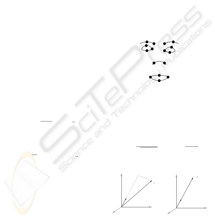
stage. Each trained grid (Fig. 1) from a set of pre-
stored face grids is displaced as a rigid object over the
image. The grid position that maximizes the weighted
magnitude–based similarity function (eq. 4 and 5)
provides the best fitting node positions.
1.2
1.1
2.1
2.2
2.3
3.1 3.2
4.1
4.2
4.3
5.1 5.2
6.1
6.2
6.4
6.3
Figure 1: Facial nodes with their respective code.
Sim(I,G) =
L
∏
l
S(J
l
,J
0
l
) (4)
S(J,J
0
) refers to the similarity between the jets of the
corresponding nodes (eq. 5), L stands for the total
number of nodes.
S(J, J
0
) =
∑
j
c
j
a
j
a
0
j
q
∑
a
j
2
∑
a
0
j
2
with c
j
=
1 −
¯
¯
¯
a
j
− a
0
j
¯
¯
¯
a
j
+ a
0
j
2
(5)
The role of the weighting factor c
j
is to model the
amplitude–distortion δ as illustrated in figure 2.
δ
δ
a
a
a
a
Figure 2: Two different 3–dimensional jets. In the right sub-
figure, a not–weighted amplitude–based similarity S(J,J
0
)
would have given an incorrect perfect match value 1..
VISAPP 2008 - International Conference on Computer Vision Theory and Applications
428
3.2 Local Facial Feature Position
Refinement
The rough facial grid-node positions are then inde-
pendently refined by estimating the displacement us-
ing a hierarchical selective search. The calculated
displacements are propagated to subsequent hierarchy
level, and a refinement operation is again performed.
The optimal displacements are, finally, given at the
finest image level.
The selective local search can be described as a
local 3 × 3 neighborhood search, which allows dis-
torting the grid until the maximum similarity value is
reached. The search is then refined by propagating, to
the next finer level, the three positions giving the high-
est similarity values. For each propagated potential
position P(x,y) the three adjacent neighboring posi-
tions P(x+1,y),P(x,y+1) and P(x+1,y+1) are also
explored. The selective search continues downward
until the finest level of the pyramid image is reached,
where the optimal position is maximum (eq. 5).
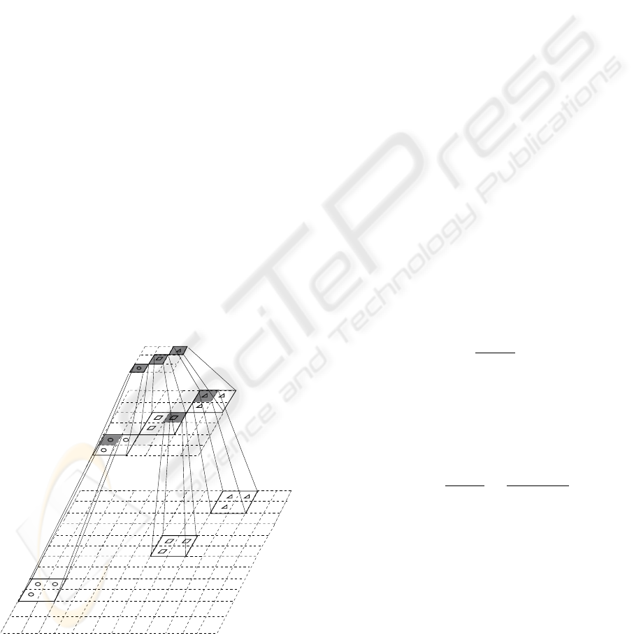
This procedure permits to decrease the inherent
complexity required to calculate the convolution un-
der an exhaustive search, first by reducing the search
area (e.g. a 12 × 12 neighborhood on the finest level
will correspond only to a 3 × 3 on the coarsest one)
(Fig. 3), and second by using smaller–size jets in
coarser levels.
9/144
9/36
9/9
Figure 3: Hierarchical–selective search. The values in left
side denote the number of explored positions vs. the total
number that would be explored in the case of an exhaustive
search.
4 FACIAL ATTRIBUTES
TRACKING
Facial features tracking is performed by estimating
a displacement d via a disparity estimation tech-
nique (Theimer and Mallot, 1994), that exploits the
strong variation of the phases of the complex filter re-
sponse (Maurer and von der Malsburg, 1996).
Later adopted by (Zhu and Ji, 2006), this frame-
work investigated in (Maurer and von der Malsburg,
1996; Wiskott et al., 1997) is based on the maximiza-
tion of a phase–based similarity function which is
nothing else than a modified way to minimize the
squared error, within each frequency scale ν given
two jets J and J
0
(eq. 6), as it has been proposed
in (Theimer and Mallot, 1994).
e
2
ν
=
∑
µ
c
ν,µ
(∆φ
ν,µ
− k
ν,µ
· d
ν
)
2
(6)
However, we assume that the merit of that framework
is the use of a saliency term (eq. 7) as weighting factor
c
ν,µ
, privileging displacement estimation from filters
with higher amplitude response. Also, for such re-
sponse it seems that phase is more stable (McKenna
et al., 1997).
c
j
= a
j
a
0
j
(7)
In (Theimer and Mallot, 1994), the weighting factor
c
j
represents a confidence value (eq. 8), that assesses
the relevance of a single disparity estimate, and tends
to reduce the influence of erroneous filter responses.
c
j
= 1 −
¯
¯
¯
a
j
− a
0
j
¯
¯
¯
a
j
+ a
0
j
(8)
Both saliency term and normalized confidence ignore
the phase of the filter response. In the present work,
we try to penalize the response of the erroneous fil-
ters by using a new confidence measure that combines
both amplitude and phase (eq. 9).
c
j
= a
j
2
1 −
¯
¯
¯
a
j
− a
0
j
¯
¯
¯
a
j
+ a
0
j
2
π
−
¯
¯
¥
∆
φ
j
¦
2π
¯
¯
π
(9)
The first term in this formulation represents the
saliency term that is incorporated as a squared value
of only the amplitude of the reference jet J which –
contrary to the probe jet J
0
– necessarily ensures high
confidence. We mean here by the reference jet the
jet calculated from the previous frame or even a pre-
stored one. The second bracket squared-term holds
the normalized magnitude confidence. While, the last
term, where
¥
∆φ
j
¦
2π
denotes the principal part of the
phase difference within the interval [−π,π), allows
giving more weight to filters where the phase differ-
ence has a favorable convergence while, at the same
time, limiting the influence of outlier filters.
ENHANCED PHASE–BASED DISPLACEMENT ESTIMATION - An Application to Facial Feature Extraction and
Tracking
429

The displacements can then be estimated with
sufficient accuracy by minimizing (eq. 6) which leads
to a set of linear equations for d, that can be directly
resolved from (eq. 10).
d(J, J
0
) =
µ
∑
j
c
j
k
jx
2
−
∑
j
c
j
k
jx
k
jy
−
∑
j
c
j
k
jx
k
jy
∑
j
c
j
k
jy
2
−1
µ
∑
j
c
j
k
jx
¥
∆φ
j
¦
2π
∑
j
c
j
k
jy
¥
∆φ
j
¦
2π
(10)
4.1 Iterative Disparity Computation
In (Theimer and Mallot, 1994), to obtain the disparity
within one scale, the feature displacement estimates
for each orientation were combined into one displace-
ment per scale (d
ν
) using the least squared error crite-
rion (eq. 6). The optimal disparity is then calculated
by a combination of these estimates as an average
value over all scales with appropriate weights (eq. 8).
Whereas in various approaches, a least squared solu-
tion is obtained in one pass, over the overall consid-
ered frequencies (Wiskott et al., 1997), some of them
propose at first to use the lower frequencies subset
(e.g. ν ∈ [2, 4]), and then to resolve for higher fre-
quencies subset (e.g. ν ∈ [0,2]).
These resolutions may carry an additive risk of un-
favorable results; that is knowing that at each scale,
there exists a displacement value above which its es-
timation would not be reliable, due to the lack of a
large overlap of the Gabor kernels. Obviously, this
value depends on the radius (σ/k
ν
) of the Gaussian
envelope.
As the power spectrum of the Gabor signal (eq. 2)
is concentrated in the interval [−σ/ (2k
ν
),σ/(2k
ν
)],
we can compute the maximum disparity d
max
ν
that can
be estimated within one scale (eq. 11).
d
max
ν
=
σ
2k
ν
=
π
k
ν
(11)
If for example the true displacement is d = 7 pixels,
then according to the Gabor–kernel family we used
(section 2.1), only the lowest frequency band filter
gives a reliable estimation of the disparity.
So, the trick consists in estimating the disparity itera-
tively, from the lowest frequency to a highest critical
frequency, depending on a stopping criterion involv-
ing the maximum allowed disparity value that can be
effectively estimated. Some values are shown in ta-
ble 1 as a function of scale.
Given J(x) = {a
j
e
ıφ
j
} the reference jet and
J
0
(x + d) = {a
0
j
e
ıφ
0
j
} the probe jet i.e. the jet
calculated at the probe position (x + d), using
Table 1: Critical displacement for each frequency.
ν 0 1 2 3 4
d
max
ν
(pixel) 2 ≈ 3 4 ≈ 6 8
the j
th
wavelet, an iterative disparity estimation
algorithm (Fig. 4) gives the optimal displacement
d
opt
, that makes the two jets the most similar possible.
Algorithm 1. ITERATIVEDISPARITYESTIMATION (x)
1
Initially set
ν
with the lowest
frequency index;
2
Calculate
J
0
ν
(x)
for the components that
refer to
ν
at different orientations;
3
Estimate the disparity
δd
using
equation (10) by considering all the
processed frequencies at different
orientations;
4
Compensate for the phase
φ
0
j
=
¥
φ
0
j
− k
j
· δd
¦
2π
;
5
Cumulate the disparity
d = d +δd
;
6
Perform the convergence test, if
δd
is
greater than a threshold goto (3);
7
If the stopping criterion is not met,
i.e. the overall displacement
d
is
less than the critical displacement
value
d
max
ν
, see Table (1), then put
ν = ν +1
(the next higher frequency)
and goto (2).
Figure 4: Conditional iterative disparity estimation algo-
rithm.
Iteratively, the conditional iterative disparity estima-
tion (Fig. 4) will unroll on the novel position x
new
←
x + d
opt
until a convergence criterion is achieved i.e.
d
opt
tends to 0 or the maximum number of iterations
l
max
iter
is reached. Herein, ν
critic
could keep its previ-
ous value, instead of starting, for each new position,
with the coarsest scale (i.e. ν
critic
= N
f
− 1).
5 EXPERIMENTAL RESULTS
The Hammal–Caplier face database (Hammal et al.,
2007) is used to test the proposed approach. In this
database, each video contains about 120 frames for
each of the 15 distinct subjects that are acting differ-
ent facial expressions (neutral, surprise, disgust and
joy) with some tolerance on rotation and tilting. We
used 30 videos with spatial resolution of (320 × 240).
VISAPP 2008 - International Conference on Computer Vision Theory and Applications
430
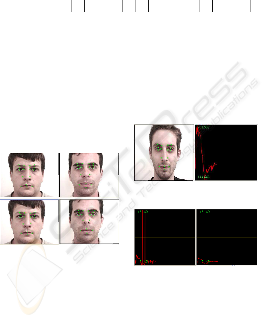
Table 2: Percentage of used frames to handle local facial deformations.
facial feature 1.1 1.2 2.1 2.2 2.3 3.1 3.2 4.1 4.2 4.3 5.1 5.2 6.1 6.2 6.3 6.4
(%) of used frames 2.5 1.8 3.9 4 3 2.3 3.4 4.2 3.7 2.7 1.5 2.4 3.8 8 2 9
A generic face grid (Fig. 1) is created using one frame
from each subject (frontal view). In order to handle
the facial deformation and prevent drifting, facial fea-
ture bunches are generated. Table 2 shows each land-
mark and the percentage of the total number of frames
required to create its own representative facial bunch.
As we can see the number increases with the degree
of variability of the local deformation that can be ob-
served for each facial feature. These percentages were
set empirically.
To locate the face grid, a search is performed over
the coarsest level of the 3 image-levels that we used.
Then a hierarchical selective refinement is performed
using a weighted magnitude–based similarity to get
the optimal node positions. Figure 5 shows the results
corresponding to the position refinement after rough
node positioning.
Figure 5: Nodes position refinement (bottom) after rough
positioning (top).
Figure 6 shows the magnitude profile corresponding
to (µ,ν) = (0,0) for node 2.1 (right inner–eye) from
a video where the subject is performing a disgust ex-
pression. Figure 7 illustrates the phase profile of the
same subject with and without phase compensation
(φ
0
j
←
j
φ
0
j
− k
j
· d
l
k
2π
) in Algorithm 1.
One can observe some large and sharp phase varia-
tions when non compensation is used, corresponding
to tracking failure.
Figure 8 shows three shots of a video showing a sub-
ject performing a disgust expression, the top subfig-
ure presents the last frame. In this figure, we can see
that the tracking has failed with a single jet (instead
of a bunch). It’s easy to see that the drifting can not
be measured from the magnitude profile only (middle
row), because the magnitude changes smoothly with
the position. This is not the case for the phase (bot-
tom row) which is shift–variant, however by using a
shift–compensation and facial bunches as described
in Algorithm 1, we can correctly track the facial land-
marks (Fig. 9). In comparison with figure 8, the bot-
tom graph shows a horizontal and correct phase pro-
file (without node drifting). The reader can appreciate
the impact of such correction by looking in particular
at node
Figure 6: Amplitude profile over time of Node 2.1 (right
inner–eye).
Figure 7: phase profile : not–corrected (left) vs. corrected
(right) phase.
2.1 (right inner–eye) and 2.3 (right lower eyelid) in
figures 8 and 9.
In table 3, we summarize the tracking results of
16 facial features of 10 different persons with differ-
ent expressions. The mean error of node positions
using the proposed approach is presented in pixels.
From the last column, we can see how the use of fa-
cial bunches appreciably increases nodes positioning
and consequently the tracking accuracy.
ENHANCED PHASE–BASED DISPLACEMENT ESTIMATION - An Application to Facial Feature Extraction and
Tracking
431
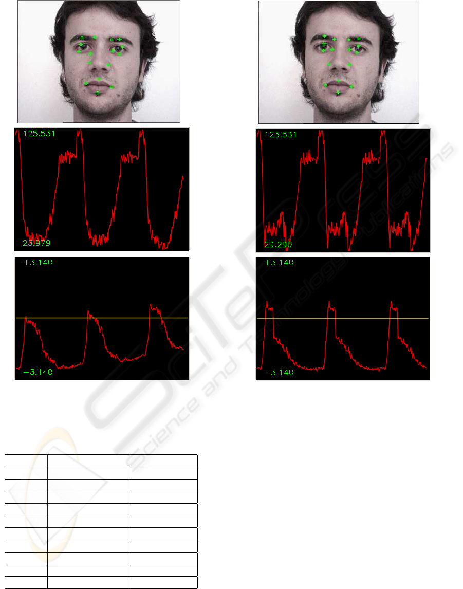
Figure 8: A drifting case : Magnitude vs. Phase profile.
Table 3: Mean position error (pixels).
.
Subject Without bunches With bunches
#1 4.28 1.78
#2 3.98 1.37
#3 5.07 2.03
#4 4.44 1.9
#5 4.17 1.7
#6 4.05 1.63
#7 4.69 1.5
#8 4.1 1.75
#9 5.85 2.49
#10 6.93 2.47
Figure 9: Drift avoidance.
6 CONCLUSIONS
In this work, we present a modification of a phase–
based displacement estimation technique using a new
confidence measure and a conditional disparity es-
timation. The proposed tracking algorithm permits
to eliminate accumulation of tracking errors to avoid
drifting, so offering a good facial landmark localiza-
tion, which is a crucial task in a feature–based fa-
cial expression recognition system. We notice that
in these experiments, excepts for the first frame, no
geometry constraints were used to enforce the facial
shape configuration, especially for features that are
difficult to track.
More training sessions could be needed to obtain
pre-stored grids and features bunches that are rep-
VISAPP 2008 - International Conference on Computer Vision Theory and Applications
432

resentative of the variability of the human face ap-
pearance for initialisation and tracking respectively.
In this context, through available face databases, ad-
vanced statistical models of data can be obtained
using learning algorithms, such as EM (Jiao et al.,
2003).
To reinforce the refinement step we are working
on improving the local structure by providing an al-
ternative appearance model which focuses more on
high frequency domain without necessarily altering
the relevant low frequency texture information, in-
stead of modeling the grey level appearance (Zhang
et al., 2003) or exploiting the global shape con-
straint (McKenna et al., 1997) which tends to smooth
out important details.
As future work, we plan to use facial feature bunches
to generate for each facial expression and for each
facial attribute what could constitute ”Expression
Bunches” for facial expression analysis.
ACKNOWLEDGEMENTS
This research was supported by the National Sci-
ences and Engineering Research Council (NSERC) of
Canada.
REFERENCES
Cohen, J., Zlochower, A., Lien, J., and Kanade, T. (1999).
Face Analysis by Feature Point Tracking Has Concur-
rent Validity with Manual FACS Coding. Psychophys-
iology 36(1):35–43.
Cottrell, G., Dailey, M., and Padgett, C. (2003). Is All
Faces Processing Holistic? The view from UCSD. M.
Wenger, J Twnsend (Eds), Computational, Geometric
and Process Perspectives on Facial Recognition, Con-
texts and Challenges: Contexts and Challenges, Erl-
baum.
Flaton, K. and Toborg, S. (1989). An approach to image
recognition using sparse filter graphs. In International
Joint Conference on Neural Networks, (1):313–320.
Fleet, D. and Jepson, A. (1993). Stability of phase informa-
tion. In IEEE Trans. on PAMI, 15(12):1253–1268.
Hammal, Z., Couvreur, L., Caplier, A., and Rombaut, M.
(2007). Facial expression classification: An approach
based on the fusion of facial deformation unsing the
transferable belief model. In Int. Jour. of Approximate
Reasonning.
Hu, Y., Chen, L., Zhou, Y., and Zhang, H. (2004). Esti-
mating face pose by facial asymmetry and geometry.
In IEEE International Conference on Automatic Face
and Gesture Recognition.
Jiao, F., Li, S., Shum, H.-Y., and Schuurmans, D. (2003).
Face alignment using statistical models and wavelet
features. In Computer Vision and Pattern Recognition
(1) p. 321–327.
Lades, M., Vorbr
¨
uggen, J. C., Buhmann, J., Lange, J., von
der Malsburg, C., W
¨
urtz, R. P., and Konen, W. (1993).
Distortion invariant object recognition in the dynamic
link architecture. In IEEE Transactions on Computers
3(42):300–311.
Liu, C. and Wechsler, H. (2003). Independent component
analysis of gabor features for face recognition. In
IEEE Trans. on Neural Networks, (14):4, 919–928.
Maurer, T. and von der Malsburg, C. (1996). Tracking and
learning graphs and pose on image sequences of faces.
In 2nd International Conference on Automatic Face
and Gesture Recognition, p. 76.
McKenna, S., Gong, S., W
¨
urtz, R., Tanner, J., and Banin,
D. (1997). Tracking facial feature points with gabor
wavelets and shape models. In Proceedings of the
First International Conference on Audio– and Video–
based Biometric Person Authentication, 1206(3):35–
42. Springer Verlag.
Shen, L. and Bai, L. (2006). A review on gabor wavelets
for face recognition. In Pattern Analysis and Applica-
tions, (9):2,273–292.
Theimer, W. and Mallot, H. (1994). Phase–based binocular
vergence control and depth reconstruction using active
vision. In CVGIP: Image Understanding, 60(3):343–
358.
Tian, Y., Kanade, T., and Cohn, J. (2002). Evaluation of
gabor wavelet–based facial action unit recognition in
image sequences of increasing complexity. In In Proc.
of the 5th IEEE Int. Conf. on Automatic Face and Ges-
ture Recognition.
Valstar, M. and Pantic, M. (2006). Fully automatic facial ac-
tion unit detection and temporal analysis. In CVPRW,
p. 149.
Wiskott, L., Fellous, J., Kr
¨
uger, N., and von der Malsburg,
C. (1997). Face recognition by elastic bunch graph
matching. In IEEE Transactions on Pattern Analysis
and Machine Intelligence. 19(7):775–779.
Yang, M. (2004). Recent advances in face detection. In
Tutorial of IEEE Conferece on Pattern Recognition.
Zhang, B., Gao, W., Shan, S., and Wang, W. (2003). Con-
straint shape model using edge constraint and gabor
wavelet based search. In AVBPA03, 52–61.
Zhang, B., Shan, S., Chen, X., and Gao, W. (2007). His-
togram of gabor phase patterns (HGPP): A novel ob-
ject representation approach for face recognition. In
IEEE Tran. on Image Processing (16):1, pp.57-68.
Zhu, Z. and Ji, Q. (2006). Robust pose invariant facial
feature detection and tracking in real-time. In ICPR,
1092-1095.
ENHANCED PHASE–BASED DISPLACEMENT ESTIMATION - An Application to Facial Feature Extraction and
Tracking
433
