
MULTI-CAMERA DETECTION AND MULTI-TARGET
TRACKING
Traffic Surveillance Applications
R. Reulke
Humboldt-Universität zu Berlin, Institut für Informatik, Computer Vision, Unter den Linden, Berlin, Germany
S. Bauer, T. Döring, R. Spangenberg
German Aerospace Center, Institute of Transportation Systems, Rutherfordstr., Berlin, Germany
Keywords: Multi-camera sensing, fixed-viewpoint camera, cooperative distributed vision, multi-camera orientation,
multi-target tracking.
Abstract: Non-intrusive video-detection for traffic flow observation and surveillance is the primary alternative to
conventional inductive loop detectors. Video Image Detection Systems (VIDS) can derive traffic parameters
by means of image processing and pattern recognition methods. Existing VIDS emulate the inductive loops.
We propose a trajectory based recognition algorithm to expand the common approach and to obtain new
types of information (e.g. queue length or erratic movements). Different views of the same area by more
than one camera sensor are necessary, because of the typical limitations of single camera systems, resulting
from occlusions by other cars, trees and traffic signs. A distributed cooperative multi-camera system enables
a significant enlargement of the observation area. The trajectories are derived from multi-target tracking.
The fusion of object data from different cameras will be done by a tracking approach. This approach opens
up opportunities to identify and specify traffic objects, their location, speed and other characteristic object
information. The system creates new derived and consolidated information of traffic participants. Thus, also
descriptions of individual traffic participants are possible.
1 INTRODUCTION
An intelligent traffic management is based on an
exact knowledge of the traffic situation. Therefore
traffic monitoring at roads and intersections is an
essential prerequisite for the implementation of the
Intelligent Transportation System (ITS).
The most common detection and surveillance
systems to measure traffic flow on public roads are
inductive loops and microwave radar systems. An
analysis and a comparison of different sensors can
be consulted in (Klein et al., 1997).
VIDS using real time image processing
techniques (Michalopoulus, 1991), (Wigan, 1992),
(Kastrinaki et al., 2003), (Kumar et al., 2005) and
(Luo and Bhadarkar, 2005) became more attractive
in the last 15 years. Besides traditional traffic
parameters like presence, vehicle length, speed as
well as time gap between two vehicles they can also
determine congestion length, source-destination
matrices, blockage or accidents and estimate travel
times (Datta and Schattler, 2000), (Harlow and
Wang, 2001), (Setchell and Dagless, 2001) and
(Yung and Lai, 2001).
The multi-camera system was used to overcome
limitations of single camera systems (e.g.
occlusions) and to be able to enlarge the observation
area.
This paper is organized as follows: After an
overview of existing multiple-camera systems the
approach is introduced. Then, an example
installation is described and the results for this
installation are presented. It follows an application,
which adapts formerly derived traces or trajectories
of turning vehicles by hyperbolas. This analytical
description of trajectories can be used for traffic
scene description. The article closes with a summary
and an outlook.
585
Reulke R., Bauer S., Döring T. and Spangenberg R. (2008).
MULTI-CAMERA DETECTION AND MULTI-TARGET TRACKING - Traffic Surveillance Applications.
In Proceedings of the Third International Conference on Computer Vision Theory and Applications, pages 585-591
DOI: 10.5220/0001085705850591
Copyright
c
SciTePress
2 MULTIPLE-CAMERA
SYSTEMS (MCS) OVERVIEW
There already exist a variety of solutions for multi-
camera observation and tracking, especially for
surveillance tasks. The main problem to solve for a
MCS is that an observed object in the images of the
different cameras must be assigned to the same real
object. Therefore, an accurate relation between
every pixel and the object coordinates must be
available.
A real-time cooperative multi-target tracking
system for ITS-applications was presented by
(Matsuyama and Ukita, 2002). A system of active
vision agents (AVAs), where an AVA is a logical
model of a network-connected computer with an
active camera cooperatively track their target objects
by dynamically exchanging object information with
each other. With this cooperative tracking capability,
the system can track multiple moving objects
persistently even in complicated dynamic real world
environments. (Collins et al., 2002) have described a
system for acquiring multi-view videos of a person
moving through the environment. A real-time
tracking algorithm adjusts the pan, tilt, zoom and
focus parameters of multiple active cameras to keep
the moving person centred in each view. The output
of the system is a set of synchronized, time-stamped
video streams, showing the person simultaneously
from several viewpoints.
(Meagher et al., 2004) have presented a method
for tracking an object and the determination of its
absolute position using the image coordinates
provided from multiple cameras. The proposed
method obtains the image coordinates of an object at
known locations and generates “virtual points”.
(Mittal and Davis, 2001) have described an
algorithm for detecting and tracking people in a
cluttered scene using multiple synchronized
cameras. This camera arrangement results in
multiple wide-baseline camera systems. The results
from these wide-baseline camera systems are then
combined using a scheme that rejects outliers and
gives very robust estimations of the 2D locations of
the people.
3 APPROACH
The used cameras cover overlaid or adjacent
observation areas. With it, the same road user can be
observed from different cameras under different
positions and angles. Using automatic image
processing methods the objects of interest are found
in the image data. In order to enable the tracking and
fusion of the objects detected in the respective
observation area the image coordinates of these
objects are converted to a common world coordinate
system. In case of poor quality of the orientation
parameters, the same objects will be observed in
different places. To avoid misidentification of these
objects which were derived from different camera
images, high precision in coordinate transformation
of the image into the object space is required.
Therefore, a very exact calibration (interior
orientation) as well as knowledge of the position and
view direction (exterior orientation) of the camera is
necessary. If the camera positions are given in
absolute geographical coordinates, the detected
objects can be provide in world coordinates.
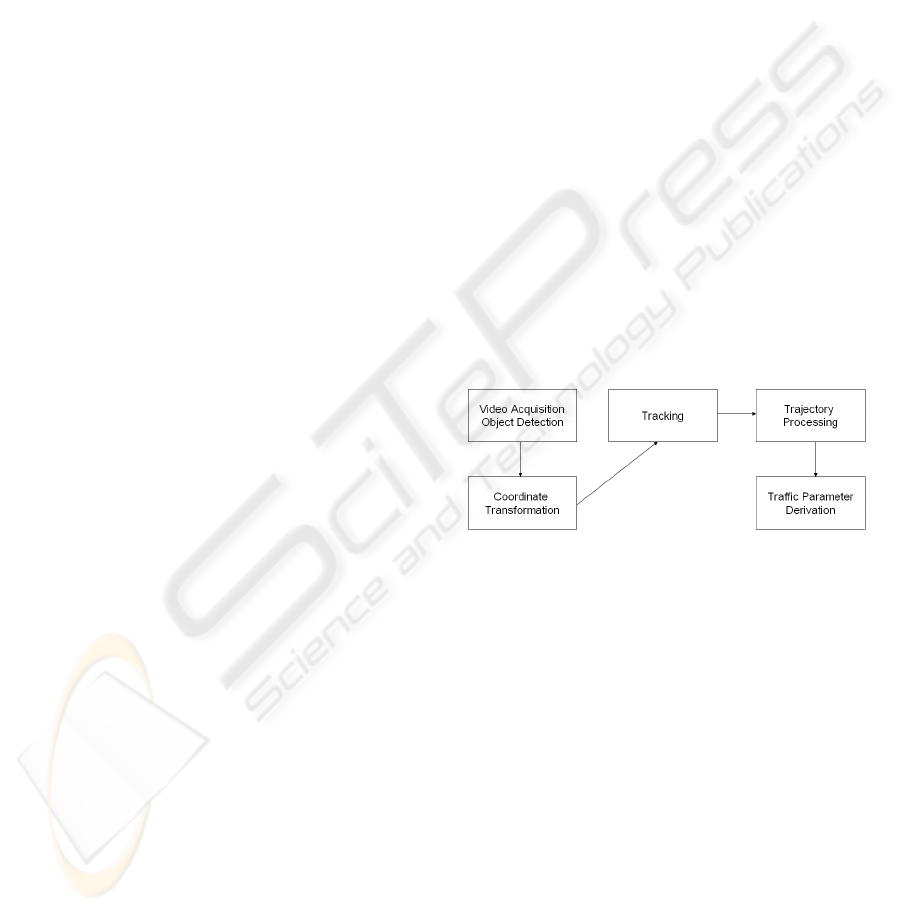
The approach presented here can be separated
into four steps (Figure 1). Firstly, all moving objects
have to be extracted from each frame of the video
sequence. Next, these traffic objects have to be
projected onto a geo-referenced world plane.
Afterwards these objects are tracked and associated
to trajectories. This can be utilized to assess
comprehensive traffic parameters and to characterize
trajectories of individual traffic participants.
Figure 1: Process chain.
These four steps are described more precisely below.
3.1 Video Acquisition and Object
Detection
In order to receive reliable and reproducible results,
only compact digital industrial cameras with
standard interfaces and protocols (e.g. IEEE1394,
Ethernet) are used.
To extract the traffic objects from an image
sequence, different image processing libraries or
programs (e.g. OpenCV or HALCON) can be
utilized. The used algorithm is based on a Kalman
filter background estimator, which adapts to the
variable background and extracts the searched traffic
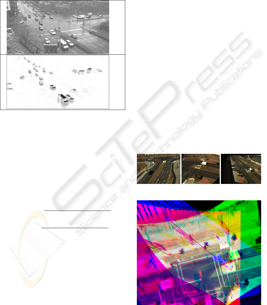
objects. The extracted objects (Figure 2) are then
grouped using a cluster analysis combined with
additional filters to avoid object splitting by
VISAPP 2008 - International Conference on Computer Vision Theory and Applications
586
infrastructure at intersections and roads. The
dedicated image coordinates as well as additional
parameters like area, volume, colour and
compactness can be computed for each extracted
traffic object. Further typical failures of such an
approach are e.g. ghosts and shadows.
(a)
(b)
Figure 2: (a) Grabbed Image (b) Extracted objects.
3.2 Coordinate Transformation and
Camera Calibration
The existing tracking concept is based on extracted
objects, which are geo-referenced to a world
coordinate system. This concept allows the
integration or fusion of additional data sources.
Therefore, a transformation between image and
world coordinates is necessary. Using collinearity
equations the world coordinates can be derived from
image coordinates:
()
()()
()()
()
()()
()( )
11 0 21 0 31
00
13 0 23 0 33
12 0 22 0 32
00
13 0 23 0 33
''
''
''
''
rxx ryy rc
XX ZZ
rxx ryy rc
rxx r yy rc
YY ZZ
rxx ryy rc
⋅− +⋅− −⋅
=+− ⋅
⋅− +⋅− −⋅
⋅− +⋅− −⋅
=+ − ⋅
⋅− +⋅− −⋅
(1)
X, Y world coordinates (to be calculated)
Z Z-component in world coordinates (to be
known)
X
0
, Y
0
, Z
0
position of the perspective centre in world
coordinates (exterior orientation)
r
11
, r
12
,…, r
33
elements of the rotation matrix (exterior
orientation)
x', y' uncorrected image coordinates (interior
orientation)
x
0
, y
0
coordinates of the principal point
c focal length (interior orientation)
The Z-component in world coordinates can be
deduced by appointing a dedicated ground plane.
Additional needed input parameters are the interior
and exterior orientation of the camera. The interior
orientation (principal point, focal length and
additional camera distortion) can be determined
using a well known lab test field. The 10 parameter
Brown camera model was used for describing
interior orientation (Brown, 1971). The parameters
can be determined by bundle block adjustment
(Remondino and Fraser, 2006).
Calculating the exterior orientation of a camera,
hence determining its location and orientation in a
well known world coordinate system is based on
previously measured ground control points (GCPs)
with differential GPS. The accuracy of the points is
in the range of less than 5 cm. With these
coordinates an approximate orientation can be
deduced using DLT (Luhman et al., 2006). For
improvement and elimination of erroneous GCPs the
exterior orientation is calculated eventually with the
spatial resection algorithm.
The scenario has been tested at the intersection
Rudower Chaussee / Wegedornstrasse, Berlin
(Germany) by observing with three cameras. The
observed area has an extent of about 100·100 m².
Figure 3 shows the original images taken from three
different positions and the derived orthophoto. The
good agreement between the three pictures is
obvious.
Figure 3a: Original images of the example scene.
Figure 3b: Orthophoto, generated from images of three
different observation positions.
MULTI-CAMERA DETECTION AND MULTI-TARGET TRACKING - Traffic Surveillance Applications
587
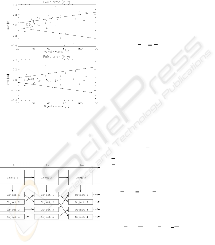
The following figure shows that the lateral error
of the GCPs in X- and Y-direction achieved by this
approach is 20 cm in 100m distance from the
projection centre.
Figure 4: Lateral error of GCPs in X- and Y-direction as a
function of the point distance from camera projection
centre.
3.3 Tracking, Trajectory Creation and
Fusion
In this paper object tracking is referred to
chronological object mapping (see figure 5).
Figure 5: Tracking principle.
A number of objects are recognized for each
image
k . For the n objects
i
k
R
a set of position data
for is available. The aim is to map the observation to
an existing object and to update its state values
describing this object, e.g. position or shape.
Tracking is done using a Kalman-filter
approach (Anderson and Moor, 1979) and
(Blackman, 1986). The basic idea consists of
transferring supplementary information concerning
the state into the filter approach in addition to the
measurement. This forecast of the measuring results
(prediction) is derived from earlier results of the
filter. The approach is recursive with that.
A map of the system state to the measurement
vector has to be done in order to describe a complex
state of an observed process:
kk
kk
ZHX
=
⋅+β+ε
(2)
Z
k
measurement of the sensor at time t
k
X
k
object state at t
k
β
k
unknown measurement offset
ε
k
random measurement error
H Observation matrix
H⋅ X
k
Measurement (object position)
The state-vector for each object consists of
position, speed and acceleration of the object in X-
axis and Y-axis direction. The measurement
statistics will be described by uncorrelated white
noise.
The movement model (state transition model,
plant model) is characterized by straight uniform
movement. Since this one is idealized performance,
the model has an additional error (predictions error,
plant noise).
(
)
k
k1 k
k
XtXU
+
=Φ Δ ⋅ +
(3)
Φ
calculated from the movement model
U
k
plant noise
If a (filtered) estimation is given at t
k
, then the
predicted state X’
k+1
at t
k+1
is:
()
kk1kk
k1 k
XtXttt
+
+
′
=
ΦΔ ⋅ = +Δ
(4)
The a posteriori state estimation is a linear
combination of the a priori estimation and the
weighted difference from the difference of forecast
and measurement:
k1 k1 k1 k1
XXK(ZHX)
+
+++
′′
=+ −
(5)
The initialization of the state-vector will be
done from two consecutive images. The association
of a measurement to an evaluated track is a
statistical based decision-making process. Errors are
related to clutter, object aggregation and splitting.
The decision criteria minimize the rejection
probability.
VISAPP 2008 - International Conference on Computer Vision Theory and Applications
588
If the object is leaving the observed area, the
trajectory will be finalized. The trajectory is also
finalized after a particular number of misses.
Figure 6: Example tracks.
The tracking process provides the possibility to
fuse data acquired from different sensors. The
algorithm is independent from the sensor as long as
the data are acquired based on a joint coordinate
system. Normally, this is achieved by transforming
the measured image coordinates into the object
coordinate system using calibration and exterior
orientation parameters (Spangenberg and Doering,
2006).
These trajectories are then used for different
applications e.g. for the derivation of traffic
parameters (TP).
4 RESULTS
Two examples were chosen to show the advantage
of the trajectory based object description.
4.1 Derivation of Traffic Parameters
In this approach, trajectories are used for
computation of traffic parameters (TP), by
associating the trajectory with a detector structure.
This structure can be a line or an area detector,
placed at distinctive places on roads or intersections.
Detectors may detect and store trajectory interaction.
The interaction for each trajectory with a detector
can be calculated by interpolations between pairs of
points. Furthermore, trajectories can be stored in a
source-destination (SD) matrix, giving advanced
information about directions of trajectories and
travel behaviour of the objects. All these data can be
aggregated over a predetermined interval.
On a traffic intersection in Nuernberg,
Germany, the described approach has been
implemented and tested. The coordinate
transformation, multi-object- tracking and trajectory
creation worked together on a designated PC.
Trajectories have been sent to a separate PC for the
analysis and computation of traffic parameters.
While this step is not complex, it has been done on a
remote computer, as this could be the expected
configuration for a real application.
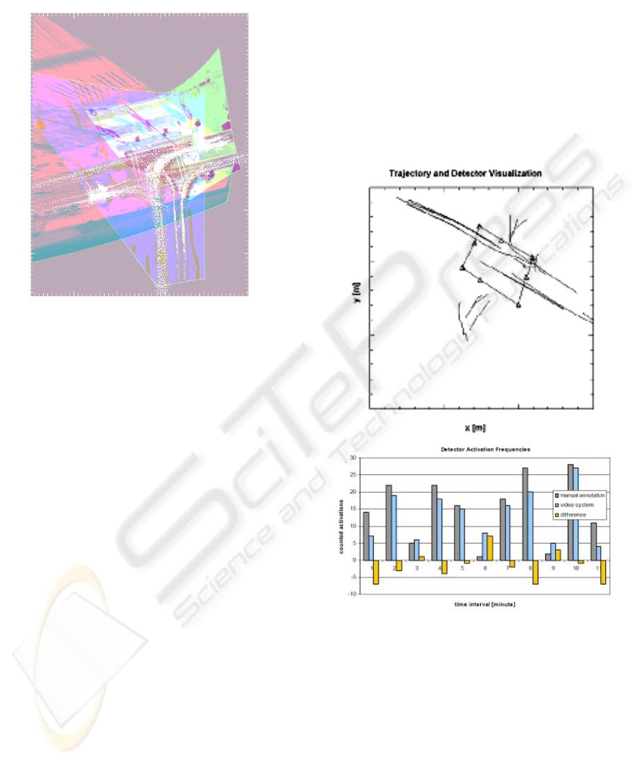
Figure 7: (top image) example trajectories in world
coordinate system, (bottom image) example count results
of one detector.
Incoming trajectories were evaluated and traffic
parameters computed. The results could be
visualized in real-time, showing the current situation
by means of the derived traffic parameters (Figure 7
top image). The update cycle for advanced
parameters was chosen as one minute. In each
interval, activation counts and new source
destination matrices have been filled and evaluated.
Long trajectories are necessary to make the approach
show its advantage. Detector activation and traffic
MULTI-CAMERA DETECTION AND MULTI-TARGET TRACKING - Traffic Surveillance Applications
589
objects counts, as well as integrated parameters for
the time cycles could be extracted very well (Figure
7 bottom image). However, source-destination
matrices would benefit highly and show more
significance, if the fragmentation of trajectories in
the scene could be reduced.
4.2 Analysis of Trajectories
A method for the deterministic description of
trajectories shall be introduced in the following. For
these trajectories this functional descriptions should
be as simple as possible. Linear movements can be
described by simple straights. But there are several
possibilities of description for curve tracks by
functional dependences.
It exist a variety of suggestions of possible
functions in the literature. Clothoid (Liscano and
Green, 1989) or G2-Splines (Forbes, 1989) are
curves whose bend depends of the arc length. An
alternative is the use of closed functions like B-
Splines, Cartesian polynomials fifth degree or
Polarsplines (Nelson, 1989).
(Anderson and Moor, 1979) have proposed a
description of tracks by hyperbolas. The great
advantage is that the derived parameters clarify
directly geometric connections and permit a
categorization of the trajectories.
Figure 8: Object trajectory, observed from three cameras
and a hyperbola fit to the trajectory
The hyperbola, shown in figure 8 was derived
by an estimation algorithm, which has also been
described e.g. by (Luhmann et al., 2006) and fits the
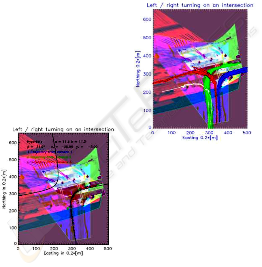
data well. Figure 9 shows an example of the
implemented approach. The coloured points and
crosses are related to the trajectory, observed from
different cameras. The hyperbola, also shown at
figure 9 can be used for an automatic classification
of right and left turns. In this case the angle φ is
positive or negative. With the calculated centre (x
m
,
y
m
) all four possibilities for right / left turning can be
classified.
Figure 9: Classified object trajectories.
5 CONCLUSION AND OUTLOOK
The presented approach for a traffic surveillance
system has been implemented and tested. Thus, it
could be shown that standard traffic parameters and
automatic scene description can be derived based on
video detection, tracking and trajectory analysis.
This is a necessary step for the future of traffic
surveillance systems. However, detection errors and
tracking problems can deteriorate the trajectory data.
This leads to less usable trajectories for analysis or
less reliable traffic parameters. Methods to detect
object detection errors and deteriorated trajectories
to stitch them together are key factors in the current
and future work.
VISAPP 2008 - International Conference on Computer Vision Theory and Applications
590

ACKNOWLEDGEMENTS
We would like to thank Ragna Hoffmann for the
support by the preparation of the paper and Marcel
Lemke for his support by acquiring the image data.
REFERENCES
Blackman, S.S. (1986). Multiple-Target Tracking with
Radar Applications, MA: Artech House, Dedham.
Brown, D.C. (1971). Close range camera calibration.
Photogrammetric Engineering, 37(8):855-866.
Collins, R., Amidi, O. and Kanade, T. (2002). An Active
Camera System for Acquiring Multi-View Video.
International Conference on Image Processing (ICIP),
Rochester, NY, (2002):131-140.
Datta, T.K., Schattler, K. and Datta, S. (2000). Red light
violations and crashes at urban intersections. Highway
and Traffic Safety: Engineering, Evaluation, and
Enforcement; Trucking and Motorcycles, (2000):52-
58.
Harlow, C. and Wang, Y. (2001). Automated accident
detection system. Highway Safety: Modeling,
Analysis, Management, Statistical Methods, and Crash
Location, (1746):90-93.
Kastrinaki, V., Zervakis, M., Kalaitzakis, K. (2003). A
survey of video processing techniques for traffic
applications. Image and Vision Computing, 21(4):359-
381.
Klein, L. A., Kelley, M. R., Mills, M. K. (1997).
Evaluation of overhead and in-ground vehicle detector
technologies for traffic flow measurement. Journal of
Testing and Evaluation, 25(2):205–214.
Kumar, P., Ranganath, S., Huang W.M., and Sengupta, K.
(2005). Framework for real-time behaviour
interpretation from traffic video. IEEE Transactions
on Intelligent Transportation Systems, 6(1):43-53.
Liscano, R. and Green, D. (1989). Design and
implementation of a trajectory generator for an indoor
mobile robot. Proceedings of the IEEE/RJS
International Conference on Intelligent Robots and
Systems. Tsukuba, Japan, (1989):380-385.
Luhmann, T., Robson, S., Kyle, S. and Harley, I. (2006).
Close-Range Photogrammetry. Whittles Publishing.
Luo, X.Z. and Bhandarkar, S.M. (2005). Real-time and
robust background updating for video surveillance and
monitoring. Image Analysis and Recognition,
3656:1226-1233.
Matsuyama, T. and Ukita, N. (2002). Real-time
multitarget tracking by a cooperative distributed vision
system. Proceedings of the IEEE, 90(7):1136-115.
Meagher, T., Maire, F. and Wong, O. (2004). A Robust
Multi-Camera Approach to Object Tracking and
Position Determination using a Self-Organising Map
Initialised through Cross-Ratio Generated “Virtual
Point”. CIMCA'04, Gold Coast, Australia.
Michalopoulus, P.G. (1991). Vehicle Detection Video
through Image-Processing – the Autoscope System.
IEEE Transactions on Vehicular Technology,
40(1):21-29.
Mittal, A. and Davis, L. (2001). Unified Multi-camera
Detection and Tracking Using Region-Matching.
viewed 20 August 2007,
<http://www.umiacs.umd.edu/~anurag/>.
Nelson, W.L. (1989). Continuous Steering-Function
Control of Robot Carts. IEEE Transactions on
Industrial Electronics,36(3):330–337.
Remondino, F. and Fraser, C. (2006). Digital Camera
Calibration Methods: Considerations and
Comparisons. ISPRS Commission V Symposium
'Image Engineering and Vision Metrology',
(2006):266-272.
Spangenberg, R. and Doering, T. (2006). Evaluation of
object tracking in traffic scenes. ISPRS, Commission V
Symposium, Image Engineering and Vision Metrology,
Dresden, Germany.
Setchell, C. and Dagless, E.L. (2001). Vision-based road-
traffic monitoring sensor. IEEE Proceedings-Vision
Image and Signal Processing, 148(1):78-84.
Wigan, M.R. (1992). Image-Processing Techniques
Applied to Road Problems. Journal of Transportation,
Engineering-Asce, 118(1):62-83.
Yung, N.H.C.and Lai, A.H.S. (2001). An effective video
analysis method for detecting red light runners. IEEE
Transactions on Vehicular Technology, 50(4):1074-
1084.
MULTI-CAMERA DETECTION AND MULTI-TARGET TRACKING - Traffic Surveillance Applications
591
