
HEAD POSE ESTIMATION IN FACE RECOGNITION ACROSS
POSE SCENARIOS
M. Saquib Sarfraz and Olaf Hellwich
Computer vision and Remote Sensing, Berlin university of Technology
Sekr. FR-3-1, Franklinstr. 28/29, D-10587, Berlin, Germany.
Keywords: Pose estimation, facial pose, face recognition, local energy models, shape description, local features, head
pose classification.
Abstract: We present a robust front-end pose classification/estimation procedure to be used in face recognition
scenarios. A novel discriminative feature description that encodes underlying shape well and is insensitive
to illumination and other common variations in facial appearance, such as skin colour etc., is proposed.
Using such features we generate a pose similarity feature space (PSFS) that turns the multi-class problem
into two-class by using inter-pose and intra-pose similarities. A new classification procedure is laid down
which models this feature space and copes well with discriminating between nearest poses. For a test image
it outputs a measure of confidence or so called posterior probability for all poses without explicitly
estimating underlying densities. The pose estimation system is evaluated using CMU Pose, Illumination and
Expression (PIE) database.
1 INTRODUCTION
Out of plane rotation of face has long been one of
the bottlenecks in the face recognition area. A face
recognition system should be able to handle
variations in face images due to pose, illumination
and other changes.
Recent research direction, in handling
variations due to pose, has been to first estimate the
pose of the test input face and then transform it to an
already learned reference pose (Lee and Kim, 2006).
Pose estimation/classification is thus a very useful
front-end processing tool for multi-view human face
analysis.
In 2D context, methods for face pose estimation
are either based on landmark feature detection (Zhao
and Gao,2006), appearance based subspace methods,
treating the whole face as one feature vector in some
feature subspace(Gong, 1996), or a combination of
both (Grundig and Hellwich, 2004). The former uses
certain localized landmarks points on the image and
tries to estimate the pose information by modelling
the displacement of these points across multiple
poses. This, however, is very sensitive to accurate
localization of landmarks and also assumes that the
ratios of these points do not change significantly
under different facial expressions. Sub-space
methods, on the other hand, although avoids these
problems of landmarks localization and modelling,
but it assumes that inter-pose variations are always
larger than intra-pose variations. This, generally, is
not true since different subjects across same pose
may have large appearance variations due to e.g.
glasses, expressions, illumination and skin colour.
In this paper, we propose a method which
overcomes these problems and is robust against the
aforementioned appearance variations across same
pose. We introduce a novel feature descriptor; Local
Energy based Shape Histogram (LESH), which is
based on local energy model of feature perception.
As stated in (kovesi, 2000), the local energy
response of an image is obtained by using Gabor
filtering, which gives relatively stable response in
terms of high energy on edges corners etc. On facial
images this will have high energy response along
landmark facial features such as eyes, nose and lips.
The proposed feature description models this
energy response in terms of local filter orientations
into a compact spatial histogram. These features
have good discriminative ability among large pose
variations. However, in order to discriminate
between adjacent poses and to cater in-pose
variations, due to other factors like glasses etc, we
235
Saquib Sarfraz M. and Hellwich O. (2008).
HEAD POSE ESTIMATION IN FACE RECOGNITION ACROSS POSE SCENARIOS.
In Proceedings of the Third International Conference on Computer Vision Theory and Applications, pages 235-242
DOI: 10.5220/0001087702350242
Copyright
c
SciTePress

need to learn these variations in a training phase. For
this, we propose an efficient learning procedure
which turns the multi-class problem into a two-class
one by modelling a pose similarity feature space
(PSFS) obtained from extra-pose (different pose)
and intra-pose (same pose) similarities in the
training phase. For a test image it outputs a measure
of confidence or probability for all poses without
explicitly estimating underlying densities. Our
system is evaluated on CMU-PIE face database (Sim
and Baker, 2002).
In section 2 we explain our approach for the
proposed feature extraction and description. Section
3 describes the pose estimation and classification
procedure in detail. With experimental results in
section 4, we conclude in section 5 with a brief
discussion.
2 FEATURE EXTRACTION
Multi-resolution Gabor based features are widely
used and proven very useful in face recognition.
Recently, (Baochang et all, 2007) has shown that
local Gabor phase patterns can provide a very
informative description and are quite useful in order
to model the orientation of the head (Bingpeng et
all, 2006). Another body of work exists which uses
this phase information to compute the local energy
content of the underlying signal, for detecting
interest points such as corners, edges, valleys
contours etc.
2.1 Local Energy Model
The local energy model developed by (Morrone and
Owens, 1987) postulates that features are perceived
at points in an image where the local frequency
components are maximally in phase.
Acos(φ (x)-φ(x))
nn
n
E(x) = max
A
φ(x) [0,2π]
n
n
∑
∈
∑
(1)
Where A
n
and φ
n
are the magnitude and phase of the
nth fourier component. This frequency information
must be obtained in a way such that underlying
phase information is preserved. For this linear phase
filters must be used in symmetric anti symmetric
pair. This is achieved by convolving the image with
a bank of Gabor wavelets kernels tuned to 5 spatial
frequencies and 8 orientations. At each image
location, for each scale and orientation, it produces a
complex value comprising the output of even
symmetric and odd symmetric filter, which gives the
associated magnitude and phase of that pixel.
G(e,o)=I(x,y)*ψ (z)
u,v n n u,v
(2)
Where ψ
u,v
is the bank of Gabor kernel and u,v is
the scale and orientation.
Originally (Robbins and Owen, 1997) has
proposed to use cosine of the deviation of each
phase component from the mean phase as a measure
of the symmetry of phase, however, this measure
results in poor localization and is sensitive to noise.
(Kovesi, 2000) extended this framework and
developed a modified measure, as given in equation
3, consisting of sine of the phase deviation,
including a proper weighing of the frequency spread
W and also a noise cancellation factor T.
(3)
W(x) A (x)(cos(φ (x) - φ(x)) - sin(φ (x) - φ(x)) ) - T
n
nn n
E=
A(x)+ε
n
n
∑
∑
⎢
⎥
⎣
⎦
The normalization by summation of all
component amplitudes makes it independent of the
overall magnitude of the signal, making it invariant
to illumination variations in images. For details of
this measure see (kovesi, 2000).
2.2 Proposed Feature Description
The local energy analysis in the preceding section is
intended to detect interest points in images with a
high reliability in presence of illumination and noise.
Hence, to detect these i2D structures (Kovesi, 2003)
proceeds by constructing principal moments of this
normalized energy measure, also termed as phase
congruency. In contrast to this, we rather use this
raw energy information and attempt to encode the
underlying shape. This is done in a way that makes it
invariant to scale variations but not to rotation since
rotation is precisely what we are trying to model.
2.2.1 LESH - Local Energy based Shape
Histogram
Motivated by the fact that this local orientation
energy response varies with respect to the
underlying shape, in our case the rotation of head
and since local energy signifies the underlying
corners, edges or contours, we generate a local
histogram accumulating the local energy along each
filter orientation on different sub-regions of the
VISAPP 2008 - International Conference on Computer Vision Theory and Applications
236
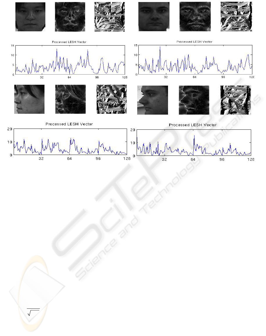
image. The local histograms are extracted from
different sub-regions of the image, and then
concatenated together, to keep the spatial
relationship between facial parts.
We proceed by obtaining an orientation label
map where each pixel is assigned the label of the
orientation at which it has
largest energy across all
scales.
The local histogram ‘h’ is extracted according
to the following:
h=w×E×δ(L - b)
r
r,b
∑
(4)
Where subscript ‘b’ represents the current bin,
‘L’ is the orientation label map, ‘E’ is the local
energy, as computed in equation 3, and ‘w’ is a
Gaussian weighing function centred at region ‘r’.
This weight is used to provide soft margins
across bins by small weighted overlap among
neighbouring sub-regions to overcome the problems
induced due to scale variations. In our experiments,
for a 32x32 region, σ is set to 20 in both directions.
As mentioned earlier, in order to keep the
spatial relation between facial parts, we extract 8
bins local histogram corresponding to 8 filter
orientations on 16 image partitions, which makes it a
128-dimentional feature vector.
Example feature extraction and associated
energy and orientation maps on two different
subjects in frontal and left profile pose, from CMU-
PIE database, are shown in Figure 1.
Figure 1 provides an intuitive look at the notion
of similarity across same pose among different
subjects, in terms of extracted local energy and
LESH features. This notional similarity is validated
empirically in section 3 by computing similarities
between extracted LESH features. Note how they
are quite invariant to person specific appearance
variations.
3 POSE ESTIMATION
The derived LESH features in the preceding section
provide a strong foundation on which to base our
pose estimation framework. These features are
robust against slight misalignment and scale
changes, but this comes with the cost of rather loose
description of facial landmark positions. Although
this does not affect while discriminating among
large pose variations such as the one shown in figure
xo yo
2πσ
222
1
[(x-r ) +(y-r ) ]/σ
w= e
r
(5)
Figure 1: Two different subjects at frontal and left profile pose. Their associated energy and orientation maps and extracte
d
LESH feature vectors.
HEAD POSE ESTIMATION IN FACE RECOGNITION ACROSS POSE SCENARIOS
237
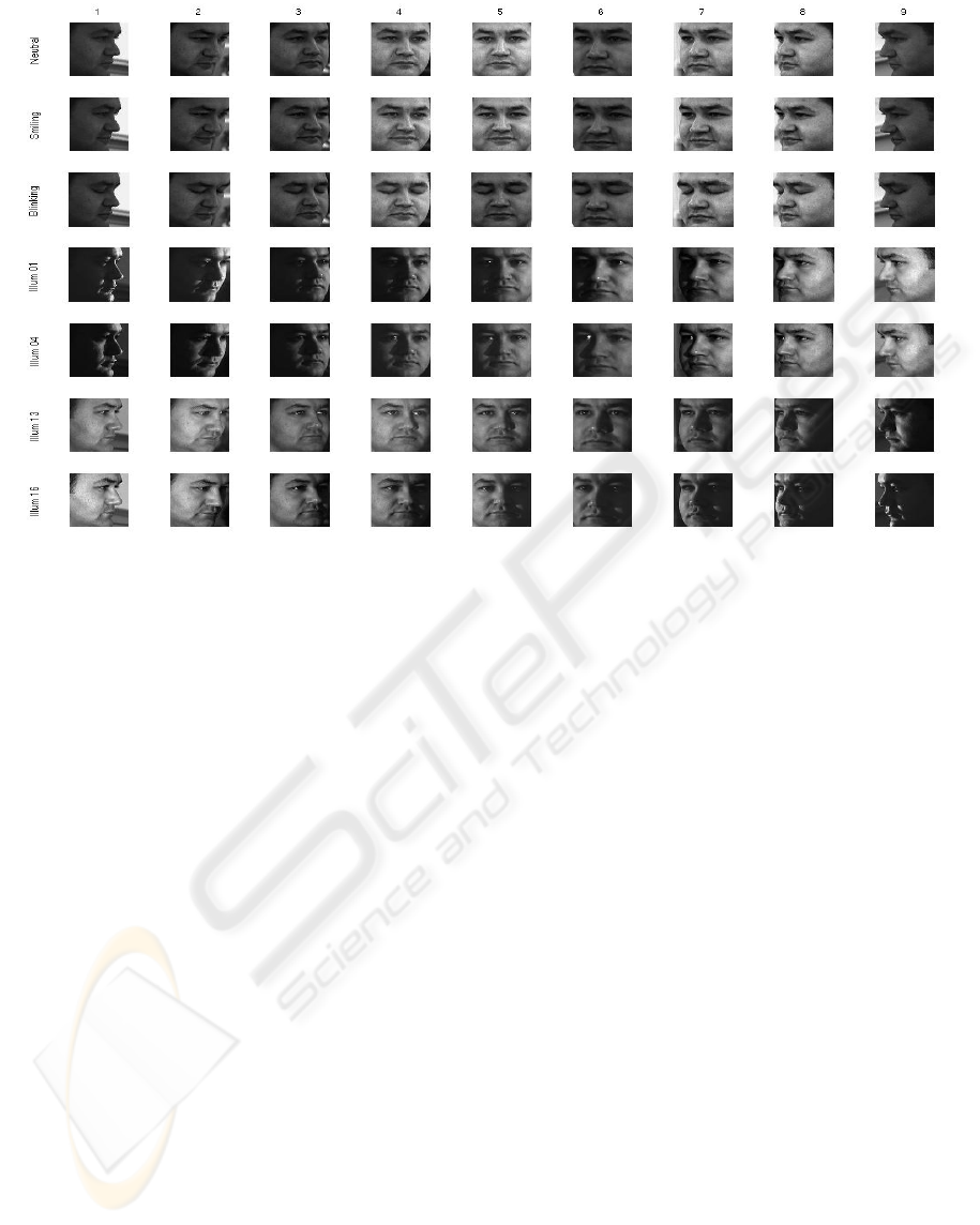
Figure 2: (along Rows) All 9 pose variations in CMU-PIE; pose 1(right profile) to pose 9 (left profile) views; (Along
columns) 7 imaging conditions; illumination and expression variations.
1, but discriminating among nearest pose changes,
by simply looking at similarity scores, is quite error
prone. Also, other variations, such as glasses,
expressions and to some extent illumination
(shadows), hinder a direct matching of these features
to decide on pose.
We therefore, learn these variations across
same pose from a training procedure in a novel way.
In particular, we lay down an effective classification
procedure that attempts to model these in pose
variations and performs quite well in discriminating
among slight pose variations.
Before explaining our pose estimation
framework, we introduce the facial database used in
our experiments.
3.1 PIE Database
We used a subset of PIE database to evaluate our
pose estimation algorithm. The portion of PIE
database, we used, consists of 21 illumination
differences of 68 subjects at 9 poses. Where 4
different illumination variations (out of 21) and 3
PIE expression variations per subject per pose are
considered, see figure 2 for an example.
Following the PIE naming convention
illumination variations correspond to flash 01, 04, 13
and 14, which captures well the extent of
illumination variations present, and expression
variations are neutral, smiling and blinking at frontal
lighting. 15 subjects are used for training and rest of
53 subjects for testing, amounting to 3339(7x53x9)
test examples.
In such scenarios one can expect that there will
be a huge overlap between nearest poses in the
derived feature space. We therefore introduce a new
classification framework which overcomes this and
models well the in-pose variations due to large
illumination and expression changes.
3.2 Proposed Approach
For the reasons stated earlier, we solve the pose
estimation as a classification problem from a
machine learning point of view. Instead of directly
modelling the extracted features and solve it as a
multiclass problem, we rather use similarity scores
of these features within same pose and among
different poses. This implies construction of a new
feature space based on these computed similarities.
Such an approach has huge benefit in that it
effectively turns a multiclass problem into a binary
two-class one while still representing well all the in-
pose variations. We model this new feature space.
VISAPP 2008 - International Conference on Computer Vision Theory and Applications
238

3.2.1 Pose Similarity Feature Space
We transform the whole problem into a new feature
space termed as pose similarity feature space
(PSFS). This PSFS is derived by computing
similarities between LESH features, coming from
same pose examples and similarities between
features from all the different pose examples.
As measure of similarity, we use modified K-L
divergence which is numerically stable, symmetric
and robust with respect to noise and size of
histogram bins. It actually gives a measure of
dissimilarity between two histograms. Thus low
values means more similar. It is defined as
hk
i,r i,r
d(H, K) = η (h log + k log )
r
i,r i,r
r
i
mm
i,r i,r
∑∑
(6)
Where, subscript ‘r’ runs over total number of
regions(partitions) and ‘i’ over number of bins in
each corresponding local histogram h and k, see
section 2.2.1, ‘m’ is the corresponding bin’s mean
and ‘η
r
’
is used as a provision to weigh each region
of the face while computing similarity scores. This
could be used, for instance, in overcoming the
problems due to expressions, by assigning a lower
weight to regions that are mostly affected. In our
experiments, for now, this η is set to 1.
For each example in our training set, we
compute these similarities with the rest of the
examples in the same pose on derived LESH
features. Concatenating them, give rise to an intra
pose ‘IP’ (same pose) similarity vector. Similarly
computing these similarities for each example with
all other examples in a different pose give rise to an
extra pose ‘EP’ similarity vector. Thus each example
is now represented in a PSFS as a function of its
similarities by these IP or EP vectors.
Note however, the dimensionality of this PSFS
is a direct function of the total number of examples
per pose in the training set. Therefore to put upper
limit on the dimensionality of this derived PSFS and
also to generate many representative IP and EP
vectors for a test face, as explained shortly, we
partition our training sets into some disjoint subsets
in such a way that each subset has same number of
subjects in each pose. To understand it better,
consider, for example, our training set comprising of
15 subjects, where each subject is in 7 different
illumination and expression imaging conditions in
each of the 9 poses, see figure 2. Therefore we have
15x7(105) examples per pose.
Deriving a PSFS directly means a 105
dimensional feature space, while partitioning it into
some disjoint subsets, such as each subset has all the
15 subjects but in some different combination of the
imaging condition, would yield a 15 dimensional
features space while still representing all the
variations we want to model.
3.2.2 Formal Description of our Approach
Formally, our approach is that we first partition the
training set into ‘k’ disjoint subsets (all N training
examples per pose per subset), the subsets are
disjoint in terms of the 7 imaging conditions (chosen
such as each subject is at a different imaging
condition in that subset).
In each subset, we then compute for each
example, its similarity to the rest of the examples in
the same pose on derived LESH features. Thus for
‘N’ examples per pose, we compute ‘N-1’
similarities for each example, concatenating them,
give rise to a ‘N-1’ dimensional intra-pose (IP)
similarity feature vector for each of the N examples.
Extra-pose (EP) vectors are obtained similarly by
computing these similarities between each example
in one pose with n-1 examples in a different pose by
leaving the same subject each time.
Thus we will have
IP samples and
EP samples for training. Where
‘N’ is number of examples/pose and ‘P’ is total
number of pose.
Although there will be a large number of EP
samples as compared to IP in the derived PSFS but
we note that, IP samples tend to have low values as
compared to EP and form a compact cluster in some
sub-space of the PSFS.
This is validated in Figure 3 which shows a 3-D
scatter plot of IP and EP samples from one of the
subset, by randomly choosing 3 features from IP and
EP similarity vectors. Note that IP samples are
depicted from all of the 9 poses while only those EP
samples are depicted which are computed among
large pose variations, such as between frontal and
left/right profile view or between left and right
profile view. The scatter plot is shown in logarithmic
scale for better viewing.
Figure 3 provides an intuitive look at how the
problem is easily separable when there are large
pose variations, while EP samples coming from
nearest pose examples can be seen as causing a
marginal overlap with the IP class.
The training set is used as a gallery and thus for
a test face, computing its similarity with all of the
examples in each pose in each subset of the gallery
produces many representative similarity vectors for
that test image. Therefore there is a good chance that
more of the similarity vectors, coming from where
the pose of the test face and gallery are same, falls in
HEAD POSE ESTIMATION IN FACE RECOGNITION ACROSS POSE SCENARIOS
239
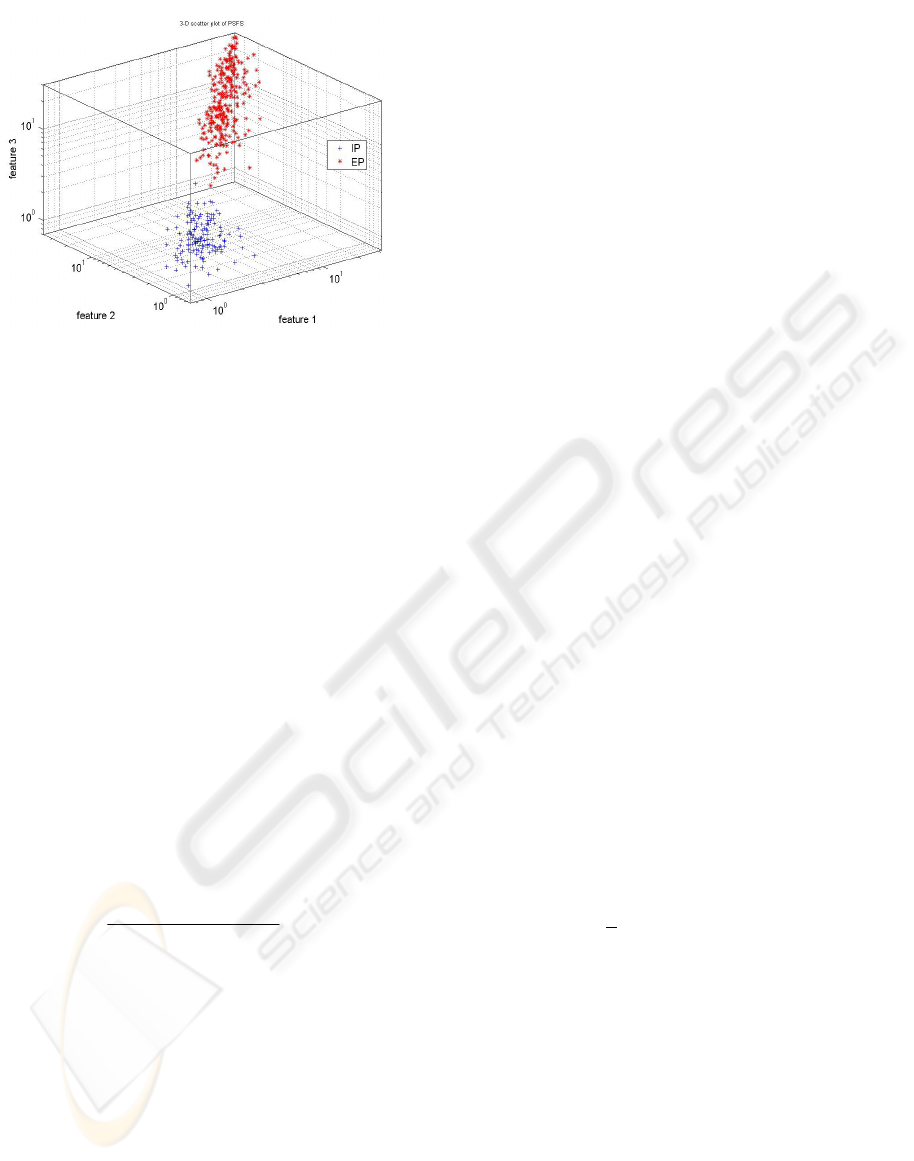
Figure 3: 3-D scatter plot of IP and EP vectors from one
of the subset. IP samples are drawn by randomly choosing
3 features from IP vectors from all of the 9 poses, while
EP samples are depicted only for large pose variations i.e.
b
etween frontal and left or right profile or between lef
t
and right profile view.
the IP class as compared to those which are coming
from even slight pose variations.
To learn the structure of this PSFS, we
therefore seek to separate the two classes. A simple
AdaBoost classifier (Schapire and Singer, 1999),
using nearest neighbour rule in each iteration, is
trained in this feature space for this purpose. That
provides a non-linear boundary between the two
classes.
For a test image, k vectors are obtained for each
pose by computing similarities from N-1 subjects in
each pose in each training subset. All of these are
classified to belong to either of the class. Final
decision is then made by considering only those
classified as IP, and assigning the label of the pose
from which majority of these are coming. This
probability for each pose is calculated simply by:
# of vectors in pose p
γ =
p
total # of vectors
((7)
As stated earlier, the rational of making subsets
of training set is now evident, as on one hand it
limits the dimensionality of the feature space, while
still representing well all the in-pose variations, and
on the other hand it generates many representative
vectors per pose for a test image, which provide us
with a probability score and helps in overcoming the
short comings of the classifier itself.
4 EXPERIMENTAL SETUP AND
RESULTS
Each 640x480 pixel PIE image is converted to
greyscale. A 128x128, closely cropped face part,
which is adjusted to remove any tilt bias by using
eye location is retained. We note that this is standard
procedure and any state of the
art face detector like
(Kanade et all, 1998) can be used for this purpose.
As described in the preceding section, for the
15 training subjects we have (105)15x7 examples
per pose. We partition them into 7 disjoint sets (each
with 15 examples) for each pose, as described
earlier.
This generates a 14 dimensional PSFS by
computing all the IP and EP vectors using LESH
features. AdaBoost is then trained on this PSFS.
For a test face, after extracting LESH feature,
we compute similarities with 14 examples in each
pose, for each training subset. This will generate one
14 dimensional similarity vector for each
representative pose in each subset; therefore, we will
have 7x1x9 (63) similarity vectors.
They are then classified as either IP or EP.
Those which are assigned label as IP are then further
used to compute probability scores, as described
earlier, for each of the 9 poses.
Final pose estimate is based on by assigning the
pose, which has highest score. This way we hope to
overcome the problem of any misclassified nearest
pose EP vectors.
Figure 4, on the next page, provides average
estimation results for each pose. While Table 1
summarizes the classification results obtained on all
the 371x9(3339) test examples in a confusion
matrix.
The overall average estimation accuracy is
84.06% in terms of rank-1 rates and 96.62% for
estimates within +
22.5
o
of accuracy.
VISAPP 2008 - International Conference on Computer Vision Theory and Applications
240
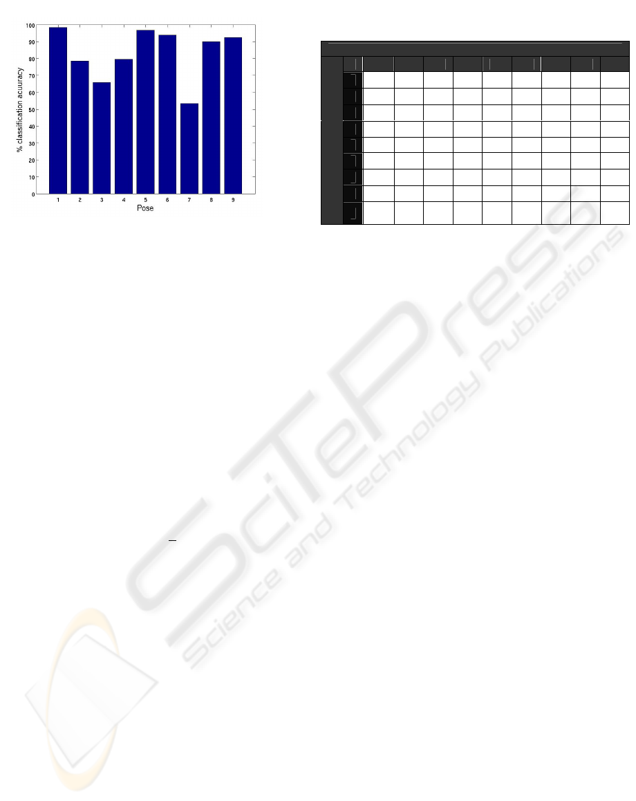
Figure 4: average classification scores for each pose.
In confusion matrix, the rows entries are indexed
by the true pose of the input images, while column
entries are labelled by our classification procedure-
determine pose. The entries on the diagonal indicate
the number of correctly classified images at each
pose. The sum of each row is 371 (an entry of 371
on the diagonal indicates perfect classification for
that pose).
5 CONCLUSIONS & DISCUSSION
We can compare our results with few of the recent
works (Yuan and casacent, 2005) and (Patnaik and
casasent, 2005) which use same database and
approximately the same setup, where former
achieved 82.4% rank-1 and later achieved 84.11%
rank-1 and 96.44% within +
22.5
o
,
they however,
pre- registered a test face to top 3 to 4 poses by
using 3 landmark locations on the face and did not
include expression variations.
Our system achieves best recognition scores on
full profile views, the reason, perhaps, stems from
the fact that a face at these views is most
distinguishable in terms of pure shape. Since our
system is build on a pure shape representation, these
results provides an intuitive relation if one looks at
the corresponding cropped faces at these poses,
figure 2.
The performance of our method on registering a
given face to the nearest pose (adjacent poses) is
above 96%. It provides us with probabilities for each
pose and that makes it very attractive from a
practical stand point, since this can be used directly
as our confidence in a given pose in the further face
recognition stage.
On concluding remarks, we have presented a
front-end pose estimation system which functions in
presence of illumination and expression changes. A
new feature description that encodes the underlying
shape well is proposed, and an efficient
classification procedure is suggested which turns the
multi-class problem into a binary one and solves the
problem of discriminating between nearest poses.
Based on this feature description, we
introduced to generate a generic similarity feature
space, that not only provides an effective way of
dimensionality reduction but also provides us with
many representative vectors for a given test feature
vector.
This is used in generating probability scores for
each pose without explicitly estimating the
underlying densities, which is very useful in later
face recognition across pose scenarios.
The system will be used for a subsequent
transformation of a test face to a reference pose for
face recognition.
We hope that the proposed feature description
and the notion of modelling the similarity space will
prove very useful in similar computer vision
problems.
ACKNOWLEDGEMENTS
The work is sponsored in part by the research grant
(#569400001; A/04/30771) from Higher Education
Commission, Pakistan and DAAD, Germany.
REFERENCES
Bingpeng M, Wenchao Z, Shiguang S, Xilin C, Wen G.,
2006 “Robust Head Pose Estimation Using
LGBP”,ICPR, vol.2, pp512-515.
Baochang Z., Shiguang S., Xilin C., and Wen G., 2007
“Histogram of Gabor Phase Patterns (HGPP):A Novel
Object Representation Approach for Face
Recognition”. IEEE Trans. on Image Processing,
vol.16, No.1, pp57-68.
Table 1: Confusion Matrix for all test examples.
System Pose Estimates
1 2 3 4 5 6 7 8 9
1
365 4 2 0 0 0 0 0 0
2
47 291 24 6 2 0 0 1 0
3
31 59 244 31 5 1 0 0 0
4
0 0 21 295 39 2 0 0 0
5
0 0 0 10 359 2 0 0 0
6
0 0 0 0 17 348 5 1 0
7
0 0 1 0 23 44 198 85 20
8
0 0 0 0 0 4 11 334 22
T
R
U
E
P
O
S
E
9
0 0 0 0 0 2 4 22 343
HEAD POSE ESTIMATION IN FACE RECOGNITION ACROSS POSE SCENARIOS
241

S. Gong, S. McKenna, and J. J. Collins. 1996 “An
investigation into face pose distributions”. In FG., pp
265.
Kovesi, P.D., 2000 “Phase congruency: A low-level image
invariant” Psychological Research,64, pp136-148.
Kovesi,PD,2003,”phase congruency detects corners and
edges”, in proc. Australian pattern recognition society
conference, pp 309-318.
Lee,H.S , Kim,D. 2006 “Generating frontal view face
image for pose invariant face recognition”, PR letters
vol.27, No. 7, pp 747-754.
Morrone, M.C., Owens, R.A., 1987 “Feature detection
from local energy”. PR Letters(6), pp 303-313.
R.Patnaik and D. P. Casasent, 2005 “MINACE-filter-
based facial pose estimation” in Biometric Technology
for Human Identification., Proc SPIE, pp 460-467.
H. A. Rowley, S. Baluja, and T.Kanade. 1998 “Neural
network-based face detection” IEEE PAMI, 20(1):23–
38.
Robbins, B., Owens, R. 1997 “2D feature detection via
local energy” Image and Vision Computing 15,pp353-
368.
R. Schapire and Y. Singer, 1999 “Improved boosting
algorithms using confidence-related predictions”.
Machine Learning, 37(3), pp.297-336.
T. Sim, S. Baker, and M. Bsat,2002 “The CMU Pose,
Illumination and Expression (PIE) database,” Proc.
Fifth IEEE FG, pp. 46-51.
Gründig M. and Hellwich,O., 2004, "3D Head Pose
Estimation with Symmetry Based Illumination Model
in Low Resolution Video", DAGM, LNCS, pp. 45-53.
C. Yuan and D. P. Casasent,2005 “Face recognition and
verification with pose and illumination variations and
imposer rejection,” in Biometric Technology for
Human Identification., Proc SPIE.
S. Zhao and Y. Gao, 2006 “Automated Face Pose
Estimation Using Elastic Energy Models”, The 18
th
ICPR, pp.618-621, Vol. 4.
VISAPP 2008 - International Conference on Computer Vision Theory and Applications
242
