
DISPLACEMENT PATCHES FOR GPU-ORIENTED
VIEW-DEPENDENT RENDERING
Yotam Livny, Gilad Bauman and Jihad El-Sana
Department of Computer Science, Ben-Gurion University of the Negev, Beer-Sheva, Israel
Keywords:
Level-of-detail, View-dependent rendering, Displacement mapping.
Abstract:
In this paper we present a new approach for interactive view-dependent rendering of large polygonal datasets,
which relies on advanced features of modern graphics hardware. Our preprocessing algorithm starts by gener-
ating a simplified representation of the input mesh. It then builds a multiresolution hierarchy for the simplified
model. For each face in the hierarchy, it generates and assigns a displacement map that resembles the original
surface represented by that face. At runtime, the multiresolution hierarchy is used to select a coarse view-
dependent level-of-detail representation, which is sent to the graphics hardware. The GPU then refines the
coarse representation by replacing each face with a planar patch, which is elevated according to the assigned
displacement map. Initial results show that our implementation achieves quality images at high rates.
1 INTRODUCTION
Polygonal meshes dominate the representations of 3D
graphics models due to their compactness and sim-
plicity. Recent advances in design, modeling, and ac-
quisition technologies have simplified the generation
of 3D models, which have led to the generation of
large 3D models. These models consist of millions
of polygons and often exceed the rendering capabili-
ties of advanced graphics hardware. Therefore, there
is a need to reduce the complexity of these models
to match the hardware’s rendering capability, while
maintaining their visual appearance. Numerous algo-
rithms have been developed to reduce the complex-
ity of graphics models. These include level-of-detail
rendering with multiresolution hierarchies, occlusion
culling, and image-based rendering.
View-dependent rendering approaches change the
mesh structure at each frame to adapt to the appro-
priate level of detail. Traditional view-dependent ren-
dering algorithms rely on the CPU to extract a level-
of-detail representation. However, within the dura-
tion of a single frame, the CPU often fails to extract
the frame’s geometry. In addition, communication be-
tween the CPU and the graphics hardware often forms
a severe transportation bottleneck. These limitations
usually result in unacceptably low frame rates.
Cluster-based multiresolution algorithms over-
come the CPU limitation by subdividing the dataset
into disjoint regions called clusters or patches, which
are simplified independently. These algorithms man-
age to reduce the time required to extract an adaptive
level of detail. However, the partition into patches of-
ten does not take into account fine object space error
and the generated clusters usually fail to reduce mem-
ory requirements.
In this paper, we present a novel cluster-based
multiresolution approach and an efficient view-
dependent rendering algorithm. In an off-line stage,
our algorithm simplifies the input model to reach a
coarse representation. It then constructs a multireso-
lution hierarchy for the simplified model. Each face
in the hierarchy includes a compact representation of
an original model’s patch.
The currently available graphics hardware pro-
vides advanced functionalities, such as a pro-
grammable pipeline and vertex texturing. These fea-
tures necessitate the development of new algorithms
and techniques to leveragethe introduced capabilities.
Our algorithm utilizes advanced graphics hard-
ware to efficiently represent patches as displacement
maps, which are generated by sampling the surface
of the original model. At runtime, the CPU extracts a
coarse view-dependent level-of-detail representation
from the multiresolution hierarchy and sends it to the
graphics hardware. Within the graphics hardware, the
GPU refines each face by replacing it with a cached
planar mesh, and elevating the inserted vertices using
the assigned displacement map.
181
Livny Y., Bauman G. and El-Sana J. (2008).
DISPLACEMENT PATCHES FOR GPU-ORIENTED VIEW-DEPENDENT RENDERING.
In Proceedings of the Third International Conference on Computer Graphics Theory and Applications, pages 181-190
DOI: 10.5220/0001095501810190
Copyright
c
SciTePress
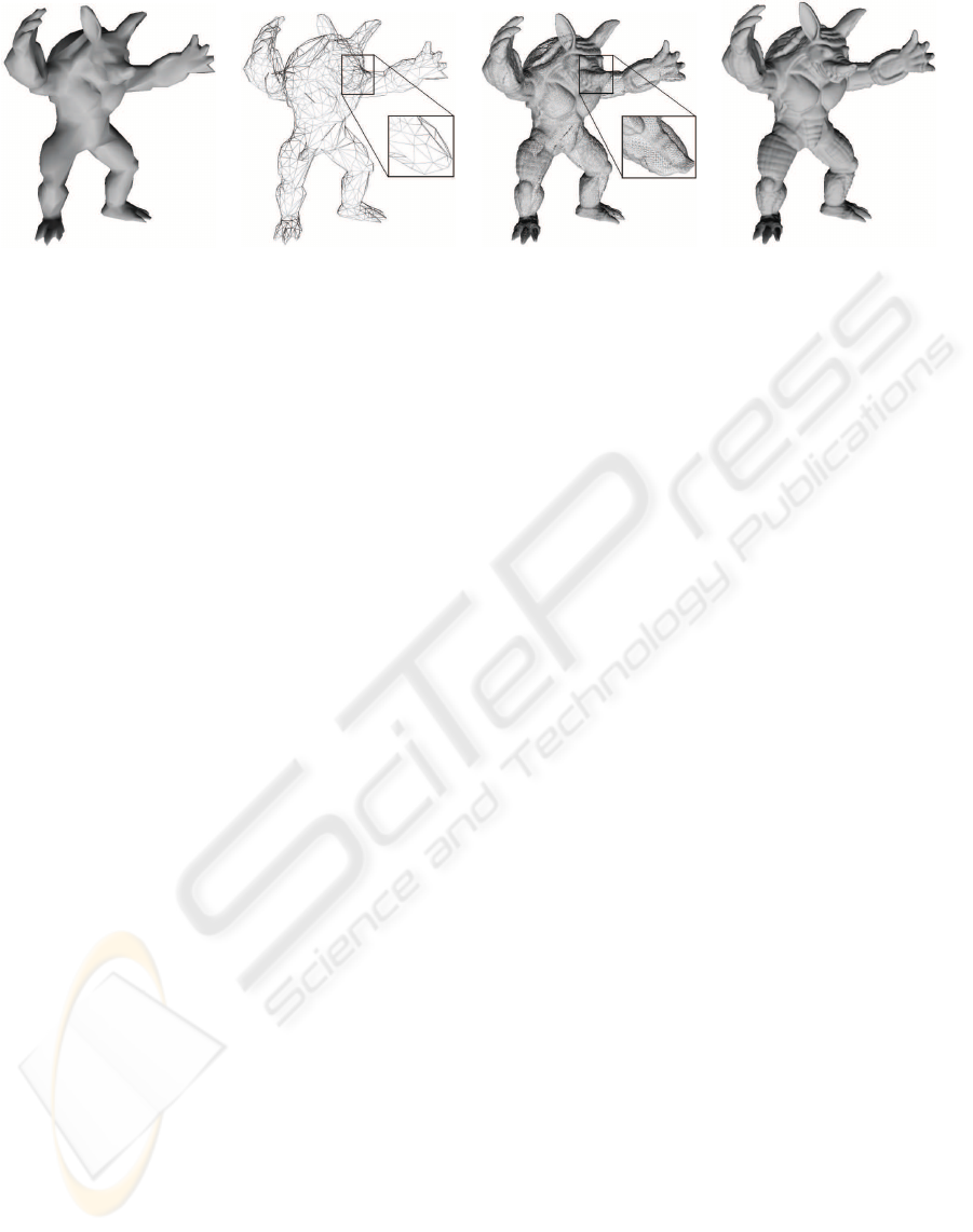
(a) (b) (c) (d)
Figure 1: The wireframe and shaded representation of a coarse front of the Armadillo model and the refined representation.
Our approach uses an error-guided subdivision to
partition the input model into disjoint patches, whose
geometry is compactly encoded using displacement
maps. Processing a coarse representation by the CPU
and applying mesh refinement using the GPU dynam-
ically balance the rendering load among the CPU and
the GPU, and dramatically reduce the communication
load between them. Our approach manages to seam-
lessly stitch adjacent patches without adding extra de-
pendencies or sliver polygons.
In the rest of this paper, we discuss closely related
work. Then we present our framework followed by
implementation details and results. Finally, we sum-
marize our work, present conclusions, and suggest po-
tential directions for future work.
2 RELATED WORK
In this section, we briefly discuss closely related re-
search.
View-dependent rendering schemes usually rely
on multiresolution hierarchies that encode various
levels of detail of the original model. Earlier ap-
proaches (Hoppe, 1997; Luebke and Erikson, 1997;
De Floriani et al., 1998; Pajarola, 2001) assume that
the multiresolution hierarchy fits entirely into local
memory and the extraction of adaptive levels of de-
tail is performed with the CPU.
Several approaches accelerated view-dependent
rendering by reducing dependencies limitation which
is used to validate the split and merge operations (Kim
and Lee, 2001), or integrating occlusion culling
within the view-dependent rendering frameworks (El-
Sana et al., 2001; Yoon et al., 2003). To handle large
datasets that do not fit in local memory, several ex-
ternal memory view-dependent rendering algorithms
were developed (El-Sana and Chiang, 2000; DeCoro
and Pajarola, 2002).
As the rendering capability of graphics hardware
improves and the size of datasets increase, the extrac-
tion of appropriate levelsof details within the duration
of a single frame becomes impractical for the CPU.
To overcome this limitation, cluster-based approaches
have been introduced (Erikson and Manocha, 2001;
Cignoni et al., 2004; Yoon et al., 2004).
The advances in graphics hardware have led to the
development of algorithms that inherently utilize the
introduced hardware capabilities. Several approaches
used the fragment processor to perform mesh sub-
divisions (Losasso et al., 2003; Bolz and Schr¨oder,
2005). The vertex processor was used to interpolate
different resolution meshes in a view-dependent man-
ner (Southern and Gain, 2003), deform displacement
maps (Schein et al., 2005), and map relief textures
onto polygonal models (Policarpo et al., 2005). Dis-
placement maps and the fragment processor were also
used to accelerate image-based rendering (Baboud
and D´ecoret, 2006; Kautz and Seidel, 2001).
Most GPU-based level-of-detail algorithms were
designed for height fields and terrain datasets (Livny
et al., 2007; Cignoni et al., 2003; Wagner, 2004;
Dachsbacher and Stamminger, 2004; Hwa et al.,
2005; Asirvatham and Hoppe, 2005; Schneider and
Westermann, 2006). Little work has been done to deal
with general 3D models. The programmable GPU
and displacement maps were used to approximate
general meshes (Doggett and Hirche, 2000; Guskov
et al., 2000) and for adaptive real-time rendering (Ji
et al., 2005; Donnelly, 2005; Hirche et al., 2004).
3 OUR APPROACH
In this section we present our framework for
interactive rendering of large polygonal datasets,
which leverages modern GPU capabilities, such as
programmability, vertex texturing, and geometry
caching. In a preprocessing stage, our algorithm sim-
plifies the input mesh, and then generates a multireso-
GRAPP 2008 - International Conference on Computer Graphics Theory and Applications
182
lution hierarchy for the simplified representation. For
each face f of the multiresolution, the algorithm con-
structs and assigns a displacement map that resembles
the original surface’s patch, corresponding to f. At
runtime, the hierarchy is used to select an appropri-
ate view-dependent level-of-detail representation (of
the simplified mesh), which we call the front mesh.
In each frame, the front mesh is sent to the graph-
ics hardware for rendering. Within the graphics hard-
ware, the GPU refines the front faces by replacing
each face with a cached triangular planar mesh, which
we call the generic tile. Finally, the vertices of the tri-
angular mesh are elevated according to the assigned
displacement map (See Figure 3).
3.1 Terminology
Let us define the normal n
i
at an internal point q
i
in
the triangle t as the interpolation of the three normals
at its vertices according to the distance of the normals
from q
i
. We shall refer to the normal n
i
as the inter-
polated normal.
Let M be a triangular mesh, and S be a simpli-
fied version of M. The vertex u
i
∈ S defines its cor-
responding point x
i
on M by shooting a ray from the
vertex u
i
, toward the mesh M, along the normal n
i
at
u
i
. An edge u
i
,u
j
is projected onto the shortest poly-
line on M connecting corresponding points x
i
and x
j
.
The trianglet
i
∈ S with vertices { u
i
,u
j
,u
k
} determines
a patch p
i
on M, which is defined by the three inter-
section points x
i
, x
j
, and x
k
. If the patches p
0
,··· , p
l
do not overlap, and every point in M is covered by ex-
actly one patch (except the boundary polylines), we
say that S corresponds to M, and the triangle t
i
∈ S
corresponds to the patch p
i
∈ M defined by t
i
.
A patch p
i
is denoted as an elevation of its corre-
sponding triangle t
i
if and only if a ray shot from any
point q
i
∈ t
i
along the normal at q
i
intersects the patch
p
i
at exactly one point (see Figure 2). A polygonal
mesh M is an elevation of another polygonal mesh
ˆ
M
if and only if
ˆ
M corresponds to M and every patch
p
i
∈ M is an elevation of its corresponding triangle
t
i
∈
ˆ
M. A simplification algorithm preserves elevation
if the input mesh is an elevation of every approxima-
tion generated by this algorithm (see Figure 2).
3.2 Model Simplification
Our framework requires the use of a simplification al-
gorithm that preserves elevation to generate an initial
approximation. This requirement is essential to define
a correspondence between the triangles of the simpli-
fied mesh and the patches of the original mesh, where
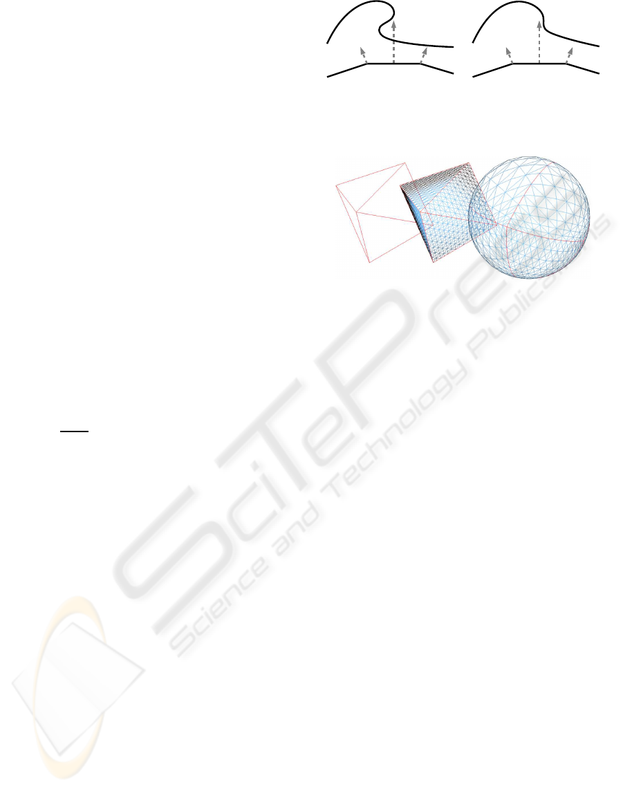
(a) (b)
Figure 2: The preserve elevation property (a) not preserving
elevation, and (b) preserving elevation.
Figure 3: An 8-face front for a sphere model, its generated
subdivision, and its refined representation.
every patch is an elevation of its corresponding trian-
gle (see Figure 3).
In typical view-dependent rendering, the selection
of the view-dependentlevel-of-detail representation is
performed using the CPU. However, the CPU often is
not capable of traversing and updating large adaptive
meshes within the duration of a single frame. For that
reason, we simplify the input model to reach an initial
representation and a small multiresolution hierarchy.
In order to generate an initial model, our algorithm
uses the half-edge simplification operator and the
quadric error metric (Garland and Heckbert, 1997).
However, by using both of these operators in conjunc-
tion, we risk obtaining a model that may not preserve
elevation. Therefore, during the simplification pro-
cess, we maintain a normal-cone for each vertex v,
which encodes the normals of its adjacent triangles
and those in its subtree. A half-edge collapse is de-
fined as valid if it does not result in a normal-cone
(for any affected vertex) that exceeds a half sphere.
The simplification algorithm executes only valid half-
edge collapses, one by one, which are ordered by their
quadric error value. The algorithm proceeds until it
reaches the target polygon count, or until no valid col-
lapses are left. The resulting mesh is used as the ini-
tial model for the construction of the multiresolution
hierarchy. To generate a multiresolution hierarchy for
the simplified mesh, one can use any of the previously
developed schemes (see Section 2).
Our approach requires preserving elevation prop-
erty among consecutive simplification steps, which
means that the mesh M
i
should be an elevation of the
mesh M
i−1
. In such a scheme, the elevation prop-
DISPLACEMENT PATCHES FOR GPU-ORIENTED VIEW-DEPENDENT RENDERING
183
erty may not be preserved with respect to the original
model, as this may prevent reaching necessary coarse
resolutions.
3.3 Generic Tile Structure
The generic tile is a triangle uniformly subdivided
into smaller triangles such that the number of vertices
along each one of its edges is the same. We shall refer
to the number of vertices along an edge of a generic
tile as the degree of the tile. A generic tile of degree k
includes (k− 1)
2
triangles and k(k− 1)/2 vertices.
The generic tile is used in two different steps of
our framework, the off-line preprocessing and the
real-time rendering (see Sections 3.4 and 3.6). These
two steps involve a geometric transformation, map-
ping the generic tile to match the scale and orientation
of the processed face.
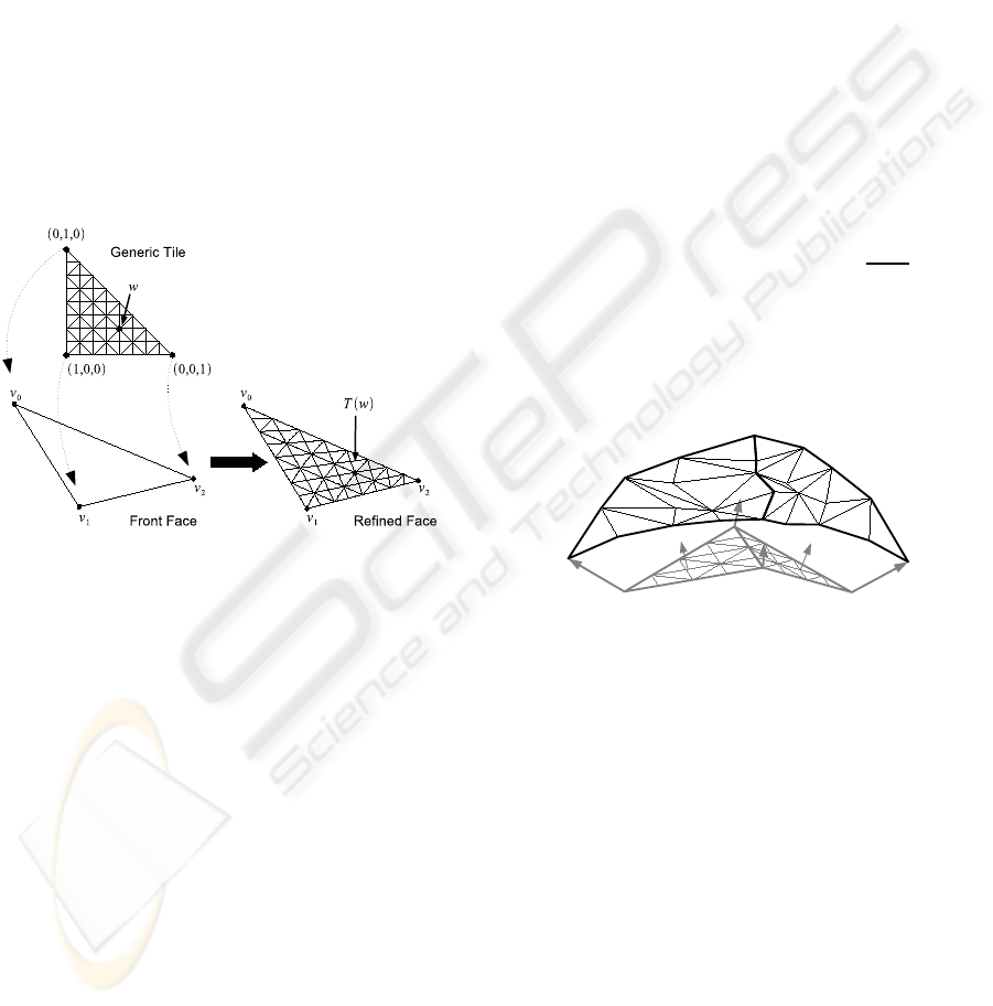
Figure 4: The mapping of a generic tile onto a front face
and the mapping of a tile vertex w to T (w) on the refined
front face.
We position the generic tile such that the three cor-
ner vertices of the generic tile are (1,0,0),(0, 1,0),
and (0,0, 1), and the coordinates of the remaining ver-
tices are determined accordingly.
The transformation T of the generic tile into an in-
put triangle t is performed by mapping the vertices
of the generic tile into the triangle t (refer to Fig-
ure 4). The position of each vertex in the mapped tile
is calculated using Equation 1a, where w
x
, w
y
, and
w
z
are the coordinates of the tile vertex w, and v
0
,
v
1
, and v
2
are the vertices of the triangle t. Note that
in such a scheme, the initial vertices of the generic
tile are mapped to the three vertices of the triangle
(T([0,1,0]) = v
0
, T([1,0,0]) = v
1
, and T([0,0,1]) =
v
2
). The normals at the mapped vertices are calcu-
lated in a similar manner using Equation 1b.
T (w) = w
x
∗ v
0
+ w
y
∗ v
1
+ w
z
∗ v
2
(1a)
N (w) = w
x
∗ n
0
+ w
y
∗ n
1
+ w
z
∗ n
2
(1b)
3.4 Displacement Maps
In the preprocessing stage, a displacement map is as-
signed to each face of the multiresolution hierarchy
to enable the recovery of the corresponding patch in
real-time rendering. The generation of these displace-
ment maps is performed using the generic tile.
For a generic tile of degree k, we define a dis-
placement map that includes k(k− 1)/2 values, as the
number of vertices in the generic tile. The generic tile
is then mapped onto the input face and an elevation
value is computed and assigned to each vertex v
i
of
the mapped tile. The elevation value for v
i
is deter-
mined by shooting a ray along the interpolated nor-
mal at v
i
, and computing the distance between v
i
and
the sample point x
i
on the patch. The sample point x
i
is determined based on the sampling method (refer to
section 3.5). In addition, we store the sampling error
ε for each face, and consider it later in the real-time
level-of-detail extraction.
Note that vertices along the edge e
k
= v
i
,v
j
are de-
termined by the two vertices v
i
and v
j
(refer to Equa-
tion 1a). As a result, refined vertices along common
edges have exactly the same position and the same
normal, which provide a common polyline for each
two adjacent patches (see Figure 5).
Figure 5: The refinement of the common edge of two adja-
cent faces results in exactly the same polyline.
3.5 Patch Sampling
Generating the displacement map for an input face is
practically the sampling of its corresponding patch.
According to Shannon’s theorem (Shannon, 1948),
for faithful sampling of an input function f, one needs
to sample with more than twice the frequency of
the highest-frequency component of f. In our ap-
proach, the sampling resolution is dictated by the de-
gree of the generic tile. Since our error-guided par-
tition scheme usually results in patches with low lo-
cal curvature, sampling artifacts are barely noticeable.
However, sometimes the constructed subdivision fails
to resemble the original surface and the naive sam-
pling does not provide quality images.
To overcome the above sampling limitation, we
consider the neighborhood of each sample when de-
GRAPP 2008 - International Conference on Computer Graphics Theory and Applications
184

termining its value. We have developed two sam-
pling algorithms – geometric simplification guided,
and interpolation-based – to determine the appropri-
ate value of a sample. The two approaches compute
the intersection of the rays with the patch, and de-
termine the neighborhood of a sample as the region
bounded by its eight adjacent rays.
The geometric simplification based approach sim-
plifies the neighborhood of an intersection point and
recomputes the intersection of the ray together with
the resulting surface. The second intersection is taken
as the sample’s value. The simplification is performed
only on the neighborhood while allowing limited sim-
plification on the boundary. To achieve faithful sim-
plification, we use the quadric error metric to order
the full edge collapses and determine the resulting
vertex position.
Our interpolation-based sampling algorithm inter-
polates the triangles within the neighborhood δ of the
sample point p. To compute such an interpolation,
one could bilinearly interpolate the centroids of the
triangles (c(t)) within δ weighted by w(t), which de-
pends on the size of the triangle t and its Euclidean
distance from p (see Equation 2).
The weight of a triangle is proportional to its
size, and inversely proportional to its distance from
p. However, it is not easy to distribute the triangle
weight into the two factors – triangle size, and its dis-
tance from p. For this reason, we uniformly subdivide
the neighborhood into almost equal cells in our cur-
rent implementation. The value of each cell is defined
as the average of the centroids of the triangles or frac-
tion of triangles that intersect the cell, weighted by
their size. Since the cells are almost the same size, we
only need to consider their distance from the sample
point p when interpolating the neighborhood of p.
p =
∑
t
i
∈δ(p)
c(t
i
)w(t
i
) (2)
3.6 Real-Time Rendering
In real-time, the CPU relies on the multiresolution hi-
erarchy to extract appropriate fronts, based on view-
parameters and illumination. The front should be de-
tailed enough to represent the visualized model with
respect to the view-parameters, but coarse enough to
be extracted within the duration of one frame.
In each frame, the adaptation process which runs
on the CPU, traverses the front nodes. For each active
node n, it determines whether n needs to be refined,
simplified, or remain in its current level. The updated
front is sent to the graphics hardware for rendering.
Within the graphics hardware, a single instance of
the generic tile is cached in video memory. In each
frame, the received front is refined by mapping the
generic tile into each face. Equation 1a and Equa-
tion 1b are used to determine the position of the re-
fined vertices and their interpolated normals, respec-
tively. For each vertex v
i
on the refined face, a dis-
placement value d
i
is fetched from the assigned dis-
placement map, and used to elevate v
i
along its nor-
mal. As a result, each face is replaced with (k − 1)
2
triangles, where k is the degree of the generic tile (re-
fer to Section 3.3). The total number of rendered tri-
angles is (k− 1)
2
times the number of triangles in the
front. In order to maintain interactivity, the total num-
ber of rendered triangles should not exceed the ren-
dering capabilities of the graphics hardware.
3.7 External Video Memory
The size of large polygonal datasets often exceeds the
capacity of main memory. Even though we assume
the simplified representation fits in main memory, the
displacement maps for large datasets may not fit in
video memory. Handling large datasets usually in-
cludes two uploading stages – from an external me-
dia into main memory and from main memory into
video memory. Uploading data from external media
into main memory has been widely studied (see Sec-
tion 2), and is beyond the scope of this paper.
The limited size of video memory in current hard-
ware calls for the design of schemes that load data
from main memory into video memory. Our External
Video Memory (EVM) manager uses a single texture
as a buffer, and manages data replacement effectively.
The EVM allocates a video buffer B which is im-
plemented as a texture that fits in video memory. Each
cached displacement map is stored as one row in the
video buffer. For every cached displacement map, the
EVM maintains an id, a priority, and an index. The
id is the displacement map identifier, priority mea-
sures the probability of reusing it, and index is a ref-
erence to the video buffer where the data is cached.
The EVM caches displacement maps required for the
next frame. In addition, it caches displacement maps
assigned to several tree levels above and below the
front level-of-detail, based on the available memory
space. The priority of a displacement map is deter-
mined by its distance from the front along the levels
of the hierarchy and its assigned error ε (refer to Sec-
tion 3.4). When it is needed to replace a displacement
map, the entry with the lowest priority is replaced by
the newly loaded displacement map.
DISPLACEMENT PATCHES FOR GPU-ORIENTED VIEW-DEPENDENT RENDERING
185
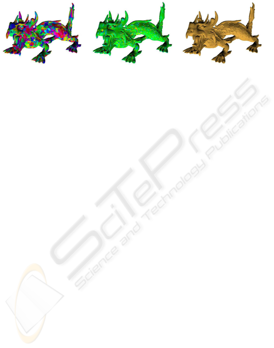
(a) (b) (c)
Figure 6: Asian Dragon Model: (a) the partition into patches (b) sampling error using interpolated base sampling, and (c) the
final image after GPU refinement.(green and red colors represent minimum and maximum error, respectively).
4 IMPLEMENTATION DETAILS
We have implemented our algorithm in C++ and Cg,
and adopted view-dependence trees (VDT) to main-
tain a multiresolution hierarchy with displacement
maps and support view-dependent rendering. We la-
bel this VDT with displacement maps as DM-VDT.
Quadric error metric (Garland and Heckbert, 1997) is
used to order the execution of the half-edge collapses.
A single generic tile, which is cached in video
memory as a Vertex Buffer Object (VBO), is repre-
sented by two arrays. One array encodes the vertices’
coordinates and the other encodes its triangle strip or-
der, for efficient rendering.
Since all displacement maps have the same size,
they can be easily stored in an array of displacement
maps, where each displacement map occupies a one-
dimensional array of elevation values. Such a scheme
avoids storing triangular maps in a rectangular texture
and, thus, simplifies memory management.
To maintain the original visual appearance, we en-
able the refinement process to recoverthe original sur-
face using approximately the same number of trian-
gles. It is important to note that the recovered surface
is a sampling of the original one, which may result in
small differences between them.
To achieve quality images, the screen-space error
must be determined for the selected front. Given a
screen-space error τ and a generic tile of degree k,
one can use kτ as the screen-space error to determine
the front. The refinement of this front would lead to
a final screen-space error τ. Unfortunately, in such a
scheme the actual screen-space error may exceed τ as
a result of an under-sampling error. To overcome this
limitation, we take into account the sampling error ε
at front extraction. The screen-space error of a face
f depends on its distance from viewpoint, its orienta-
tion, and its sampling error ε.
5 RESULTS
We have tested our implementation using various
datasets with different complexitiesand haveobtained
impressive results. In this section, we report samples
of these tests and their results which were obtained us-
ing a PC with 2.13 GHz Pentium Dual-Core, 2GB of
memory, and an NVIDIA GeForce 8800 GTX graph-
ics card with 768MB video memory.
5.1 Performance
Table 1 reports off-line construction time of view-
dependence trees. The first two columns present
the properties of the tested models. The VDT and
DM-VDT columns show the preprocessing time and
memory requirements of the classic view-dependence
trees (El-Sana and Varshney, 1999), and the proposed
approach. As can be seen, the total DM-VDT pre-
processing time is less than that of the classic VDT,
as a result of starting with a simplified representation.
In addition, the space complexity of our hierarchy is
less than 1/7 of that of the classic VDT, which results
from compactly representing the lower levels using
displacement maps (more in Section 5.2).
Table 2 summarizes real-time performance for
datasets that fit entirely in video memory. The first
two columns report the generic tile properties. The
last two columns show the performance, measured
in millions of triangles. These results were com-
puted by averaging the rendering of 1000 frames. The
peak performance of our graphics hardware is 280M
∆/sec when rendering cached VBO of indexed tri-
angle strips. The peak performance drops to 267M
∆/sec when fetching one elevation per vertex. As can
be seen, the transmission cost of a front is inversely
proportional to tile’s degree. In practice, our algo-
rithm is GPU-bound at tiles of degree k = 33. The
difference between the peak performance of 280M
∆/sec and the achieved performance of 267M ∆/sec
GRAPP 2008 - International Conference on Computer Graphics Theory and Applications
186
Table 1: Preprocessing time, memory requirement, and real-time performance.
Model VDT DM-VDT Face-Quality Runtime Runtime
Dataset Size Time Space Time Space
(min : sec) (MB) (min : sec) (MB) ME MSE ME MSE (f ps)
A. dragon 7.2M 63:29 327 49:09 49.7 0.44 0.010 0.67 0.12 130
T. statue 10.0M 81:23 461 68:10 63.6 0.38 0.033 1.52 0.45 89
Lucy 28.1M 217:45 1271 191:58 178.1 1.23 0.024 1.70 1.08 64
David 56.2M 420:09 2568 332:20 365.7 0.80 0.017 1.68 1.21 64
is a result of unavoidable CPU work and an additional
minor CPU-GPU communication load. Therefore,
tiles of higher degrees, such as k = 65, also receives
267M ∆/sec, and are useless because they reduce the
flexibility of the level-of-detail selection. Moreover,
tiles of degree k = 65 and higher, exceed the maximal
texture size supported in modern GPUs. According
to our results, the processing time of a frame is dis-
tributed as follows: 4% for level-of-detail selection,
24% for front transportation, and 72% for GPU-based
refinement.
Table 2: The performance with respect to tile degrees.
Tile Triangles VBO Vertex fetch
degree in a tile (∆/sec) (∆/sec)
9 64 154M 146M
17 256 216M 212M
33 1024 278M 264M
Our algorithm is designed to utilize the NVIDIA
GeForce 8 series. However, vertex texturing is al-
ready supported from the NVIDIA GeForce 6 series.
We have tested our implementation on a NVIDIA
GeForce 7800 GTX graphics card with 256MB video
memory, and compared it with a GeForce 8800 GTX.
We have found that the triangle throughput of the
GeForce 7 series is only 20% the throughput of the
GeForce 8 series. This is a direct result of the differ-
ences in the architecture of the GPUs. Our algorithm
relies heavily on vertex texturing, and therefore, its
performance is directly affected by the number of ver-
tex processors. The GeForce 7800 GTX (as well as
previous graphics cards) separates the vertex proces-
sors from the fragment processors. Because of this,
the GeForce 7800 GTX has only a few vertex proces-
sors, which limits the speed of vertex texturing. In
contrast, the GeForce 8800 GTX has a unified archi-
tecture in which the processors are general. Each pro-
cessor can be used as a vertex processor and therefore
accelerate the speed of vertex texturing. Since our
algorithm utilizes the vertex processors optimally, de-
spite the limitations of the GeForce 7800 GTX archi-
tecture, peak performance of the card is still achieved.
5.2 Image Quality
The quality of the resulting images is measured us-
ing two error metrics – sampling-quality and screen-
space errors. The sampling-quality error for a face f
is defined as the average distance between its refined
mesh and its corresponding patch. The screen-space
error is the screen projection of the average distance.
Table 1 reports the error and rendering time over
various datasets. The sampling-quality and screen-
error columns show maximal error (ME) and mean
square error (MSE). The last column reports the re-
sulting frame rates (fps) for a screen-space error τ ≤ 2
pixels. As can be seen, our algorithm achieves high
image quality at interactive rates. As a result of se-
lecting coarse fronts, our approach requires only 8%
extra triangles (after face refinement) in comparison
to classic VDT, to reach the same image quality. The
two last rows in Table 1 report the same performance
(fps) for the Lucy and the David models, as a result
of using the same screen space error τ in the tests,
thus rendering approximately the same number of tri-
angles for these two models. Using a uniform subdi-
vision for faces sometimes results in an overly large
number of triangles. This occurs when the patch rep-
resented by a face is close to planar. However, in or-
der to prevent such cases, our algorithm uses runtime
error control to adapt the selected level of detail to the
required quality. Therefore, when a face is close to
planar, our algorithm will select a more coarse repre-
sentation of the same area.
Figure 1 shows four images that illustrate the flow
of our approach. The two images in Figure 1(a) and
1(b) show the selected coarse front, and the images
in Figure 1(c) and 1(d) show the same front after be-
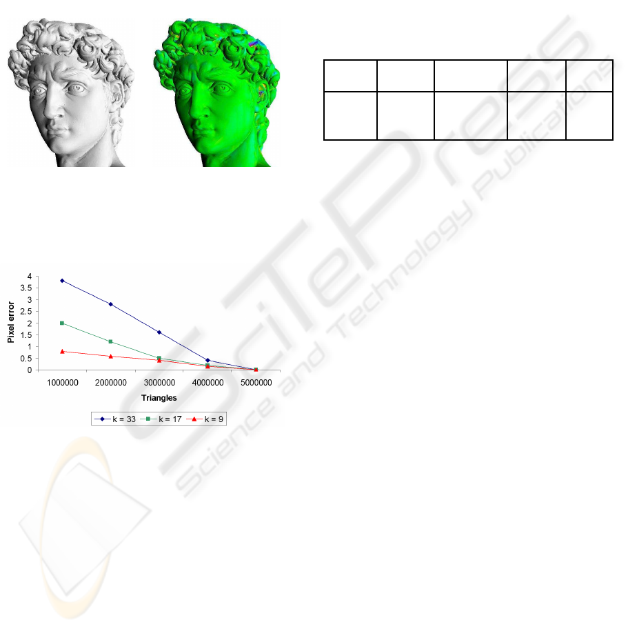
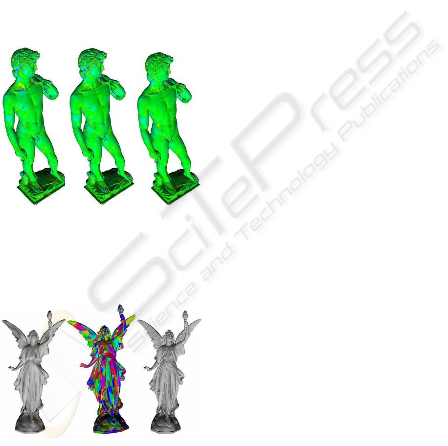
ing refined by the GPU. Figure 9 shows a color cod-
ing of the accuracy of the three sampling algorithms –
naive, simplification guided, and interpolation-based
(see Section 3.5) – using the David model. As can be
seen, the interpolation-based approach provides the
best results, and the naive approach provides the least
accurate sampling. Figure 10 illustrates the flow and
performance of our approach using the Lucy model.
The models Figure 9 and Figure 10 were rendered
DISPLACEMENT PATCHES FOR GPU-ORIENTED VIEW-DEPENDENT RENDERING
187
at approximately 64 fps with pixel error less than 2.
Figure 7 shows a close-up view of the David model.
In order to emphasize potential screen-space error,
we used a large error, τ = 15. Figure 6 shows the
coarse front (which is the same as mesh partition
into patches), the sampling error, and the final image
(after GPU refinement) of the Asian Dragon model
(7.2M f aces). Figure 8 presents the tradeoff between
the degree of the generic tile and the visual quality (as
pixel error), as was measured on the Lucy model.
(a) (b)
Figure 7: A closeup of the David Model: (a) A shaded view
of the model, (b) The screen-space errors (green and red col-
ors represent minimum and maximum error, respectively).
Figure 8: The screen-space error for Lucy, according to the
number of triangles for different tile degrees k.
5.3 External Video Memory
Table 3 presents the performance of our external
video memory scheme with respect to different tile
degrees. The third column reports the number of dis-
placement maps that fit into a 16MB EVM buffer (a
single texture). The face binding column shows the
number of displacement maps we were able to up-
load into the video memory within a second, while
EVM is disabled. Without EVM, it was not possi-
ble to achieve interactive rates for a front that con-
tained more than 100 faces. The EVM column reports
the number of displacement maps uploaded into the
video memory within a second, when EVM was en-
abled. It is apparent that the EVM manager improves
caching speed by a factor 30. In addition, the EVM
manager enables temporal coherence among consecu-
tive frames – our results show that at least 94% of the
displacement maps required for the next frame, are al-
ready cached in the video buffer. When comparing the
caching efficiency of different tile degrees (referring
to the number of cached elevation values per second),
we conclude that the larger the generic tile, the better
the utilization of the communication channel.
Table 3: The performance of EVM manager.
Tile Faces Entries Face EVM
degree in a tile in a buffer binding
9 64 373K 3.5K 147K
17 256 94K 2.7K 78K
33 1024 29K 2.5K 30K
5.4 Comparison with Other Algorithms
Next, we compare our approach with some of the
previously developed level-of-detail rendering ap-
proaches based on their published results.
The HLOD (Erikson and Manocha, 2001), the
Tetrapuzzles (Cignoni et al., 2004), and the Quick-
VDR (Yoon et al., 2004) algorithms present a level-
of-detail rendering algorithm that uniformly subdi-
vide an input 3D model into disjoint patches, which
are simplified, ordered in triangle strip formats and
stored in a VBO. These algorithms explicitly store the
geometry of the input model in a hierarchy, and uti-
lize only limited geometry transfer formats (several
non-optimized triangle strips for a single patch). In
contrast, our approach represents patches as displace-
ment maps. Using displacement maps for implicit
representation of a model saves approximately 85%
of the application’s memory. Moreover, the generic
tile is cached in an optimized triangle strip, which
implies a single transportation and rendering pass for
each face. We compare our algorithm to those algo-
rithms using models that fit entirely into main mem-
ory. In such a scenario, these algorithms are GPU-
bound and render approximately 280M∆/sec, using
our PC. As a result of using an error guided subdi-
vision scheme, our algorithm is able to utilize CPU-
based patch culling during runtime. Using CPU-
based culling for patches in GPU-bounded algorithms
increases the performance beyond the maximum ren-
dering capability of the GPU. Our algorithm increases
the performance by 35%, and renders approximately
356M∆/sec. In addition, our algorithm requires only
87% of the triangles required by the above mentioned
GRAPP 2008 - International Conference on Computer Graphics Theory and Applications
188
approaches, to reach a two-pixel error image quality.
This also means that the rendering performance of our
algorithm is faster by 16%.
Ji et al. (Ji et al., 2005) suggested a GPU-based
view-dependent rendering that selects and renders a
level-of-detail within the GPU. Instead of fully imple-
menting their approach using the GPU, they emulated
a GPU using a CPU-based implementation, as a result
of the complexity of their algorithm. The simplicity
of our approach leads to a straightforward implemen-
tation (using several Cg instructions) that efficiently
utilizes the processing power of the GPU.
(a) (b) (c)
Figure 9: The accuracy of (a) naive (b) geometric simpli-
fication guided, and (c) interpolated-based sampling, using
the David model(green and red colors represent minimum
and maximum error, respectively).
(a) (b) (c)
Figure 10: The Lucy Model: (b) An 8K faces coarse front,
(b) The mesh partition imposed by the coarse front, and (c)
The refined mesh using generic tile of degree 33.
6 CONCLUSIONS AND FUTURE
WORK
We have presented a framework for a GPU-based
view-dependent rendering of general 3D polygonal
datasets. The simplified representation is an error-
guided subdivision of the input model into disjoint
patches. The geometry of these patches is encoded
into displacement maps. Processing smaller multires-
olution hierarchies within the CPU removes the bot-
tleneck, and makes the CPU available for other gen-
eral purpose computations. In addition, the transmis-
sion of a coarse level-of-detail along with displace-
ment maps reduces the communication load between
the CPU and the GPU. This is a result of utilizing
video memory for caching and transmitting only un-
cached primitives. In summary, our approach man-
ages to seamlessly stitch adjacent patches without
adding extra dependencies or sliver polygons.
We observe several possibilities for future en-
hancements to our algorithm and for further research.
One might wish to eliminate the case of overly large
triangulations of planar patches. It would be interest-
ing to implement a GPU-based adaptive subdivision,
instead of a uniform patch subdivision. Furthermore,
for another boost in performance, the integration of
existing occlusion culling techniques into our algo-
rithm may be considered.
ACKNOWLEDGEMENTS
This work is supported by the Lynn and William
Frankel Center for Computer Sciences and the Tuman
Fund. In addition, we would like to thank the review-
ers for their constructive comments.
REFERENCES
Asirvatham, A. and Hoppe, H. (2005). GPU Gems 2,
chapter Terrain rendering using GPU-based geome-
try clipmaps., pages 27–45. Addison-Wesley Profes-
sional.
Baboud, L. and D´ecoret, X. (2006). Rendering geometry
with relief textures. In Proceedings of Graphics Inter-
face ’06, pages 195–201.
Bolz, J. and Schr¨oder, P. (2005). Evaluation of subdivision
surfaces on programmable graphics hardware. Sub-
mitted.
Cignoni, P., Ganovelli, F., Gobbetti, E., Marton, F., Pon-
chio, F., and Scopigno, R. (2003). P-BDAM – planet-
sized batched dynamic adaptive meshes. In Proceed-
ings of Visualization ’03, pages 147–155.
DISPLACEMENT PATCHES FOR GPU-ORIENTED VIEW-DEPENDENT RENDERING
189

Cignoni, P., Ganovelli, F., Gobbetti, E., Marton, F., Pon-
chio, F., and Scopigno, R. (2004). Adaptive TetraPuz-
zles – efficient out-of-core construction and visualiza-
tion of gigantic polygonal models. ACM Transactions
on Graphics, 23(3):796–803.
Dachsbacher, C. and Stamminger, M. (2004). Rendering
procedural terrain by geometry image warping. In
Proceedings of Eurographics/ACM SIGGRAPH Sym-
posium in Geometry Processing, pages 138–145.
De Floriani, L., Magillo, P., and Puppo, E. (1998). Efficient
implementation of multi-triangulations. In Proceed-
ings of Visualization ’98, pages 43–50.
DeCoro, C. and Pajarola, R. (2002). Xfastmesh: Fast view-
dependent meshing from external memory. In Pro-
ceedings of Visualization ’02, pages 363–370.
Doggett, M. and Hirche, J. (2000). Adaptive view de-
pendent tessellation of displacement maps. In Pro-
ceedings of the ACM SIGGRAPH/EUROGRAPHICS
workshop on Graphics hardware ’00, pages 59–66.
Donnelly, W. (2005). GPU Gems 2, chapter Per-Pixel Dis-
placement Mapping with Distance Functions, pages
123–136. Addison-Wesley Professional.
El-Sana, J. and Chiang, Y. (2000). External memory view-
dependent simplification. Computer Graphics Forum,
19(3):139–150.
El-Sana, J., Sokolovsky, N., and Silva, C. (2001). Integerat-
ing occlusion culling with view-dependent rendering.
In Proceedings of Visualization ’01, pages 371–378.
El-Sana, J. and Varshney, A. (1999). Generalized view-
dependent simplification. Computer Graphics Forum,
18(3):C83–C94.
Erikson, C. and Manocha, D. (2001). Hierarchical levels
of detail for fast display of large static and dynamic
environments. In Proceedings of symposium on Inter-
active 3D graphics ’01, pages 111–120.
Garland, M. and Heckbert, P. (1997). Surface simplifica-
tion using quadric error metrics. In Proceedings of
SIGGRAPH ’97, pages 209–216.
Guskov, I., Vidimˇce, K., Sweldens, W., and Schr¨oder, P.
(2000). Normal meshes. In Proceedings of the 27th
annual conference on Computer graphics andinterac-
tive techniques ’00, pages 95–102.
Hirche, J., Ehlert, A., Guthe, S., and Doggett, M. (2004).
Hardware accelerated per-pixel displacement map-
ping. In Proceedings of Graphics Interface ’04, pages
153–158.
Hoppe, H. (1997). View-dependent refinement of progres-
sive meshes. In Proceedings of SIGGRAPH ’97, pages
189–198.
Hwa, L., Duchaineau, M., and Joy, K. (2005). Real-time op-
timal adaptation for planetary geometry and texture:
4-8 tile hierarchies. IEEE Transactions on Visualiza-
tion and Computer Graphics, 11(4):355–368.
Ji, J., Wu, E., Li, S., and Liu, X. (2005). Dynamic lod on
gpu. In Computer Graphics International ’05, pages
108–114.
Kautz, J. and Seidel, H. (2001). Hardware accelerated dis-
placement mapping for image based rendering. In
Proceedings of Graphics Interface ’01, pages 61–70.
Kim, J. and Lee, S. (2001). Truly selective refinement of
progressive meshes. In Proceedings of Graphics In-
terface ’01, pages 101–110.
Livny, Y., Sokolovsky, N., Grinshpoun, T., and El-Sana, J.
(2007). A gpu persistent grid mapping for terrain ren-
dering. The Visual Computer. to appear.
Losasso, F., Hoppe, H., Schaefer, S., and Warren, J. (2003).
Smooth geometry images. In Proceedings of Euro-
graphics/ACM SIGGRAPH Symposium in Geometry
Processing, pages 138–145.
Luebke, D. and Erikson, C. (1997). View-dependent simpli-
fication of arbitrary polygonal environments. In Pro-
ceedings of SIGGRAPH ’97, pages 199–207.
Pajarola, R. (2001). Fastmesh: efficient view-dependent
meshing. In Proceedings of Pacific Graphics ’01,
pages 22–30.
Policarpo, F., Oliveira, M., and Comba, J. (2005). Real-
time relief mapping on arbitrary polygonal surfaces.
In Proceedings of the 2005 symposium on Interactive
3D graphics and games ’05, pages 155–162.
Schein, S., Karpen, E., and Elber, G. (2005). Real-
time geometric deformation displacement maps us-
ing programmable hardware. The Visual Computer,
21(8):791–800.
Schneider, J. and Westermann, R. (2006). GPU-friendly
high-quality terrain rendering. Journal of WSCG,
14(1-3):49–56.
Shannon, C. E. (1948). A mathematical theory of commu-
nication. Bell System Technical Journal, 27:379–423,
623–656.
Southern, R. and Gain, J. (2003). Creation and con-
trol of real-time continuous level of detail on pro-
grammable graphics hardware. Computer Graphics
Forum, 22(1):35–48.
Wagner, D. (2004). Terrain geomorphing in the vertex
shader. ShaderX2: Shader Programming Tips &
Tricks with DirectX 9.
Yoon, S., Salomon, B., and Manocha, D. (2003). Interac-
tive view-dependent rendering with conservative oc-
clusion culling in complex environments. In Proceed-
ings of Visualization ’03.
Yoon, S. E., Salomon, B., Gayle, R., and Manocha, D.
(2004). Quick-vdr: Interactive view-dependent ren-
dering of massive models. In Proceedings of Visual-
ization ’04, pages 131–138.
GRAPP 2008 - International Conference on Computer Graphics Theory and Applications
190
