
REALISTIC
RAIN RENDERING
Yoshiki Mizukami, Katsuhiro Sasaki and Katsumi Tadamura
Graduate School of Science and Engineering, Yamaguchi University, 2-16-1 Tokiwa-Dai, Ube 755-8611, Japan
Keywords:
Animation, Rendering natural phenomena, Particle systems.
Abstract:
We propose a method for rendering realistic three-dimensional raining scene. The proposed method gives
two main contributions to rendering raining scene. The first one is to propose a simple model that deals with
temporal-spatial localities such as wind effect, density and intensity of rainfall, and raindrop brightness, so
as to represent environmental conditions that differs on a scene-to-scene basis. The other one is to propose
a raindrop trajectory computing method whose computation load immunes to the number of raindrop, wind
effect and complicated camera movement. Due to the above-mentioned contributions, the proposed method
can represent essential aspects in raining scene, such as spatial changes of rain in urban canyon or temporal
changes due to the moving wisp of rain.
1 INTRODUCTION
Although various factors are concerned with the re-
ality of landscape rendered with Computer Graph-
ics (CG), the representation about weather or mete-
orological condition is one of the essential factors.
This paper proposes a method for realistically render-
ing raining scenes, which can represent the temporal-
spatial localities such as wind effect, density and in-
tensity of rainfall, and raindrop brightness.
For the clarification of background, the previous
studies related to rainfall is summarized below, es-
pecially focusing on the relationship with our study.
Kaneda et al. proposed a representation method of
water droplet on the windshield for driving simulator
(Kaneda et al., 1999). Sato et al. proposed a faster
method by using the capability of graphics hardware
(Sato et al., 2002). Many researchers have studied
rendering methods of the trajectory of raindrops. In
early CG animation, the falling motion of translucent
white spheres was synthesized into the background
scene on the basis of the particle system (Reeves,
1983; Sims, 1990). Starik et al. proposed a tech-
nique for combining raindrop trajectory with video
images, where rain intensity and raindrop size can be
adjusted by controlling parameters (Starik and Wer-
man, 2003). Feng et al. proposed a fast GPU-based
method of rendering the trajectory of windblown rain-
drops and raindrop splashes (Feng et al., 2005a; Feng
et al., 2005b). Garg and Nayar proposed a method
for improving appearance of rain trajectory that uti-
lizes a database of rain streaks under various illumina-
tion conditions (Garg and Nayar, 2006). Several other
studies have been done for creating real-time rain an-
imation taking into account environmental light con-
dition. For example, handwritten rain strokes were
colored based on the environmental light condition
(Wang et al., 2006). Multiple layers of rain tex-
ture were used particularly for expressing rain drop
motion parallax (Tatarchuk, 2006). A texture dis-
torted according to optical properties of raindrops was
mapped onto a raindrop (Rousseau et al., 2006).
These previous contributions are very useful for
rendering raining scenes with feasible computation
requirements. Now it should be noted that parti-
cle system was employed in all study except Starik’s
method. These particle-based methods generated
raindrops randomly and uniformly. In addition, the
raindrop movement was not influenced by the wind.
Even so, these wind conditions were uniform. How-
ever it is clear that the density and the falling trajec-
tory of real-life raindrops reflect the temporal-spatial
changes of the wind conditions. These characteristic
localities in raining scene are considered as essential
factors for providing raining reality, and the problem
about these factors in the previous studies should be
improved for more broad applications. In addition,
apparent movements of raindrops caused by the cam-
era movement were not considered or if so, they were
considered partially.
273
Mizukami Y., Sasaki K. and Tadamura K. (2008).
REALISTIC RAIN RENDERING.
In Proceedings of the Third International Conference on Computer Graphics Theory and Applications, pages 273-280
DOI: 10.5220/0001095702730280
Copyright
c
SciTePress

This paper proposes a rendering method of the
falling trajectory of raindrops that can deal with both
the temporal-spatial localities of raining and arbi-
trary camera movements. At first, section 2 gives
a brief overview of the proposed method and sec-
tion 3 describes a simulation model of rainfall and 3-
D wrapping-around of raindrops that was introduced
for permitting arbitrary camera movements. Sec-
tion 4 explains the raindrop-generating model for the
temporal-spatial localities of raining, that is, the den-
sity and intensity of raining. This section also de-
scribes the method for rendering raindrops consider-
ing with locality of occlusion of the sky. Section 5
shows usefulness of the method using CG animations
rendered with the proposed method. Finally, section
6 describes the conclusion and the future work.
2 OVERVIEW
2.1 Prior Conditions
In real-life raining, all the raindrops have differences
in location, velocity, its size and shape. In addi-
tion, there are several factors to be considered in ren-
dering, that is, the changes in direction and velocity
of raindrops due to non-steady wind effect, and the
changes in light intensity coming through a raindrop
depending on illumination condition due to the sky-
light. The above-mentioned factors are referred as
temporal-spatial locality of raining in our study. It
is desired to reflect these localities for improving the
rendering reality, but practical real-time applications
such as walk-through systems or driving simulators
require as simple processing as possible. In order to
solve this trade-off, we introduce the following prior-
conditions:
(1) The viewpoint is located near the ground level.
Therefore the vertical velocity of every raindrop
is assumed to be equivalent of terminal velocity.
On the other hand, only horizontal velocity is con-
trolled by temporal-spatial changes in wind.
(2) Trajectory of a raindrop is drawn with a polyline
connecting the positions of the raindrop at neigh-
boring two frames.
(3) The shape of a raindrop is represented with
sphere and its diameter is determined by the rain-
ing intensity.
2.2 Fundamental Idea
From two viewpoints, the following description
illustrates the problems in conventional methods and
the characteristics of the proposed method.
(1) Generation and Tracking of Raindrops. Prob-
lems in the previous methods which employ particle
system for generating and vanishing raindrops, are
summarized as :
• Stationary camera; Some researches discussed the
dynamic camera, but they synthesized stationary-
camera rendering of raindrops with the dynamic-
camera background.
• Temporal-spatial uniform generation of raindrops.
• Due to the consistency of the vertical axis of the
camera-coordinate system with that of the world-
coordinate system, raindrops are generated above
the top face of the view volume and fall down only
in the direction of gravitational force.
Conventional methods focused on rendering the rain-
drop trajectory and some of them were very realis-
tic for off-line processing or very fast for real-time
applications. On the contrary, the above-mentioned
constraints narrow the range of their applications. To
solve these problems, we provide a new raindrop
movement model with the following characteristics:
• A raindrop generating model that can deal with
localities on density and intensity of raining.
• A raindrop movement model that can express ap-
parent movements of raindrops caused by the ro-
tation and/or translation of camera.
• A raindrop descent tracking model that invokes
no rapid fluctuation in the number of raindrops
with satisfying two above-mentioned points.
(2) Rendering of Raindrops. As suggested by Wang
et al. (Wang et al., 2006), the light intensity com-
ing through a raindrop is determined on basis of the
reflection of the surrounding environment. Wang et
al. utilized a environment mapping for obtaining the
reflection-based light intensity. The luminance of the
object surface, however, distinctly differs from that
of the sky during daytime even in the rain. For in-
stance, in the light-raining scene shown in Figure 1
(captured by a digital camera with automatic exposure
mode), the actual measurement of luminance gives
6,886cd/m
2
, 562cd/m
2
and 53cd/m
2
at point A, B
and C, respectively. On the other hand, the pixel
value on the digital camera picture gives (R,G,B) =
(254,254,254),(182, 171, 181) and (51,50,46). As
you can see, 8 bit-colored image-based method is en-
tirely inadequate for computing the optical energy re-
ceived from the surrounding environment due to lack
of the dynamic range, therefore resulting in inaccu-
rate light transport. In order to solve this problem,
we assume that the light intensity coming through a
GRAPP 2008 - International Conference on Computer Graphics Theory and Applications
274

A
B
C
Figure 1: A photograph of a light-rain day.
3D CG
software
background
image
object data
solar position
camera
motion
depth (from
the view point)
main-process
final image
rain parameter
sky-illumination
calculation
illuminance
table
Figure 2: Rain rendering procedure.
raindrop is proportional to the optical energy received
from the sky, and determines the light intensity based
on the illuminance due to skylight.
2.3 Procedure of Generating Raining
Scene
As depicted in Figure 2, the proposed method for gen-
erating raining scene consists of three steps. As a
preprocessing, the illuminance due to skylight is cal-
culated. In the second step, background image and
depth information for each animation frame is gener-
ated and stored. In the third step, the raindrops are
generated based on both the camera movement and
the local density of raindrop occurrence. The velocity
and direction of wind field are computed and applied
to the updating of raindrops to be tracked. Then, the
trajectories of raindrop are rendered based on both the
illuminance due to skylight at the view point and the
raindrop movement in the camera-coordinate system.
Finally, the background image and the corresponding
raindrop-rendering image are synthesized.
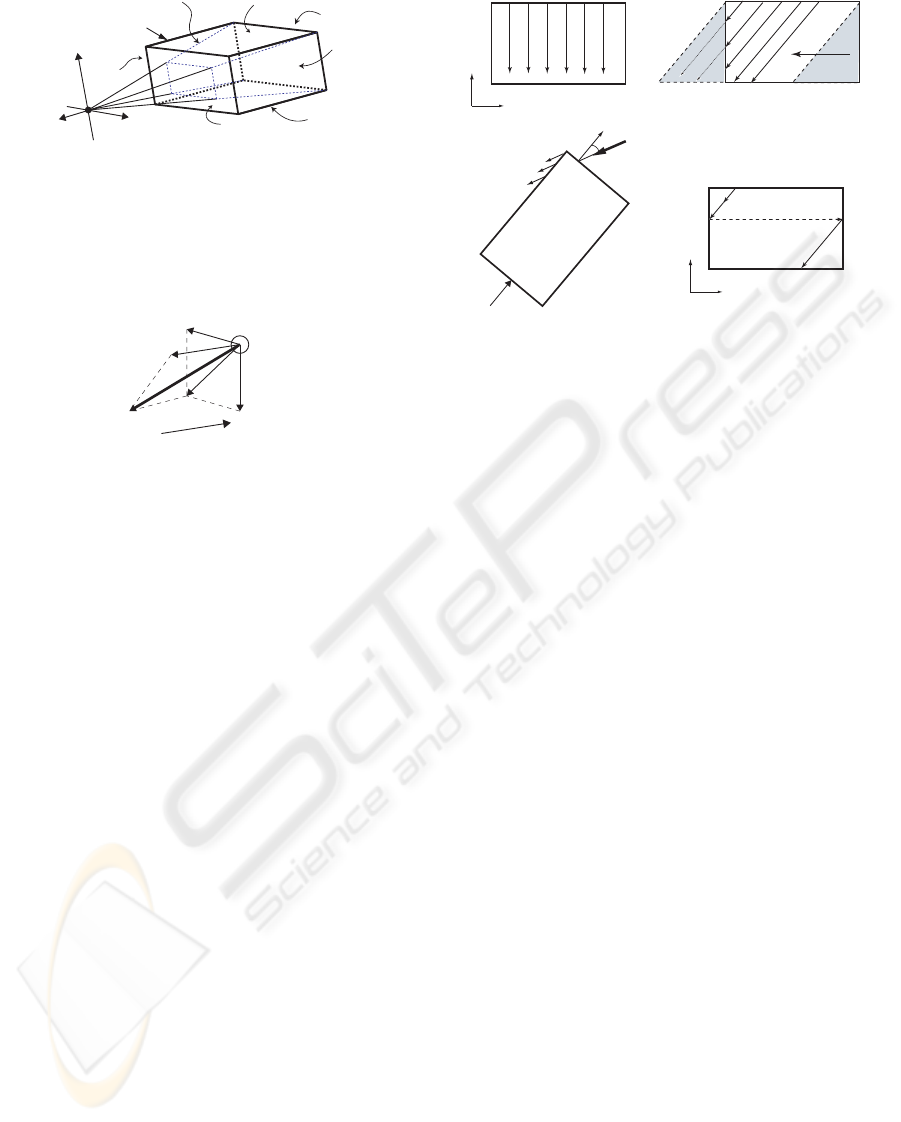
3 RAINDROP MOVEMENT
In this section, the computing and drawing method
for the trajectory of raindrops is described. The pro-
posed method regards only raindrops in the rectangu-
lar parallelepiped (RP, see Figure 3) located in front
of the viewpoint as a target for computing and draw-
ing. At first, let us explain how to compute the veloc-
ity vector of a raindrop including its apparent move-
ment due to camera movement. Then the effective
wrapping-around reuse of raindrops running over the
RP is shown.
3.1 Calculation of Velocity Vector
(1) Stationary Camera Model. The RP is defined as
a bounding box that including a part of the view vol-
ume, which is illustrated with bold lines in Figure 3.
We consider that every raindrop which is tracked its
trajectory exists only in this RP as described before.
According to the prior condition (1), the factors
affecting the raindrops’ movement are the gravity and
wind. Consequently, the velocity vector of a raindrop
(V
0
r
in Figure 4) can be computed by synthesizing
the following two factors. The first one is the
vertical falling velocity which reaches to the terminal
velocity, V
t
. The second one is the wind velocity, V
w
,
that is calculated by solving Navier-Stokes equation
(We discuss more in Section 4.2).
(2) Expansion to Dynamic-camera Model. In ap-
plications such as walk-through, the camera move-
ment can be classified into dolly, pan and tilt. The
camera movement causes an apparent movement of
raindrops on the screen. The proposed method trans-
lates this apparent movement into the velocity. Let
us explain with the case of dolly as shown in Fig-
ure 4. The dolly movement V
c
results in an apparent
movement with the opposite-direction velocity V
a
to
all raindrops. In the case of pan and tilt movements
that arise from the rotation of camera axis, they give
apparent movement with the opposite-rotation to all
raindrops. The proposed method regards the appar-
ent movement of raindrop caused by pan and tilt as a
set of linear movement on each frame. Consequently,
the apparent movement caused by camera movement
can be represented as a velocity vector. Then, final
raindrop’s movement, V
r
, is determined by synthesiz-
ing V
0
r
calculated by physics and V
a
given by apparent
movement as shown in Figure 4.
3.2 Three-dimensional
Wrapping-around of Raindrops
(1) Basic Idea. In the proposed method, only
raindrops that exist in the RP are regarded as a target
for computing and drawing. In a windless scene,
as shown in Figure 5(a), all raindrops arising from
REALISTIC RAIN RENDERING
275
right
bottom
far
top
left
near
view volume
RP*
x
y
z
camera coordinate system
* RP: rectangular parallelepiped for drawing
trajectory of raindrop
Figure 3: Geometry of the rectangular parallelepiped (RP)
for drawing a trajectory of a raindrop.
V
w
V
a
V
r
V
t
V’
r
raindrop
V
c
Figure 4: Determination of velocity vector of a raindrop.
the top face of the RP, T , fall down and reach the
bottom face, B. However, in case of windy scene as
depicted in Figure 5(b), some of raindrops run over
the side face before arriving at B and run into region
P, while region Q has no raindrop arising from the
top face. One of the solutions for this problem is to
extend the top face horizontally as a function of wind
speed. However it will bring redundant computation
of raindrops. The proposed method employs more
efficient method. Since we may consider that the
amount of raindrops in region P and Q are almost
the same with the geometrical property of the RP,
the raindrops running into region P can be reused as
raindrops going into region Q, which is a basic idea
of 3-D wrapping-around of raindrops. The details
will be described below.
(2) Face Attributes of RP. As illustrated in Fig-
ure 5(a), the top face, T , is usually given as an
attribute of raindrop-generating face, G, and the
bottom face, B, is given an attribute of raindrop-
vanishing face, V . Other four faces have the same
attribute of raindrop wrapping-around face. However,
in the case of large camera tilt and strong wind as
shown in Figure 5(c), there will be a problem that
all raindrops may fly out from the RP just after
being generated at the top face, T. Therefore, the
proposed method selects the face whose inward-
looking normal vector gives maximum inner product
with raindrop’s velocity vector (V
0
r
in Fig. 4) as the
raindrop-generating face, G, and its opposite face as
T (G)
B (V)
L R
(a)
T
B
L R
(b)
wind
P
Q
θ
B
T
F
N
(c)
(d)
T: To p
B: Bottom
G: Generating face
V: Vanishing face
x
y
V
G
P
0
P
1
P
2
S
1
S
0
P
3
x
y
x
1
x
2
L: Left
R: Right
N: Near
F: Far
velocity
vector
view
direction
Figure 5: 3-D Wrapping-around of the falling trajectory of
the raindrop.
the raindrop-vanishing face, V .
(3) 3-D Wrapping-around of Raindrops. Fig-
ure 5(d) illustrates 3-D wrapping-around for tracking
the raindrop trajectory. If a raindrop hits a wrapping-
around face (in this case S
0
), the raindrop is auto-
matically moved to the same position on the opposite
wrapping-around face (in this case S
1
) and continues
the same movement. In this example, only x coordi-
nate of the raindrop is changed from x
1
to x
2
as the
result of the 3-D wrapping-around processing. Rain-
drops can go under this processing more than once
until reaching the vanishing face.
4 RAINING LOCALITY
This section describes the way of representing raining
localities of intensity, density, movement and appear-
ance, which is one of the main contributions of the
proposed method.
4.1 Raindrop Generation with Local
High-density Distribution
In the situation of shower or heavy rain, we can see
cluster of raindrops with high intensity and high den-
sity moving. This paper develops a simple model for
rendering these non-uniform characteristics of rain-
ing scene. It is assumed that there are two kinds of
area in a raining scene. The first area has temporally-
and-spatially uniform characteristics, while the other
GRAPP 2008 - International Conference on Computer Graphics Theory and Applications
276
area does not. We employ a raindrop-generating
model that deals with these different areas separately.
To be more precise, this proposed model generates
raindrops uniformly in the RP discussed in section
3 and synthesizes local high-density distributions of
raindrops. This synthesis procedure provides blocky
placements of raindrop in the rendered space. The lo-
cal high-density distributions of raindrops should be
moved over the course of time due to its nature prop-
erty. On the other hand, as described in section 3, this
proposed method only tracks the trajectories of rain-
drop in the rectangle parallelepiped and renders them.
Consequently, in the local high-density distributions
of raindrops, one needs to consider only raindrops
whose initial positions are included in the generating
face of the RP. However, for example, in producing an
animation sequence where the view direction gradu-
ally moves upward from initial horizontal direction,
the raindrop-generating face changes as the viewing
line tilts. Therefore, we define local high-density dis-
tribution on another plane that is independent of the
raindrop-generating face on the RP.
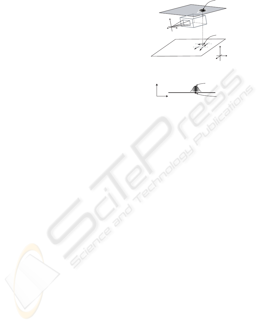
Figure 6 illustrates the raindrop-generating pro-
cedure of the proposed method. As shown in Fig-
ure 6(a), we define a plane S that is parallel to the
xz-plane of the world-coordinate system. As shown
in Figure 6(b), the local high-density distribution is
given as a form of Gauss distribution centered at the
reference point Q on the plane S. Since all rain-
drops have to be generated on the raindrop-generating
face of the RP in the proposed method, the raindrops
generated in the local high-density distribution are
projected onto the raindrop-generating face and are
merged with the raindrops normally generated in the
RP. The reference point Q is regarded as a particle
that is influenced by the wind effect and is moved like
a particle in the wind field. The computing method
of the wind vector influencing the reference Q is the
same with the computing method of the wind vector
influencing the raindrops that is described in the next
subsection. Since local high-density distributions can
be processed independently, it is possible to move
several distributions simultaneously in a scene.
This paper classifies raining types into three cat-
egories, that is, gentle rain, hard rain and heavy rain.
Each type has fundamental properties described in Ta-
ble 1. The proposed method assigns one of the fun-
damental properties of raining to the raindrops gen-
erated in the RP and assigns a heavier property to
the raindrops generated in the local high-density dis-
tribution. Consequently, two groups of raindrops in
the scene have distinctive differences in the terminal
velocity and their size, in addition to the raindrop-
generating density.
x
z
y
Q
X
Z
Y
camera coordinate
system
Q'
RP
S
world coordinate
system
(a)
x
y
S
Q
camera coordinate
system
distribution
of raindrops
(b)
Figure 6: Local high-density distribution of raining.
4.2 Local Wind Influence
We assume that the raindrops are influenced just hor-
izontally by the wind field and recognizes only two
factors as external forces on a raindrop as described
with the prior condition (1) in section 2.1, that is, the
vertical gravity and the horizontal wind influence. As
shown in Table 1, the vertical downward velocity is
assumed to be equivalent of a constant terminal ve-
locity depending on the degree of raining intensity.
On the other hands, the horizontal velocity is deter-
mined based on the two-dimensional fluid simulation.
These vertical-and-horizontal results are utilized for
computing the trajectories of raindrop. It should be
noticed that this simplified procedure is very efficient
for computing the unsteady wind field and its influ-
ence to the raindrop movement.
We employ a solving technique of Navier-Stokes
equations suggested by Stam (Stam, 1999) for simu-
lating two-dimensional wind field. A simulation field
is configured on the scene with enough area to deal
with changes in the field of view and the calculus of
finite differences is applied to its mesh representation.
At the mesh points, the wind velocity vectors are com-
puted at the frame rate. The wind velocity vector at
the sub-mesh points can be interpolated linearly based
on four values at the nearest surrounding mesh points
and it is used as the wind velocity vector, V
w
in Fig-
ure 4.
REALISTIC RAIN RENDERING
277

Table 1: Fundamental properties of three types of raining
intensity.
hard
gentle
heavy
type
4.0
rainfall (mm/h)
diamiter (mm)
terminal
velocity (m/s)
15.0
40.0
1.0
4.0
1.5
5.0
2.0
6.0
4.3 Raindrop Rendering Considering
Illumination Locality
It is indispensable to reflect the occluding condition
of the sky and cloudiness on the trajectories of rain-
drop with a simplified method. Since the image-based
method using the environment mapping technique for
representing the reflection to the surface of raindrops
leads to the shortage problem of dynamic range
as discussed in section 2, the illuminance due to
skylight is utilized for computing the reflection on
the raindrop surface. The following parts describe
a simplified rendering model for representing the
influence of the lighting environment on a raindrop,
the computation of the illuminance due to skylight,
and the procedure of producing an illuminance map.
(1) Raindrop Rendering Model. The intensity of light
arriving at the viewpoint comes through a raindrop,
I
V
, is expressed as the following equation based on the
intensity of light reflected at a point on the raindrop,
I
Ri
, and the intensity of light transmitted through the
rain drop, I
Ti
.
I
V
=
∑
i
(r
i
I
Ri
+ (1 − r
i
)I
Ti
)ω
i
, (1)
where r
i
is a reflection ratio t a point x
i
on the rain-
drop, ωi is a contribution of x
i
(
∑
i
ω
i
= 1.). It is well
known that the computation cost to obtain both I
Ri
and
I
Ti
is heavy. Then we set the following assumptions in
order to reduce computation cost for rendering rain-
drop considering locality of illumination:
• Since the major part of the I
V
consists of energy
which comes from the sky, the intensity of I
V
is
proportional to the illuminance due to skylight at
the location of the raindrop.
• Only the light comes from background of a rain-
drop whose direction is the same as I
V
, I
P
in Fig-
ure 7, is considered as a transmitted component.
Then, equation 1 can be re-written as follows,
I
V
= r
c
α
sky
E
sky
+ (1 − r
c
)I
T c
, (2)
where α
sky
is the coefficient to transform from
illuminance due to skylight, E
sky
to intensity of light,
I
T c
is intensity of light which arrives at the viewpoint
raindrop
P
V
I
R
I
T
I
V
I
P
Figure 7: Raindrop rendering model.
passing through the center of the raindrop, r
c
is the
reflection ratio of the light corresponding to I
T c
.
(2) Computation of Illuminance due to Skylight. The
proposed method calculates the illuminance due to
skylight, E
sky
considering with sky occlusion in the
same manner of (Tadamura et al., 1993) with the fol-
lowing equation.
E
sky
=
N
∑
i=0
M
∑
j=0
τ(i, j)L(i, j)H(i, j)∆S
i j
, (3)
where τ(i, j) is an attenuation ratio due to raining
related to the sky-element (i, j). Since it is assumed
that there is no directional difference of attenuation,
τ(i, j) can be a constant. L(i, j) is a luminance at
the sky-element (i, j), H(i, j) is a blocking function
that if the sky-element (i, j) is blocked (black pixels
in Figure 8(b) and (c)) it gives 0 otherwise (gray
pixels) 1. ∆S
i j
is the area onto which the sky-element
(i, j) is projected. In the proposed method, the
sky luminance L(i, j) is computed by ALL SKY
MODEL(Igawa et al., 2001) that can consider the
location of the sun even in the overcast-sky (see the
details in (Igawa et al., 2001)). Figure 8(a) and (b)
show the typical occluding condition of the sky, at a
place surrounded by tall buildings and a place where
there is no tall building, respectively. It should be
noted that the surrounding buildings determine the
occluding conditions. Therefore, the light intensity
coming through a raindrop at the two places differs
greatly.
(3) Illuminance Map. Computing the illuminance at
all positions of raindrops with the above procedure re-
sults in a huge load. Therefore, we employ a scheme
for reducing the computation load without keeping
the locality of the light intensity coming through
a raindrop based on the occluding condition of the
sky. In this scheme, at the mesh points used for
two-dimensional wind simulation, the illuminance is
computed in advance and the obtained illuminance is
stored in the data table. This data table is referred as
an illuminance map.
GRAPP 2008 - International Conference on Computer Graphics Theory and Applications
278
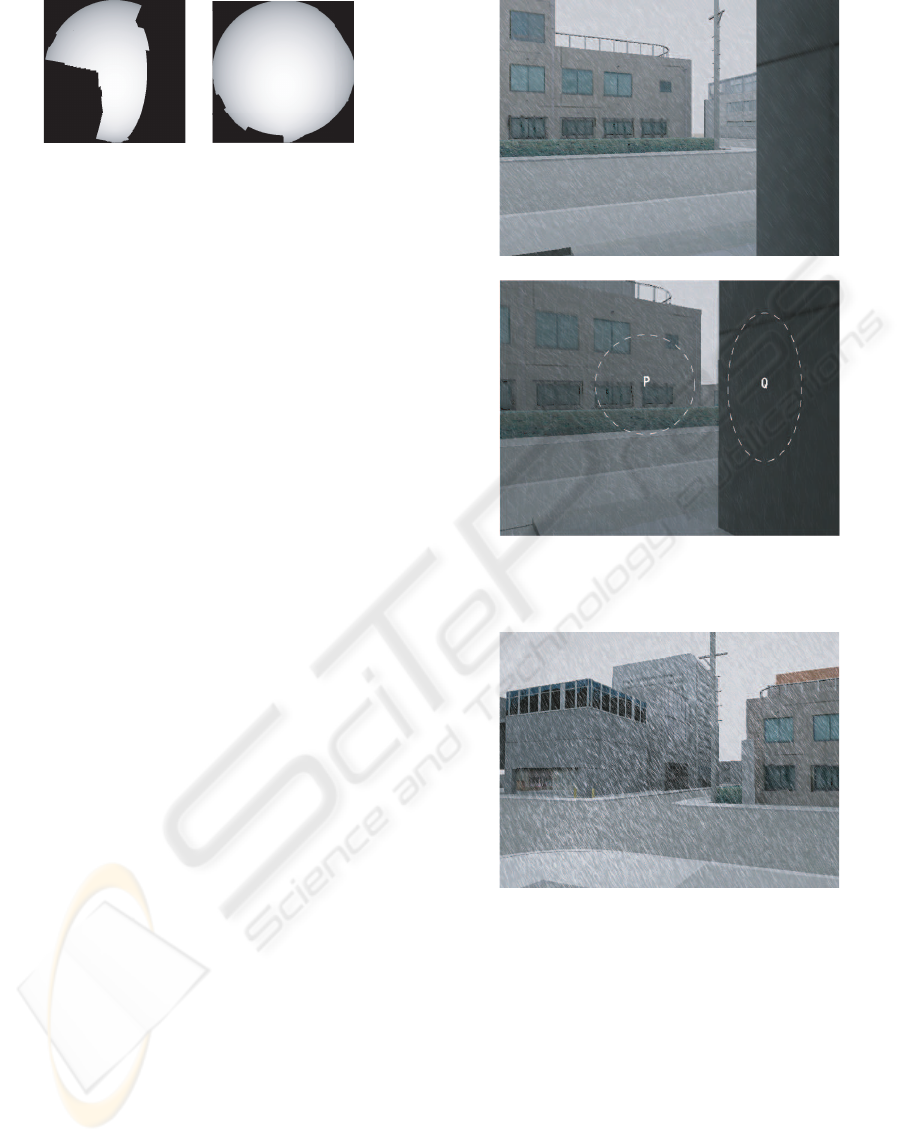
(a) (b)
Figure 8: Examples of the sky occlusion; (a)surrounded by
tall buildings; (b)no tall building.
5 RESULTS AND DISCUSSIONS
We implemented the proposed method described
above on a PC with Intel Pentium 4 2.8GHz pro-
cessor, nVIDIA GeForce 6600GT and 2GB RAM.
In order to obtain a raining animation, we prepared
sequence images which were generated by a 3D-CG
package software as back-ground images for rain. At
first, we will show an example for dealing with local-
ity of wind. Figure 9(a) is a scene obtained by apply-
ing conventional method, that is, a stable wind blows
with uniform direction and velocity over the scene.
Figure 9(b) is a frame of an animation created by the
proposed method treating with the temporal-spatial
locality of unsteady wind by solving Navier-Stokes
equation. Two portions of the image surrounded by
white broken line ellipses, P and Q, in Figure 9(b)
show the difference of the trajectory of raindrops.
The direction of the trajectory of the raindrops in Q
are quite different from the same potion of the Fig-
ure 9(a). Figure 10 shows a frame of an animation
for demonstrating the usefulness of non-uniform den-
sity and intensity of the rain distribution. We can see
the high density raindrops in the vicinity of the cen-
ter of the image. The animation allows us to inves-
tigate temporal movement of the high density rain-
drops. Figure 11 demonstrates the advantage of ren-
dering a raindrop with illuminance due to skylight.
The skylight around the sun is the brightest in the
whole sky even in the overcast sky. Figure 11(a) is
an example for a case that the high intensity portion
of the sky is not occluded by the buildings because of
high solar altitude, while bright potion is almost oc-
cluded by the buildings because of low solar altitude
in (b). These figures are noticed that illumination due
to skylight deeply affects on appearance of raindrop.
It takes about one second per frame to add rain tra-
jectories to the background image with our proposed
method. Since the proposed method draws the rain
streak with CPU, more than 70% of computation time
is consumed for scan-conversion of the rain streaks.
(a) A scene with uniform wind.
(b) A scene with non-uniform wind.
Figure 9: Effects of dealing with wind locality.
Figure 10: A scene with temporal-spatial localities of rain
intensity and density.
6 CONCLUSIONS
We have proposed a method for rendering the tra-
jectory of raindrops that can deal with both the
temporal-spatial localities of raining and arbitrary
camera movements. These localities include wind
velocity and direction, intensity and density of the
raindrops and light intensity coming through the rain-
drop. We employed 3-D wrapping-around of rain-
drops for efficient calculation of the trajectory of the
raindrops. 2-D wind field was simulated by solv-
REALISTIC RAIN RENDERING
279

(a) High solar altitude
(b) Low solar altitude
Figure 11: Comparison of the results with different solar
altitude.
ing Navier-Stokes equations and used for achieving to
represent temporal-spatial localities of wind. We used
a numerical sky luminance distribution model which
can consider the location of the sun for the overcast-
sky.
In order to use the proposed method to the real-
time application such as games and drive simulators,
we need to accelerate the rain streak drawing process
by using GPU. In future work, we will modify the
proposed method for utilizing GPU ability.
ACKNOWLEDGEMENTS
This research work was partially supported by the
Ministry of Education, Science, Sports and Cul-
ture of Japan, Grant-in-Aid scientific research(C)
19500084.
REFERENCES
Feng, Z., Tang, M., Dong, J., and Chou, S. (2005a). Real-
time rain simulation in cartoon style. In 9th Inter-
national Conference on Computer Aided Design and
Computer Graphics.
Feng, Z., Tang, M., Dong, J., and Chou, S. (2005b).
Real-time rendering of raining animation based on
the graphics hardware acceleration. In 9th Interna-
tional Conference on Computer Supported Coopera-
tive Work in Design, pages 734–739.
Garg, K. and Nayar, S. (2006). Photorealistic rendering of
rain streaks. In SIGGRAPH’06, pages 996–1002.
Igawa, N., Koga, Y., Matsuzawa, T., and Nakamura, H.
(2001). Development of all sky model of sky ra-
diance distribution under various atmospheric con-
ditions. In Istanbul 2001 International Lighting
Congress 2, pages 331–333.
Kaneda, K., Ikeda, S., and Yamashita, H. (1999). Animation
of water droplets moving down a surface. The journal
of visualization & computer animation, 10(1):15–26.
Reeves, T. W. (1983). Particle systems - a technique for
modeling a class of fuzzy objects. ToG, 2(2):359–376.
Rousseau, P., Jolivet, V., and Ghazanfarpour, D. (2006). Re-
alistic real-time rain rendering. Computers & Graph-
ics, 30(4):507–518.
Sato, T., Dobashi, Y., and Yamamoto, T. (2002). A method
for real-time rendering of water droplets taking into
account interactice depth of field effects. In IWEC’02,
pages 110–117.
Sims, K. (1990). Particle animation and rendering us-
ing data parallel computation. Computer Graphics,
24(4):405–413.
Stam, J. (1999). Stable fluids. In SIGGRAPH’99, pages
121–128.
Starik, S. and Werman, M. (2003). Efficient simulation of
rain in videos. In Texture 2003 Nice, pages 95–100.
Tadamura, K., Nakamae, E., Kaneda, K., Baba, M., Ya-
mashita, H., and Nishita, T. (1993). Modeling of
skylight and rendering of outdoor scenes. Computer
Graphics forum, 12(3):189–200.
Tatarchuk, N. (2006). Artist-directable real-time rain ren-
dering in city environments. In SIGGRAPH2006
Course Note 26, chapter 3, pages 23–64. ACM.
Wang, L., Lin, Z., Fang, T., Yang, X., and Kang, S.
(2006). Real-time rendering of realistic rain. In SIG-
GRAPH’06 Sketches.
GRAPP 2008 - International Conference on Computer Graphics Theory and Applications
280
