
MESH
SIMPLIFICATION USING DISTANCE LABELS FOR
VIEW-INDEPENDENT SILHOUETTE PRESERVATION
Susana Mata, Luis Pastor
Dept. de Arquitectura y Tecnolog
´
ıa de Computadores, Ciencias de la Computaci
´
on e Inteligencia Artificial
C. Tulip
´
an, s/n., 28933 M
´
ostoles, Madrid, Spain
Angel Rodr
´
ıguez
Dept. de Tecnolog
´
ıa Fot
´
onica, U. Polit
´
ecnica de Madrid
Campus de Montegancedo s/n, 28660 Boadilla del Monte, Spain
Keywords:
Computational Geometry and Object Modelling, Three Dimensional Graphics and Realism, Picture and Image
Generation.
Abstract:
Multiresolution modelling is a good method to achieve both quality and performance in the rendering of com-
plex scenes. Within this framework, the detection and preservation of outstanding features, such us silhouettes,
become very important. The goal of this paper is to present a technique based on Distance Transforms that
allows to classify the elements of the mesh according to their proximity to both the internal and the external
contours and makes use of this information for weighting the approximation error which will be tolerated dur-
ing the mesh simplification process. The approach used in this work precomputes silhouettes for a given set
of cameras and performs an estimation for any other point of view. The results obtained are evaluated in two
ways: visually and using an objective metric that measures the geometrical difference between two polygonal
meshes.
1 INTRODUCTION
Highly detailed polygonal meshes may contribute
to the generation of realistic renderings and physi-
cal simulations; however the high computation time
requirements may avoid fluent interactivity, result-
ing paradoxically in a reduction of realism. Con-
sequently, whenever computation time is a concern,
techniques which decrease the model’s polygon count
while keeping an acceptable visual appearance are de-
sirable.
Multiresolution modelling presents itself as a suit-
able solution by representing objects at different res-
olution levels and choosing the proper approxima-
tion according to the visualization conditions (Xia and
Varshney, 1996; Hoppe, 1997). Basic principles of
this approach were set by James Clark (Clark, 1976);
comprehensive surveys can be found at (Puppo and
Scopigno, 1997; Garland, 1999; Luebke, 2001; Lue-
bke et al., 2003; De Floriani et al., 2005). Within
this framework, the detection and preservation of fea-
tures that drive the observer’s attention become cru-
cial . Silhouettes constitute an example of such fea-
tures, since they are known to be critical for the final
visual quality appreciated by our visual system (Lue-
bke and Erikson, 1997).
The goal of this paper is to propose a new tech-
nique that allows taking into account the proximity of
a mesh element to the mesh’s contour for weighting
the approximation error which will be tolerated dur-
ing the simplification process. More specifically, the
contributions of this work can be briefly summarized
as follows:
• Applying a Distance Transform for detecting the
proximity of mesh elements to the silhouette for a
set of points of view.
• Extending the detection technique in order to in-
clude internal silhouettes.
• Using the precomputed proximity measure as an
error tolerance map in order to guide a simplifica-
tion technique.
• Interpolating the proximity to the silhouette for a
new point of view not considered in the precom-
puted set of cameras.
The rest of the paper is organized as follows:
Section 2 presents a short overview of some previ-
ous work related to mesh simplification algorithms
and the different approaches to identify and preserve
5
Mata S., Pastor L. and Rodríguez A. (2008).
MESH SIMPLIFICATION USING DISTANCE LABELS FOR VIEW-INDEPENDENT SILHOUETTE PRESERVATION.
In Proceedings of the Third International Conference on Computer Graphics Theory and Applications, pages 5-14
DOI: 10.5220/0001096300050014
Copyright
c
SciTePress

the model’s silhouette. A brief introduction to basic
concepts of digital Distance Transforms and Multi-
Tessellation is also included. Section 3 describes the
proposed approach, while Section 4 shows some ex-
perimental results. Finally the conclusions and future
work are presented in Section 5.
2 PREVIOUS WORK
2.1 Mesh Simplification
Many mesh simplification techniques have been pro-
posed during the last years. Among the methods
based on objective metrics, work has been done in or-
der to incorporate other attributes besides geometry
like color, texture or normals (Garland and Heckbert,
1998; Cohen et al., 1998). Perceptual metrics have
also been developed (O’Sullivan et al., 2004; Cheng
and Boulanger, 2005); Lindstrom and Turk use an im-
age metric to guide the simplification process (Lind-
strom and Turk, 2000). Reddy introduced a percep-
tive model to guide the selection of the appropriate
level of detail (Reddy, 1997). (Luebke, 1998) de-
fined a contrast sensitivity function that predicts the
perception of visual stimuli. Some of the perceptu-
ally driven simplification methods explicitly pursue a
good silhouette preservation, defining normal cones
(Williams et al., 2003). Good silhouette approxi-
mation through contour computation in image space
has also been researched (Raskar and Cohen, 1999;
Sander et al., 2000).
The approach presented here not only identifies
the objects’ silhouette. It also performs an explicit
classification of the mesh’s elements in object space,
depending on their proximity to the contour from a
given point of view.
The final goal of a simplification process may be
either to obtain a discrete set of simplified models or
to create a continuous multiresolution model. In this
last case, a hierarchical data structure is created in a
preprocessing stage and will be queried at run time
in order to extract the desired level of detail (Hoppe,
1997; De Floriani et al., 1997).
The Multi-Tessellation method, originally called
Multi-Triangulation, was introduced by De Floriani
et al. (De Floriani et al., 1997). It provides a general
multiresolution framework for polygonal meshes of-
fering several attractive features like selective refine-
ment, locality or dynamic update (De Floriani et al.,
1998). The Multi-Tessellation, MT for short, is a hi-
erarchical model that can be generated during an off-
line simplification process and queried at run time
for extracting a simplified mesh fulfilling some de-
fined restrictions. Some useful restrictions are already
implemented in the distributed package (Geometric
Modeling and Computer Graphics Research Group,
2005), while the implementation of new ones can be
easily done.
The MT package has been used in this work for
implementing the extraction of a simplified model
that takes into account the visual relevance of a model
region. Its flexibility and implementation conve-
nience have been some of the underlying reasons for
this choice.
2.2 Digital Distance Transforms
Measuring the distance between image elements may
be of interest for further processing in many image
analysis applications. Basics concepts regarding dig-
ital distances can be found in (Rosenfeld and Pfaltz,
1966; Rosenfeld and Pfaltz, 1968; Borgefors, 1984).
The application of a Distance Transform to a
binary image produces as output a distance image
where each element of this distance-image is assigned
a distance label. For any element its label stores
a value indicating its closest distance to the back-
ground. Therefore, the computed distance image can
be seen as a grey-level image where the intensity level
identifies the minimum distance to the complement of
the object.
A distance transform can be computed in two
steps by propagating local distances over the image;
this is true for 2D, 3D and higher dimensions (Rosen-
feld and Pfaltz, 1966). Initially, the elements belong-
ing to the object are set to infinity and the elements
belonging to the background are set to 0. In the case
of a 2D image, during the first step the image is ana-
lyzed from top to bottom and from left to right. Dur-
ing the second step, the image elements are visited
from right to left and from bottom to top. Each el-
ement is assigned the minimum value between itself
and the already visited neighbors incremented by their
connectivity weight.
Distance transforms and some variations of them
in combination with other image processing tech-
niques can be applied for representing and analyzing
3D objects in multiple applications (Nystr
¨
om, 1997;
Svensson, 2001; Sintorn, 2005; Jones et al., 2006).
Distance fields have also been applied in computer
graphics environments, such as in collision detection
(Teschner et al., 2004), and have been implemented
with graphics hardware (Sud et al., 2006).
However, digital distance transforms can be used
in other fields that have not been explored so far. The
work presented here aims to open a way for new ap-
GRAPP 2008 - International Conference on Computer Graphics Theory and Applications
6

plications of Distance Transforms within computer
graphics environments.
3 METHOD DESCRIPTION
The approach followed here classifies the mesh faces
or vertices according to their proximity to the silhou-
ette, as seen from a specific point of view. The classi-
fication process uses a Distance Transform, computed
over the mesh elements’ projection on the visualiza-
tion plane. This transform provides for each element
its distance to the projected contour, being useful for
extracting the mesh elements which compose or are
located near the mesh silhouette for a particular point
of view. The distance of the mesh elements to the
projected contour (measured in image space) is en-
coded as distance-labels which are assigned to the
mesh, producing this way a view-dependent tagged
mesh.
If this process is applied for a number NC of cam-
eras, it will produce NC collections of precomputed
distance-labels, one collection for each camera. Since
these precomputed distance-labels are only valid for
the point of view from which they were extracted, an
interpolation technique is applied for any other point
of view.
The tags of the polygonal mesh elements, either
assigned or interpolated, can then be used in different
ways to guide the simplification process, providing a
criterion for modifying locally the approximation er-
ror allowed in areas close to the contour.
It must be highlighted that the computation of
distance-labels for a set of cameras is performed in a
pre-processing stage, producing a set of labels which
will be used later on during the simplification stage.
Figure 1 depicts a scheme of the whole process and
Alg. 1 collects its pseudo-code description. The fol-
lowing Sections describe each of the method’s stages.
3.1 View-dependent Distance Labels
Computation
Silhouettes are view-dependent features. For that rea-
son, their extraction must be done from a certain point
of view. This method’s first stage is entirely carried
out as preprocessing. As a result, a set of distance
labels is obtained, encoding the proximity of every
mesh element to the contour for a fixed point of view.
Since this analysis will be carried out for a set of NC
points of view, the final result will be NC sets of la-
bels, being each set valid for the analyzed point of
view. Subsections 3.1.1–3.1.4 give a detailed expla-
nation of this process.
3.1.1 Mesh Mapping
Given a visualization plane, the 3D mesh is projected
on it by applying the proper projection matrix to the
coordinates of each vertex. In order to extract the ob-
ject’s silhouette, it is necessary to create a binary im-
age where distance measurements can be made. For
that purpose the visualization plane is partitioned into
cells forming a grid which can be seen as a 2D digi-
tal image. The number of cells making up the grid is
analogous to the image resolution; consequently the
parameterization of this value allows the analysis at
different resolutions.
Every face belonging to the projected polygonal
mesh is tested to find the cells of the 2D grid with
which it intersects.
A data structure is updated where every grid ele-
ment keeps track of the faces intersecting with it. This
way, the posterior backprojection of distance values
is straightforward. This procedure is computationally
expensive, but affordable as pre-processing.
3.1.2 Binary Image Computation
In the case that only the external contour has to be pre-
served, the binary image is extracted from the grid oc-
cupancy information, setting as object every cell with
any face mapping over it. Object pixels adjacent to the
background will determine the external silhouette.
However, since internal silhouettes are known to
have a big impact in the visual quality perceived by
a human observer, their preservation is also desirable.
Detection of internal contours cannot be directly per-
formed in image space, but it can be easily carried
out in object space. By checking the angle formed
between a face normal and the visual vector it can
be concluded whether it is a frontfacing or backfac-
ing face. All the vertices shared by backfacing and
frontfacing facets are tagged as silhouette. With this
information, the occupancy binary image is modified
in the following way: an object pixel is set as back-
ground if a face containing a silhouette vertex projects
onto it. With this modification, the silhouette (internal
and external) will be determined by the background
pixels which are adjacent to an object pixel. Figure 2
illustrates the extraction of both internal and external
contours.
3.1.3 Distance Transform Computation
Once the 2D image is obtained, the next stage consists
in obtaining a distance image by applying a distance
transform to the binary image. The result is a new
image where the assigned intensity values increase as
the pixel gets further away from the background.
MESH SIMPLIFICATION USING DISTANCE LABELS FOR VIEW-INDEPENDENT SILHOUETTE
PRESERVATION
7
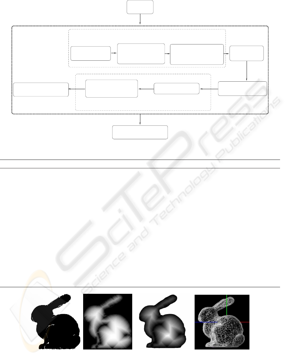
Original
3D mesh
3D Mesh simplification
Set of distance labels
for the processed view
Binary image
computation
2D View
selection
3D Mesh projection
over the selected
view plane
the mesh projection
configurable grid over
Overlapping of the 2D
Label backprojection
over original 3D mesh
Distance Transform
computation
For each point of view
Mesh labelling
Mesh mapping
2D Grid labelling
Figure 1: Mesh simplification stages.
Algorithm 1 Pseudo-code of the pre-processing stage.
1: {INPUTS: 3D mesh, visualization parameters}
2: {OUTPUT: Collection of view-dependent labels}
3: Create a 2D grid over the visualization plane of the 3D input mesh
4: for all precomputed point of view do
5: for all grid-cells do {It is computed in a pre-processing stage}
6: Label each grid-cell with the 3D mesh vertices that project onto it
7: end for
8: Extract a binary image using the grid-cells occupation {Each pixel represents a grid cell}
9: Compute a Distance Transform over the binary image
10: Assign to each grid-cell the distance value of its associated pixel
11: for all grid-cells do {Assign labels to 3D vertices}
12: Backproject its distance value to all the 3D mesh vertices that project onto it and obtain a view-dependent
set of labels
13: end for
14: end for
15: Store distance labels together with the point of view parameters
(a) Internal and exter-
nal contours extracted
in 3D space.
(b) Distance Trans-
form.
(c) Distance labels back-
projection.
(d) Simplification
preserving the silhouette.
Figure 2: Extraction of both internal and external contours.
GRAPP 2008 - International Conference on Computer Graphics Theory and Applications
8

3.1.4 Mesh Labelling
At this point, the distance of an object pixel to the
background has already been computed. Previously,
the correspondences between pixels and the facets
mapping into them have also been calculated. There-
fore, the labelling of every face with a value repre-
senting its distance from the background is a simple
process. The distance label of a pixel, which is equiv-
alent to a grid cell, is assigned to all the faces that
intersect with the cell.
As a result a set of labels is obtained, where every
label belongs to a face and represents its proximity to
the contour for the analyzed point of view.
The same approach may be followed when the dis-
tance label is assigned to vertices or edges instead of
faces. Figure 3 shows the results of backprojecting
the distance values onto the mesh. Fig. 3(a) and 3(d)
show a rendered view of the original mesh. Fig. 3(c)-
(b) and 3(e)-(f) represent the same meshes under dif-
ferent points of view. The grey levels in the images
represent distance to the silhouette (lighter intensities
represent higher distances to the contour).
3.2 Distance Labels Interpolation for
New Points of View
Whenever the point of view from which the model is
to be rendered does not belong to the preprocessed set
of views, there is no valid set of distance-labels pre-
computed. In this case, the approach followed in this
work interpolates a new set of distance-labels from
the precomputed ones.
Two approaches have been implemented: the first
one consists in using the labels from the closest pre-
computed view; the second one interpolates for every
vertex v
j
the labels of the same v
j
in the n closest
views in the following way: Let PV ={PV
0
,..PV
NC
}
be the set of precomputed points of view; {PV
i
.labels}
the set of labels precomputed for the point of view
PV
i
; PV
i
.labels
v
j
the label of the vertex v
j
for the
point of view PV
i
; and finally, PV
c
the current
point of view, for which a set of labels is needed.
Then,
if PV
c
∈ PV then
PV
c
.labels are valid labels
else
Let {PV
k
..PV
n
} be the subset of n closest pre-
computed points of view
for j = 1 to nv do {nv is the number of vertices
of the mesh}
PV
c
.labels
v
j
=
∑
n
k=1
(PV
k
.labels
v
j
)/n
end for
end if
This way a new set of distance-labels is obtained.
Since this estimation is performed in real time, com-
putational efficiency is highly desired. For this rea-
son, the precomputed set of views are regularly dis-
tributed, allowing the detection of the closest views to
take a constant time.
At this point, a tagged mesh can be obtained for
any point of view, using either precomputed distance-
labels or estimated ones.
3.3 Mesh Simplification
The method’s last stage is also the final goal of the
whole process, where the extracted distance values
are used for mesh simplification purposes.
The use of the distance labels depends on the
selected simplification technique. The work pre-
sented here has been based on the Jade approach,
a vertex decimation technique based on global er-
ror (Ciampalini et al., 1997). The distance infor-
mation is computed for the vertices of the original
mesh. Since the vertices belonging to a simplified
model are a subset of the original mesh, the precom-
puted distance labels are valid for any level of detail.
Multi-Tessellations obtained through the application
of the Jade method are freely distributed with the MT-
Package.
The proximity of every facet to the contour is
taken into account in the extraction stage. This means
that for a given error threshold, the error allowed in
regions close to the silhouette is reduced according to
a predefined law.
The implemented solution, requires the definition
of two parameters:
• Distance interval: range of distance labels which
identify the region where a more accurate approx-
imation is desired.
• Error factor f : the purpose of this parameter is to
define a lower error threshold for the portion of
the mesh within the region of interest.
The width of the contour area can be simply mod-
ified by changing the range of distance labels that
define the region of interest. In our case, the range
is defined by setting a threshold over the minimum
distance of the vertices belonging to a face. Given
a distance threshold, and a vertex v
j
of triangle t
i
(∀t
i
∈ 3D mesh):
if PV
c
.labels
v
j
≤ distance threshold then
t
i
∈ contour
else
t
i
6∈ contour
end if
MESH SIMPLIFICATION USING DISTANCE LABELS FOR VIEW-INDEPENDENT SILHOUETTE
PRESERVATION
9
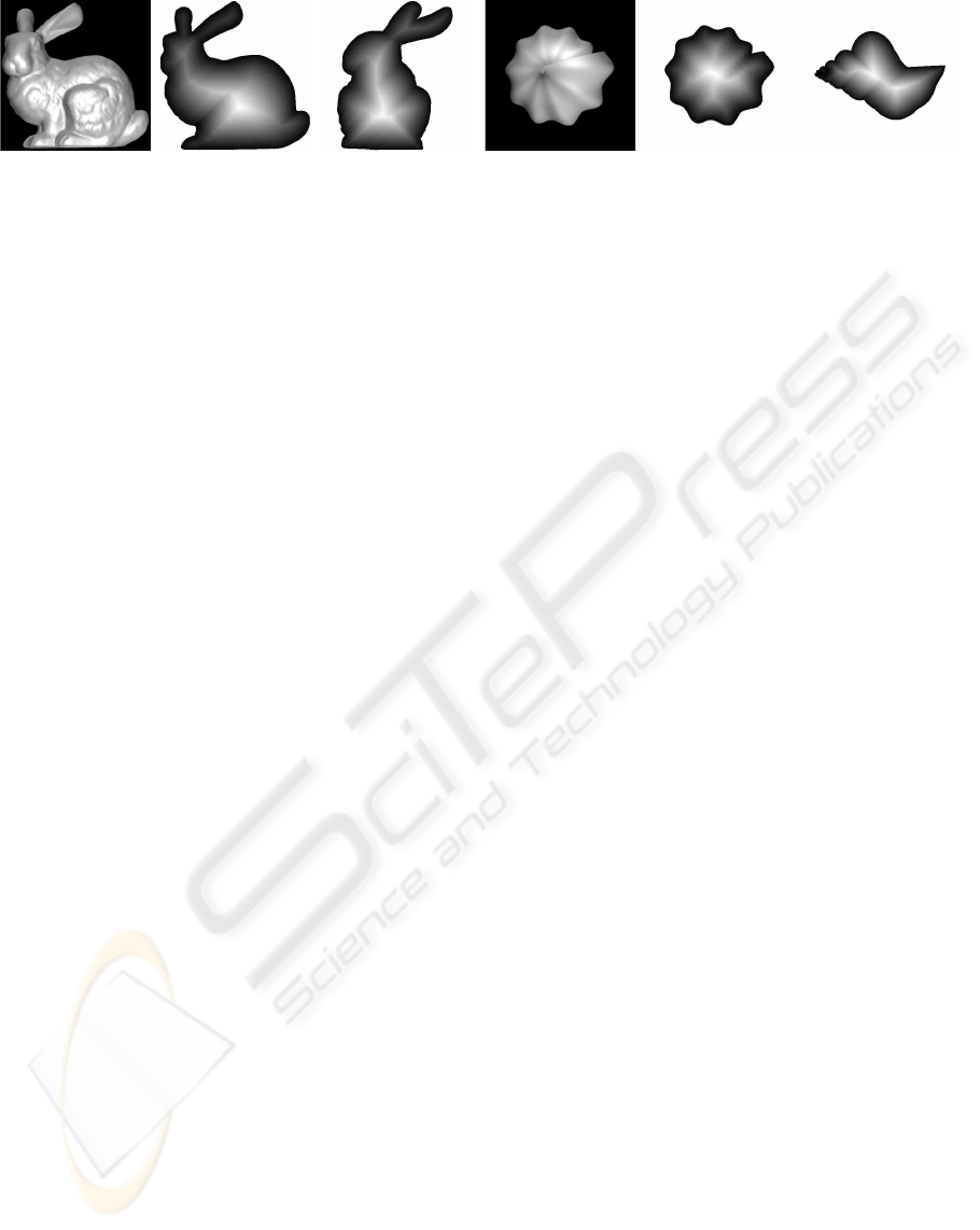
(a) Original Bunny
mesh.
(b) Distance com-
puted for the orien-
tation shown in Fig.
(a).
(c) Distance com-
puted for mesh in
Figure (a) under ro-
tation .
(d) Original shell
mesh.
(e) Distance com-
puted for the orien-
tation shown in Fig.
(d).
(f) Distance com-
puted for mesh in
Figure (d) under ro-
tation.
Figure 3: Backprojection of distance values over the 3D model. Mesh vertices color represent the backprojected distance
label with grey levels proportional to the distances to the external silhouette.
Remember that PV
c
is the current point of view and
PV
c
.labels have been extracted following the algo-
rithm described in section 3.2.
The error factor allows to refine the quality of
the approximation in the contour region taking into
account the threshold error fixed for the rest of the
model. Given a global allowed error e we can define
a more restrictive error that will be tolerated in the
contour region. Given the restriction factor f < 1, the
allowed error e
a
will be computed in the following
manner:
if t
i
6∈ contour then
e
a
= e
else
e
a
= e · f
end if
If the allowed error is uniform along the model, then
e
a
(t
i
) = e ∀t
i
∈ 3D mesh
Again, other error functions are also feasible.
4 RESULTS
The experimental results presented in this section
were obtained by applying the technique previously
described to Multi-Tesselations either distributed to-
gether with the MT-Package or generated from avail-
able surface models. The precomputed collection of
distance-labels has been obtained from a regular dis-
tribution of orthographic cameras over a bounding
sphere sampled every 15 degrees. The results pre-
sented in figure 4 show simplified models obtained
by imposing a restrictive error threshold over the sil-
houette, setting the error factor to 0. This means that
no error is allowed on the region of interest. It can be
seen that the rest of the mesh is coarser (it has suffered
a strong simplification process), while the density of
triangles over the silhouette is extremely high. Polyg-
onal meshes rendered in blue correspond to precom-
puted points of view, while meshes rendered in red
color are interpolated ones.
Figures 4 and 5 show the transition between two
precomputed points of view, making use of the closest
precomputed camera, while figure 6 shows the same
transition interpolating between the four closest pre-
computed cameras. It can be noticed in the video ac-
companying the paper that transitions are smoother
when using interpolated distance-labels. However,
the fact that the thickness of the contour can be pa-
rameterized, allows to work with wider silhouettes,
decreasing this way the perceived changes between
consecutive views. This effect can be better appre-
ciated in figures 4 and 5 that show the simplification
of the mesh obtained by imposing a restrictive error
threshold over the silhouette and varying the distance
interval. In both cases, the error factor was set to 0,
meaning that no error is allowed on the external con-
tour. Using greater error factors would result in sil-
houettes with greater approximation errors as it can
be noticed in Fig. 7(a) and 7(b). The region of interest
(the mesh portion considered to be near the silhouette)
is made up of faces whose vertices have a minimum
distance label less than or equal to 2 (Fig. 4) and less
than or equal to 4 (Fig. 5). It can be seen that the rest
of the mesh is coarser (it has suffered a strong simpli-
fication process), while the density of triangles over
the silhouette is extremely high.
In addition to a visual inspection, an objective
measurement of the approximation error has also been
performed. The difference between the two polygonal
meshes to be compared is computed following an ap-
proach similar to (Aspert et al., 2002): given a mesh
M1 and a coarser approximation M2, for every vertex
of M1 the minimum distance to the faces belonging
to M2 is computed. A visual representation of the
deviation is shown by coloring M1 with a predefined
color palette. Figure 7(c) presents the results of mea-
suring the difference between the original model and
the simplification extracted in figure 7(a). Figure 7(b)
measures the difference between the original model
and a homogeneous LOD extracted over the whole
GRAPP 2008 - International Conference on Computer Graphics Theory and Applications
10
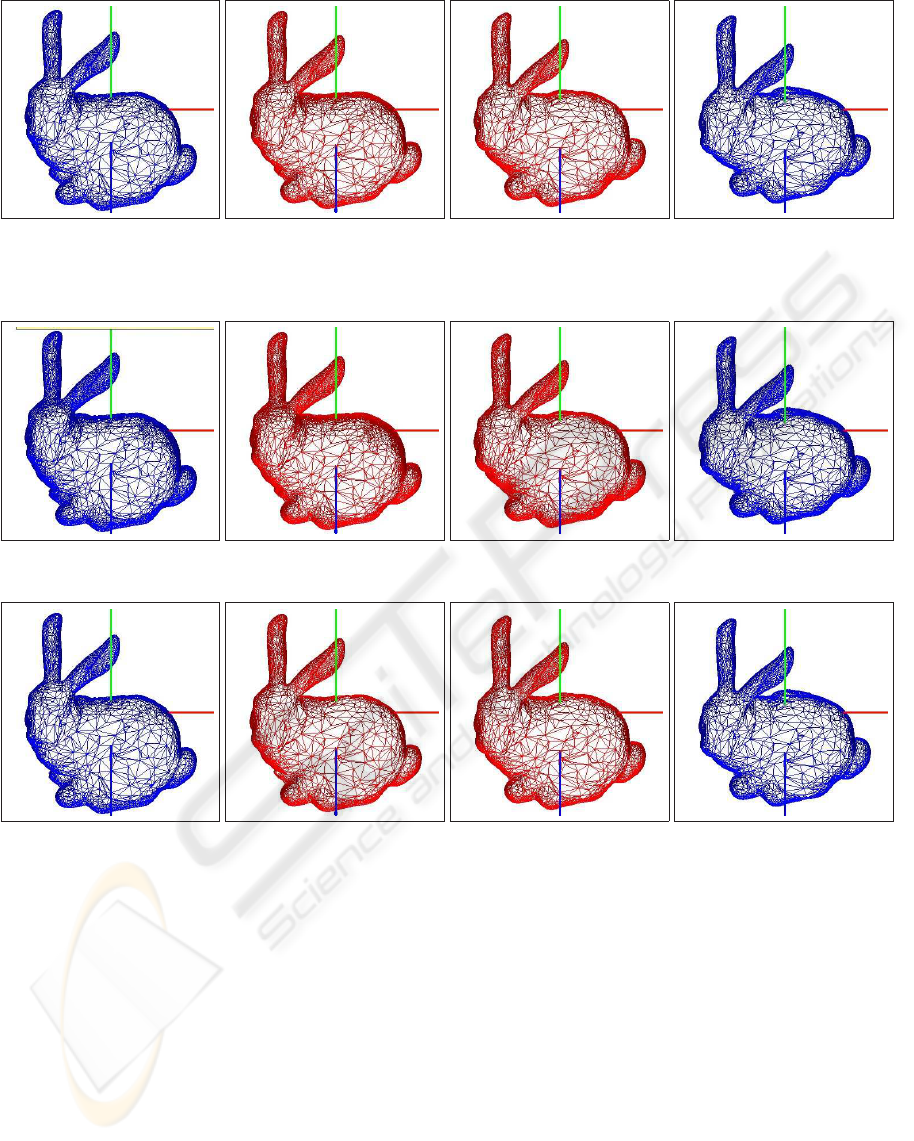
Figure 4: Transition between precomputed points of view (in blue) showing the extracted silhouettes for new points of view
(in red) using the closest view. Bunny with a rotation over the X axis of θ = 45
o
, θ = 50
o
, θ = 55
o
and θ = 60
o
setting
distance interval=2.
Figure 5: Same experiment of Fig. 4 setting distance interval=4.
Figure 6: Same transition of Fig. 4 interpolating from the 4 closest views.
model using the same global error allowed in 7(c).
From the error distribution it can be concluded that
the approximation in the silhouette is quantitatively
better with our method. Regarding computational is-
sues, cost in terms of memory requirements is of one
extra value per vertex and per precomputed camera.
By delimiting the sector where the observer next po-
sition will fall into, the number of cameras in memory
may be noticeably decreased. With respect to com-
putational cost, it has to be noted that all the heavy
computation is performed at pre-processing time. The
most expensive step is the mesh mapping over the 2D
grid, in order to collect the information needed for
backprojecting the distance values. Efficient imple-
mentations for these operations using spatial data par-
titioning could be considered.
Execution time measures have been acquired in
order to compute the overload of managing distance-
labels with respect to extracting a simplification from
a Multi-Tessellation without distance-labels. In both
cases, the parameters have been set in such a way
that the extracted meshes are at full-resolution, pro-
ducing this way the same load for the rendering stage.
With this experiment, measured times do not take into
account the advantage of multiresolution modelling,
that would result in the rendering a model with less
number of triangles. Table 1 shows the total time
spent in extracting a LOD from a distance-labelled
mesh versus the total time required for extracting an
homogeneous mesh of the same number of faces. Ta-
MESH SIMPLIFICATION USING DISTANCE LABELS FOR VIEW-INDEPENDENT SILHOUETTE
PRESERVATION
11
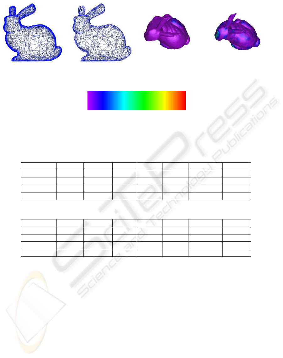
(a) Simplified model with
f = 0 and distance interval=4.
(b) Simplified model with
f = 0.2 · e and distance inter-
val=4.
(c) Approx. errors of 7(a)
compared to the original
mesh.
(d) Approx. error for a LOD
using the same global error as
in 7(a) .
Min. value=0 Max. value=1.273
(e) Color palette used for representing ap-
proximation errors.
Figure 7: Simplified models modifying the error factor. Visual representation of approximation error rendered under rotation
for a better perception of values.
Table 1: Statistics data extracted from executions using the closest precomputed point of view.
Model # facets TT (ms) PLI % PES % PRS % TTH (ms) OAH %
Shell 46550 45,65 0,04 23,85 76,10 43,84 3,96
Bunny 69451 69,22 0,02 24,65 75,32 66,91 3,33
Mannequin 204957 208,65 0,01 19,49 80,50 204,74 1,87
Sphere 360612 430,11 0,00 22,77 77,23 418,88 2,61
Table 2: Statistics data extracted from executions interpolating between the 4 closest points of view.
Model # facets TT (ms) PLI % PES % PRS % TTH (ms) OAH %
Shell 46550 55,17 17,10 20,02 62,88 44,22 19,84
Bunny 69451 82,39 16,24 20,97 62,79 66,93 18,76
Mannequin 204957 279,51 16,87 16,64 66,49 227,96 18,44
Sphere 360612 465,15 16,03 18,70 65,27 374,94 19,39
ble 1 also shows the percentage of the total time spent
in obtaining the closest view’s labels, extracting a
level of detail from the multi-tessellation, and render-
ing the final model. It can be observed that a very
small part of the total time is spent in getting distance-
labels for the current view. Table 2 shows the same
execution times as Table 1 measured interpolating be-
tween the 4 closest cameras.
It can be observed that using the closest camera
results in a lower overload (OAH < 4 %), since the
estimation of labels for new points of view is com-
putationally lighter. An additional advantage is the
fact that the extra time required for finding the closest
point of view is constant, independently of the size of
the mesh.
The notation used in Tables 1 and 2 is the follow-
ing:
TT: Total execution time (ms).
TTH: Idem considering an homogeneous LOD.
PLI: % of total execution time involved in accessing
the valid or interpolated distance-labels.
PES: Idem involved in the extraction of a LOD from
the multi-tessellation.
PRS: Idem involved in the rendering of the extracted
mesh.
OAH: Overhead introduced by using the proposed
method versus obtaining an homogeneous LOD
from the multi-tessellation.
The computer used in the tests was a 3.2 GHz Pen-
tium IV CPU with 1 GB of main memory and a
general purpose graphics card (NVIDIA GEFORCE
7800 GTX).
GRAPP 2008 - International Conference on Computer Graphics Theory and Applications
12

5 CONCLUSIONS AND FUTURE
WORK
Simplification algorithms are usually guided by some
criteria in order to select which elements of the mesh
shall be removed or replaced. Introducing precom-
puted distance labels as part of the guiding metrics is
a straightforward process, opening a new way to de-
sign a set of techniques which are useful for includ-
ing a wide range of criteria in mesh simplification al-
gorithms. Additionally, the approach presented here
can be applied in order to achieve higher resolution in
other relevant regions besides the silhouette, such as
visually outstanding areas, or semantically important
parts.
The results presented here suggest that the use
of distance information is a promising approach for
mesh simplification techniques, since adding distance
labels to mesh elements provides more information
than the conventional methods based on the extrac-
tion of the silhouette edges. This fact becomes patent
in the examples shown, where it can be seen that
by increasing the width of the preserved contour, the
quality of the silhouette in interpolated views also in-
creases. This flexibility in parameterization of con-
tour’s width, makes also possible to use the closest
view instead of interpolating between the n-closest
views, resulting in a valuable saving of computational
time.
The proposed technique may be easily adapted to
a wide range of simplification methods, since distance
information can be assigned to any element of the
mesh (vertices, edges or faces). This fact implies that
the nature of the basic underlying operator (vertex re-
moval, edge collapse, etc) does not impose additional
limitations. Furthermore, the applicability of distance
labels goes from off-line simplification processing to
run-time selective refinement.
Simplification techniques have a wide range of ap-
plications in leisure, science, industry, arts, etc. All of
them can benefit from the improvements in the quality
of the simplified models.
The work presented here may be extended in the
following ways:
• Integrating distance to the silhouette into other
mesh simplification methods besides the multi-
tessellation.
• Applying different error factors to internal and ex-
ternal contours.
• Estimating changes in the position of the point of
view, allowing the computation of distance-labels
in advance.
• Performing an analysis of variability between
points of view, in order to optimally redistribute
the precomputed cameras.
ACKNOWLEDGEMENTS
This work has been partially funded by the the
Spanish Ministry of Education and Science (grant
TIN2007-67188) and Government of the Community
of Madrid (grant S-0505/DPI/0235; GATARVISA).
The authors also thank to the Geometric Mod-
elling and Computer Graphics Research Group for
distributing the MT-Package.
REFERENCES
Aspert, N., Santa-Cruz, D., and Ebrahimi, T. (2002). Mesh:
Measuring error between surfaces using the hausdorff
distance. In Proceedings of the IEEE International
Conference in Multimedia and Expo (ICME), vol-
ume 1, pages 705–708. ISBN 0-7803-7304-9.
Borgefors, G. (1984). Distance transformation in arbitrary
dimensions. Computer Vision, Graphics and Image
Processing, 27:321–345.
Cheng, I. and Boulanger, P. (2005). A 3D perceptual met-
ric using just-noticeable-difference. In Proceedings
of Eurographics 2005, pages 97–100. Eurographics.
ISSN 1017-4656.
Ciampalini, A., Cignoni, P., Montani, C., and Scopigno, R.
(1997). Multiresolution decimation based on global
error. The Visual Computer, 13(5):228–246. ISSN
1432-2315.
Clark, J. H. (1976). Hierarchical geometric models for visi-
ble surface algorithms. Communications of the ACM,
19(10):547–554. ISSN 0001-0782.
Cohen, J., Olano, M., and Manocha, D. (1998).
Appearance-preserving simplification. In Proceedings
of SIGGRAPH’98, Annual Conference Series, pages
115–122. ISBN 0-89791-999-8.
De Floriani, L., Kobbelt, L., and Puppo, E. (2005). A sur-
vey on data structures for level-of-detail models. In
Dodgson, N. A., Floater, M. S., and Sabin, M. A., edi-
tors, Advances in Multiresolution for Geometric Mod-
elling, Series in Mathematics and Visualization, pages
49–74. Springer Verlag, Berlin. ISBN 3-540-21462-3.
De Floriani, L., Magillo, P., and Puppo, E. (1997). Building
and traversing a surface at variable resolution. In Pro-
ceedings of IEEE Visualization 97, pages 103–110.
IEEE Computer Society Press. ISBN 0-8186-8262-0.
De Floriani, L., Magillo, P., and Puppo, E. (1998). Efficient
implementation of multi-triangulations. In Proceed-
ings of IEEE Visualization VIS’98, pages 43–50. IEE
Copmuter Society Press. ISBN 0-8186-9176-X.
MESH SIMPLIFICATION USING DISTANCE LABELS FOR VIEW-INDEPENDENT SILHOUETTE
PRESERVATION
13

Garland, M. (1999). Multiresolution modeling: Survey and
future opportunities. In STAR Proccedings of Euro-
graphics’99, volume 1 of Eurographics technical re-
port series, Geneva, Switzerland. Eurographics Asso-
ciation.
Garland, M. and Heckbert, P. (1998). Simplifying sur-
faces with color and texture using quadric error met-
rics. In Proceedings of IEEE Visualization VIS’98,
pages 263–270. IEEE Computer Society. ISBN 0-
8186-9176-X.
Geometric Modeling and Computer Graphics Research
Group (2005). The MT (Multi-Tessellation) Pack-
age. Web. Retrieved march 27, 2007, from source,
http://gmcg.disi.unige.it/.
Hoppe, H. (1997). View-dependent refinement of progres-
sive meshes. In Proceedings of the ACM Conference
SIGGRAPH’97, Computer Graphics Annual Confer-
ence Series, pages 189–198, New York. ACM. ISBN
0-89791-921-1.
Jones, M. W., Bærentzen, A., and
ˇ
Sr
´
amek, M. (2006). Dis-
crete 3D distance fields: A survey of techniques and
applications. IEEE Transactions on Visualization and
Computer Graphics, 12(4):581–599.
Lindstrom, P. and Turk, G. (2000). Image-driven simplifica-
tion. ACM Transactions on Graphics (ToG), 19:204–
241. ISSN 0730-0301.
Luebke, D. and Erikson, C. (1997). View-dependent sim-
plification of arbitrary polygonal enviroments. In
Proceedings of 24
th
annual conference on Computer
graphics and interactive techniques, SIGGRAPH,
pages 199–208, New York. ACM. ISSN 0-89791-896-
7.
Luebke, D., Reddy, M., Cohen, J. D., Varshney, A., Watson,
B., and Huebner, R. (2003). Level of Detail for 3D
Graphics. The Morgan Kaufmann series in computer
graphics and geometric modeling. Morgan Kauffmann
Publishers, San Francisco. ISBN 1-55860-838-9.
Luebke, D. P. (1998). View-dependent simplification of ar-
bitrary polygonal environments. Ph. D. dissertation,
University of North Carolina.
Luebke, D. P. (2001). A developer’s survey of polygonal
simplification algorithms. IEEE Computer Graphics
and Applications, 21(3):24–35. ISSN 0272-1716.
Nystr
¨
om, I. (1997). On Quantitative Shape Analysis of Dig-
ital Volume Images. Ph. D. dissertation, Uppsala Uni-
versity.
O’Sullivan, C., Howlett, S., Morvan, Y., McDonnell, R.,
and O’Conor, K. (2004). Perceptually adaptive graph-
ics. In Schlick, C. and Purgathofer, W., editors, Eu-
rographics State-of-the-Art Report (EG-STAR), vol-
ume 6, pages 141–164. Eurographics Association, Eu-
rographics Association.
Puppo, E. and Scopigno, R. (1997). Simplification, LOD
and multiresolution principles and applications. In
Fellner, D. and Szirmay-Kalos, L., editors, EURO-
GRAPHICS’97, volume 16. Tutorial Notes PS97 TN4.
Raskar, R. and Cohen, M. F. (1999). Image precision silhou-
ette edges. In Proceedings of the Symposium on Inter-
active 3D Graphics, pages 135–140. ISBN 1-58113-
082-1.
Reddy, M. (1997). Perceptually Modulated Level of Detail
for Virtual Environments. Ph. D. dissertation, Univer-
sity of Edinburgh.
Rosenfeld, A. and Pfaltz, J. (1966). Sequential operations
in digital picture processing. Journal of the Associa-
tion for Computing Machinery, 13(4):471–491. ISSN
0004-5411.
Rosenfeld, A. and Pfaltz, J. (1968). Distance functions on
digital pictures. Pattern Recognition, 1:33–61.
Sander, P. V., Gu, X., Gortler, S. J., Hoppe, H., and Sny-
der, J. (2000). Silhouette clipping. In Proceedings of
the 27th annual conference on Computer graphics and
interactive techniques SIGGRAPH 2000, pages 327–
334. ISBN 1-58113-208-5.
Sintorn, I.-M. (2005). Segmentation Methods and Shape
Descriptions in Digital Images. Ph. D. dissertation,
Swedish University of Agricultural Sciences.
Sud, A., Govindaraju, N., Gayle, R., and Manocha, D.
(2006). Interactive 3d distance field computation us-
ing linear factorization. In Proceedings of the Sympo-
sium on Interactive 3D Graphics and Games, pages
117–124, New York, NY, EEUU. ACM Press. ISBN
1-59593-295-X.
Svensson, S. (2001). Representing and Analyzing 3D Digi-
tal Shape Using Distance Information. Ph. D. disser-
tation, Swedish University of Agricultural Sciences.
Teschner, M., Kimmerle, S., Zachmann, G., Heidelberger,
B., Raghupathi, L., Fuhrmann, A., Cani, M.-P., Faure,
F., Magnenat-Thalmann, N., and Strasser, W. (2004).
Collision detection for deformable objects. In Eu-
rographics State-of-the-Art Report (EG-STAR), pages
119–139. Eurographics Association, Eurographics
Association.
Williams, N., Luebke, D., Cohen, J. D., Kelley, M., and
Schubert, B. (2003). Perceptually guided simplifica-
tion of lit, textured meshes. In Proceedings of the Sym-
posium on Interactive 3D Graphics, Session 5: simpli-
fication and meshes, pages 113–121, New York. ACM
Press. ISBN 1-58113-645-5.
Xia, J. C. and Varshney, A. (1996). Dynamic view-
dependent simplification for polygonal models. In
Yagel, R. and Nielson, G. M., editors, IEEE Visual-
ization ’96, pages 335–344. ISBN 0-89791-864-9.
GRAPP 2008 - International Conference on Computer Graphics Theory and Applications
14
