
A TOOL SUPPORTING MODEL BASED USER INTERFACE DESIGN
IN 3D VIRTUAL ENVIRONMENTS
Joan De Boeck, Chris Raymaekers and Karin Coninx
Hasselt University, Expertise Centre for Digital Media and Transnationale Universiteit Limburg
Wetenschapspark 2, BE-3590 Diepenbeek, Belgium
Keywords:
Multimodal Interaction, Interaction Technique, Interactive Virtual Environment, Model-Based Design.
Abstract:
Although interactive virtual environments (IVE) have the capability to offer intuitive and easy to use interfaces,
their creation is often a long and expensive process, in which specialists play a key role. The VR-DeMo
approach investigates how the use of high-level specifications may help to overcome this problem: instead of
coding an IVE using a low level programming language, high-level models are used. As such a model-based
process combines a series of models containing a mixture of manual and automatic processes. The usefulness
of a model based process relies on available tool support. Supporting the VR-DeMo process, this paper
introduces CoGenIVE. This tool has been used in order to develop a series of demonstrators, all based on real-
life cases in different domains. From this experience, the VR-DeMo approach and more particular CoGenIVE
have proven to be useful to develop interactive virtual environments using high-level specifications.
1 INTRODUCTION
Interactive Virtual environments (IVE) are computer
applications that try to create the effect of a 3D world
in which a user can interact as easily and intuitively as
possible, preferably using multiple senses such as the
hearing, the sight and touch. In contrast with standard
desktop applications, however, the development of
such an environment is still a very specialised, time-
consuming and hence expensive process in which spe-
cialists play a key role. First of all, the creation of
an IVE, including object behaviour and user interac-
tion is often done in a low-level programming lan-
guage. Furthermore, the user’s appreciation, when
using multiple senses, is not yet fully understood and
difficult to predict. Prototype implementations and
user experiments are hence more often than not the
solution to assess a candidate solution, requiring each
solution to be implemented, evaluated and possibly
re-implemented.
The VR-DeMo project (Virtual Reality: Concep-
tual Descriptions and Models for the Realisation of
Virtual Environments, IWT 030248) aims to simplify
and shorten the development cycle by specifying part
of the application using high-level models instead of
implementing all aspects by means of programming
code. This Model Based User Interface Develop-
ment (MBUID) approach allows the developer to eas-
ily create, evaluate and adapt VE applications, with
a focus on the exploration of interaction techniques.
The entire VR-DeMo approach focusses both on the
high-level description of the virtual world (scene), as
well as the interaction. In this paper, we will only fo-
cus on the latter part. For the creation of the scene,
we refer the interested reader to (Bille et al., 2004)
and (Pellens et al., 2007).
Most existing model-based processes start with
some kind of task model, evolving to the final user
interface using an incremental approach. Typically,
an initial model is automatically transformed to the
next model using a given set of mapping rules and
algorithms, or by manual adaptation of the designer.
When applying this approach, known from form-
based user interfaces, directly into the domain of IVE,
it turns out that it lacks the ability to describe more
advanced and multimodal interaction. A MBUID pro-
cess that can be applied for the design of an IVE appli-
cation should therefore be able to describe the UI wid-
gets, as well as the interaction techniques for direct
manipulation supporting multimodal input and output
(such as speech, gestures and haptics).
MBUID, however, will only have additional value
over traditional user interface development when
powerful tool support is available. In this paper, we
describe the capabilities of a tool, called ‘CoGenIVE’,
and its assessment. In the next section we shortly de-
367
De Boeck J., Raymaekers C. and Coninx K. (2008).
A TOOL SUPPORTING MODEL BASED USER INTERFACE DESIGN IN 3D VIRTUAL ENVIRONMENTS.
In Proceedings of the Third International Conference on Computer Graphics Theory and Applications, pages 367-375
DOI: 10.5220/0001097703670375
Copyright
c
SciTePress
scribe the main steps in the VR-DeMo process. Sec-
tions 3 through 6 explain how CoGenIVE supports
this process. This tool is then assessed in section 7 by
describing some practical case studies. We end this
paper by comparing our approach to existing related
work and we subsequently formulate our conclusions
and future research directions.
2 THE VR-DeMO PROCESS
The design of an IVE application using the VR-DeMo
approach is a tool-supported process as depicted in
figure 1. Before focussing on the tool-support itself,
we shortly explain the main steps in this process. In
the next sections, each step is explained in detail, as
well as how it is supported by CoGenIVE.
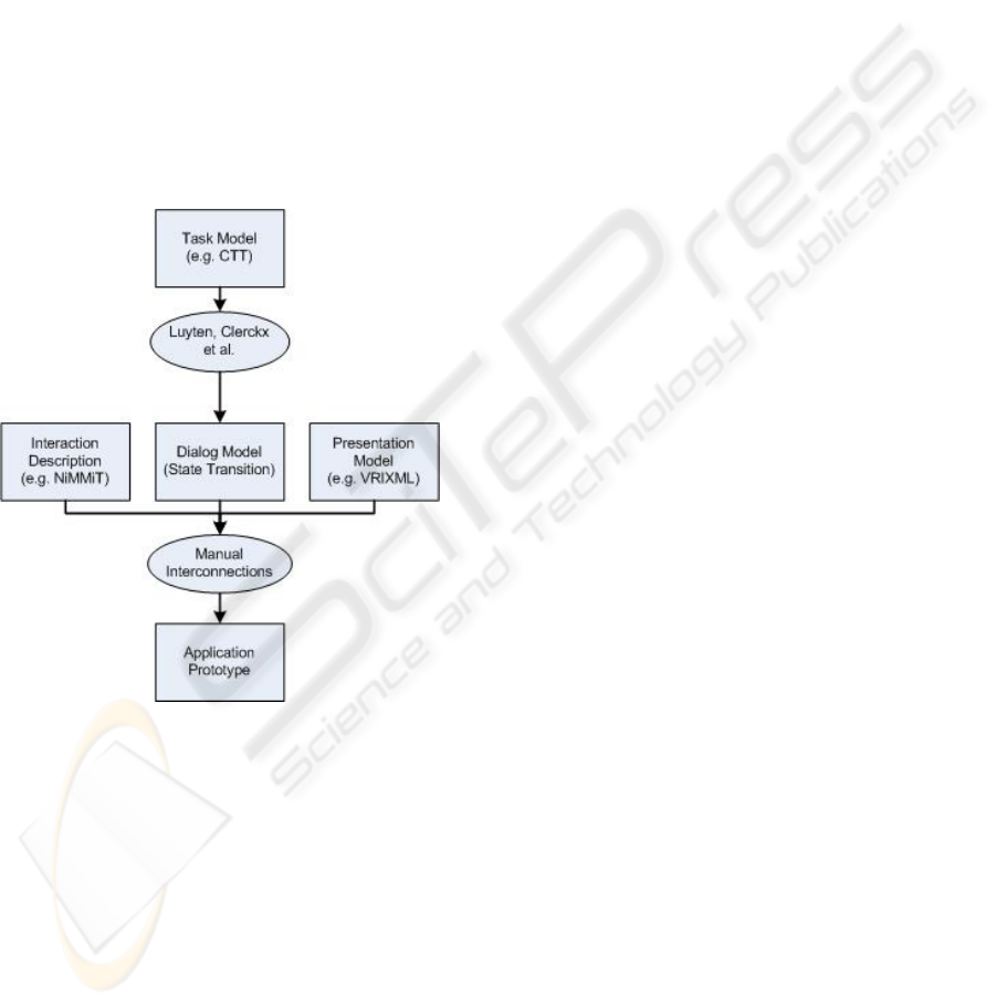
Figure 1: Schematic Overview of the VR-DeMo Process.
The process may start from a task-model, de-
scribing the possible tasks and their mutual relations.
This may contain both tasks performed by the user as
well as by the system. From the task-model, a dialog
model is derived. As will be explained later in this pa-
per, the first step may be optional so that the designer
directly starts by creating a dialog model.
To provide the information for the user interac-
tion, the dialog model is annotated with a presenta-
tion model, describing the UI widgets, and an inter-
action description. The interconnection of the pre-
sentation model and the interaction description with
the dialog model is a manual process, in which the
designer has to indicate which events correspond to a
given task.
After annotating the dialog model, an application
prototype is built that can be executed immediately.
The prototype also contains the application code and
some metadata containing the contents of the mod-
els. If necessary, a programming specialist can tweak
the code. The last step can be considered as an it-
erative process, which means that the interaction de-
scription model, the presentation model, and the final
annotation of the dialog model, can be altered, while
all changes afterwards are preserved.
3 DIALOG MODEL
Although the dialog model forms the center of the
CoGenIVE, the VR-DeMo approach leaves to free-
dom to import a task model. We have chosen not to
include a task model editor into CoGenIVE as good
editors already exist (Mori et al., 2002).
3.1 Defining the States
In CoGenIVE, the dialog model is represented as
a state chart, which can be created manually or by
importing a task model. Each state represents the
tasks that are currently enabled and hence can be
performed. For instance, when the user has chosen
to manipulate a given object (and thus is in a given
‘state’ of the application), he can only move or rotate
an object, and is for instance unable to create a new
object.
The dialog model can be created manually by
dragging the states on the canvas and assigning a
name to them. The tasks that are enabled for a par-
ticular state are assigned as described in section 3.2.
Alternatively, the designer may start by creating a
task model. For this model, we have chosen to use
the ConcurTaskTree (CTT) notation (Patern
`
o, 2000),
as this notation provides the required flexibility and
allows to make use of temporal relationships be-
tween the different tasks. For the creation of a CTT,
we propose to use the ConcurTaskTree environment
(CTTE). CoGenIVE can transform this model into
a dialog model, using the algorithm of Clerckx et
al. (Clerckx et al., 2004a). This transformation groups
all tasks that can be executed at a particular mo-
ment into an Enabled Task Set (ETS) (Patern
`
o, 2000).
These different ETSs correspond to the states in the
dialog model of CoGenIVE.
An example of a dialog model is shown in fig-
ure 2. Each rectangle represents a state, while the ar-
rows represent the state transitions. The assignment
of tasks and events with a state is explained in sec-
tion 3.2.
GRAPP 2008 - International Conference on Computer Graphics Theory and Applications
368
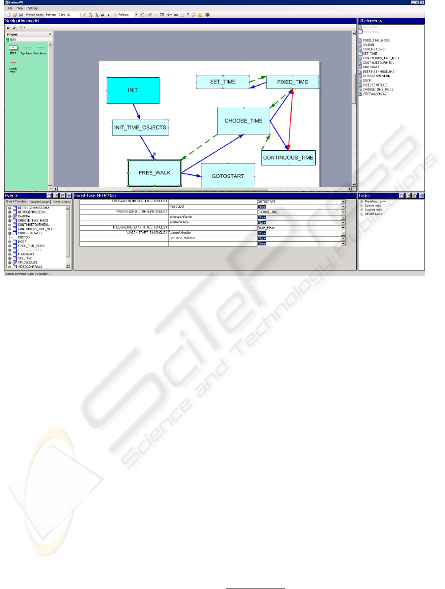
Figure 2: Designing the Dialog Model.
3.2 Handling Input
Interactive Virtual Environments strongly rely on the
user input, which obviously means that we have to de-
fine how the user may interact with the system. The
next step hence is to define the events that will trig-
ger a task in the current state for execution. Events
are generated by event providers, which roughly cor-
respond to the user’s input sources, such as a tracker,
a speech recognition system (defined by a grammar),
a gesture recogniser, or a classic menu or dialog. The
event providers and their possible events are listed
in the bottom left pane called ‘Events’(figure 2), and
their aim is to trigger the tasks in the application.
As a first step in the process, we have to define at
least one input device as event provider, e.g. a tracker.
To add a device, we can choose the type of device
we want to connect, as different devices have differ-
ent properties (number of buttons, force feedback, de-
grees of freedom, . . . ). Based upon the selected de-
vice the relevant events will appear in the tree. Be-
cause we use VRPN (Taylor II et al., 2001) to make
abstraction of the concrete device, the setup can be
changed at will, later on.
The bottom right pane (‘Tasks’), contains a task
list. Tasks may be predefined by the system, they can
be custom-made for the project using a scripting lan-
guage or C++, or they may be an interaction descrip-
tion (as we will explain in section 5). The tasks are
finally associated to a state using the window pane
in the middle between the events and the tasks. By
selecting a state from the dialog model and then drag-
ging an event from the event list, and a task from the
task list into the same line we define that the particu-
lar event triggers the given task (obviously within the
current application state).
Before finishing the dialog model, the designer
may need to define a presentation model or interac-
tion description model, respectively to define user in-
terface elements such as menus, or complex user in-
teraction tasks, as will be explained explained in the
next sections.
4 PRESENTATION MODEL
In many MBUID approaches, the presentation model
describes in an abstract
1
way how the user interface
must look like. From our previous work (Coninx
et al., 1997) (Raymaekers and Coninx, 2001), we have
1
Abstract in this context means that the model does not
take into account features such as the exact placement of a
widget or how it exactly looks like on a given platform.
A TOOL SUPPORTING MODEL BASED USER INTERFACE DESIGN IN 3D VIRTUAL ENVIROMENTS
369
learned that hybrid 2D/3D user interface elements,
such as 2D menus or dialogs, positioned in 3D, are ef-
fective in virtual environments. In order to avoid hav-
ing to hard-code these interaction elements, we have
created VRIXML, an XML-based User Interface De-
scription Language (UIDL), suited for 2D/3D hybrid
menus (Cuppens et al., 2004).
The current version of VRIXML has been ex-
tended in order to realise a cooperation between the
VRIXML presentation model and the interaction de-
scription model. For instance, VRIXML now sup-
ports more events, as well as the possibility to attach
simple scripts to those event. Those scripts are exe-
cuted immediately, without the need to handle them
in the underlying models. This is especially suitable
for simple actions within the dialog, such as the en-
abling or disabling of certain parts.
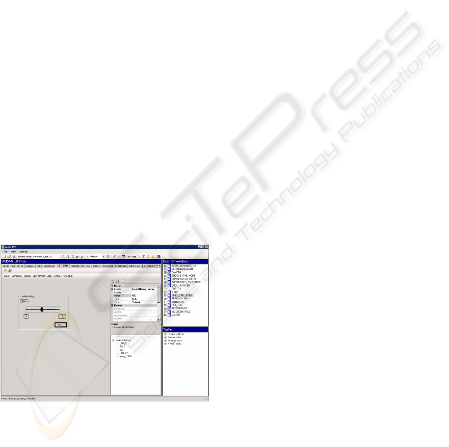
The design of the presentation model is integrated
in CoGenIVE by choosing a user interface (UI) ele-
ment from a list (as can be seen in the top right win-
dow pane of figure 2). The chosen menu or dialog can
then be edited by simple drag-and-drop, and filling
out the requested properties (figure 3). Typically, each
UI element and each item must have a name, defining
the final event that will be fired when activated. The
presentation model in CoGenIVE is designed using a
visualisation which abstracts from the appearance of
the elements in the final VE application. Indeed, de-
pendent on the rendering engine and/or the platform,
menus and dialogs may have a slightly different ap-
pearance.
Figure 3: Designing the Presentation Model.
The presentation model is serialised as a set of
VRIXML files describing the user interface elements
and their events. The events generated by the user in-
terface are added to the event list (fig. 2). The name of
each UI element appears in the top right list (‘UI El-
ements’). Here it can be assigned to an Enabled Task
Set as a default UI element by simply dragging it to
the dialog model.
While our presentation model corresponds to pre-
sentation models in common MBUID approaches,
this is not sufficient to fully describe user interaction
in virtual environments. An enriched interaction de-
scription, as discussed in the next section, overcomes
this lack of expressive power.
5 INTERACTION DESCRIPTION
As most traditional MBUID approaches lack the sup-
port for multimodal interaction, we have developed
NiMMiT, Notation For MultiModal Interaction Tech-
niques. NiMMiT is developed to describe interac-
tion techniques at a much higher level than by writ-
ing code. An interaction technique can be seen a
complex ensemble of multimodal information that is
merged and applied in order to execute a compound
task which consists of several sub-tasks. A good ex-
ample may be ‘touching an object to push it away’.
NiMMiT is a graphical notation, inheriting the for-
malism of a state-chart in order to describe the (mul-
timodal) interaction within the virtual environment.
Furthermore, it also supports dataflow which is im-
portant in the user interaction, as well. A more de-
tailed description of NiMMiTNiMMiT can be found
in (Vanacken et al., 2006) and (Boeck et al., 2007).
We shortly describe the most important primitives of
NiMMiT. An example of a NiMMiT diagram can be
seen in figure 4.
NiMMiT is basically a state chart, in which a state
(represented as a circle) represents the possible events
the user can provide and to which the application lis-
tens. Besides states, NiMMiT contains the following
structures:
• As described in section 3.2, an event is generated
by an action a user can perform, such as moving
a pointing device, speaking a command, clicking
a button, etc. When an event or a combination
of events has been occurred, the particular arrow
points to a task-chain (big rectangles) that is to be
executed.
• A task-chain is a linear succession of tasks that
are executed one after the other.
• A task (smaller rectangle in a task-chain) is set of
actions defined to ‘reach a goal’. A task may be
moving an object or calculating collision between
objects.
NiMMiT also supports data-flow between differ-
ent tasks. Labels (high level variables) are used to
save output from a task (output ports are depicted as
small squares at the bottom right of the task symbol),
GRAPP 2008 - International Conference on Computer Graphics Theory and Applications
370
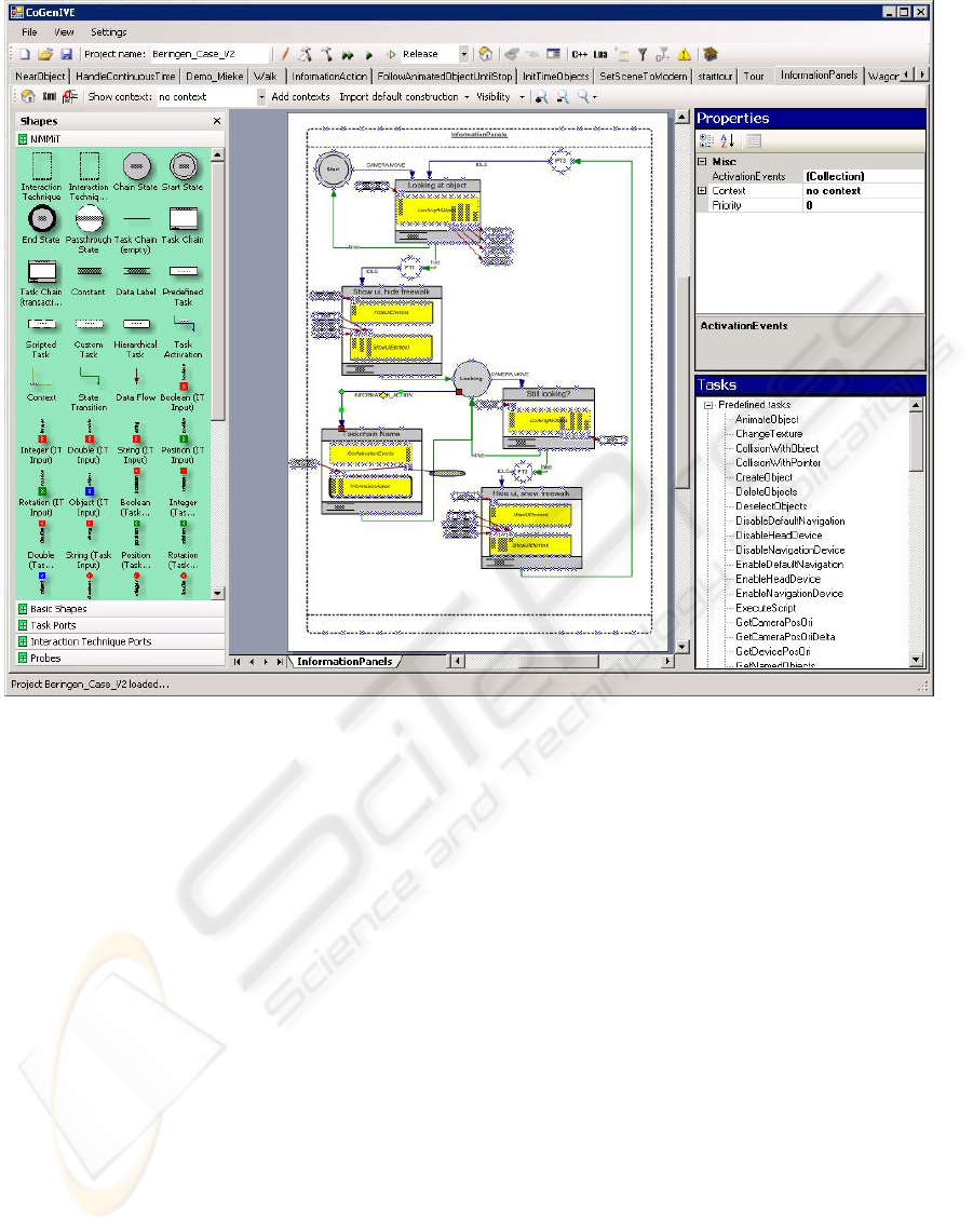
Figure 4: Designing the Interaction Model using the NiMMiT notation.
or to provide input to a task (input ports are depicted
at the top-left of a task)
Tasks are mostly predefined, such as selecting an
object, calculating collision, etc. so that the user can
easily pick them from a list. For specialised actions,
however, custom tasks can be written.
When a task-chain is finished, a state-transition
occurs (light arrow) bringing the interaction into a
new state, responding to another set of events.
In order to support an easy evaluation of
the designed diagrams, NiMMiT also defines
‘probes’,‘filters’ and ‘listeners’(not depicted in fig-
ure 4), primitives that support easy measuring of user
performance and evaluating a proposed interaction
technique (Coninx et al., 2006).
A NiMMiT diagram is created using the NiMMiT
Editor and stored in XML. The XML-file is loaded
by the NiMMiT engine and interpreted and executed
at run-time responding to the relevant events and exe-
cuting the desired tasks.
In order to describe an interaction technique us-
ing NiMMiT (figure 4) the editor allows to (re)use
the events defined by the event providers and UI el-
ements. The tasks in a NiMMiT diagram can be cho-
sen from the tasks list. Moreover, the editor performs
several checks and asserts that NiMMiT diagrams are
correct. For instance, the editor allows that a ‘con-
stant value’ can appear at several places in the dia-
gram while it’s value is automatically kept up to date.
In the same way labels automatically get a data type
dependent on the type of the output port they are con-
nected to, and connections of any type have other vi-
sual representations when they are not properly con-
nected.
6 APPLICATION PROTOTYPE
Finally, when the dialog model is annotated by the
presentation and interaction model and connection
has been made between events and tasks, the appli-
cation can be generated. The application is ready to
be run directly from within CoGenIVE, but as the re-
sult of this step is also a Visual Studio Project file with
the code files (containing the instantiation of all tasks,
devices, and the code of the custom tasks), a program-
A TOOL SUPPORTING MODEL BASED USER INTERFACE DESIGN IN 3D VIRTUAL ENVIROMENTS
371
ming specialist can start tweaking the code within the
designated areas.
It may be stressed here that the final steps in
this process (creating the dialog model, presentation
model, interaction model, and possibly altering the
generated code) may be iterated on, which means that
changes in one model or in the hand-written code may
be preserved in case another model is adapted. This
makes the VR-DeMo approach especially suitable for
creating and evaluating prototypes.
In order to evaluate CoGenIVE, we created some
practical applications, as described in the next section.
These examples illustrate how several prototypes may
be proposed to a customer, in order to search for the
most satisfying solution in a particular case.
7 PRACTICAL USE OF CoGenIVE
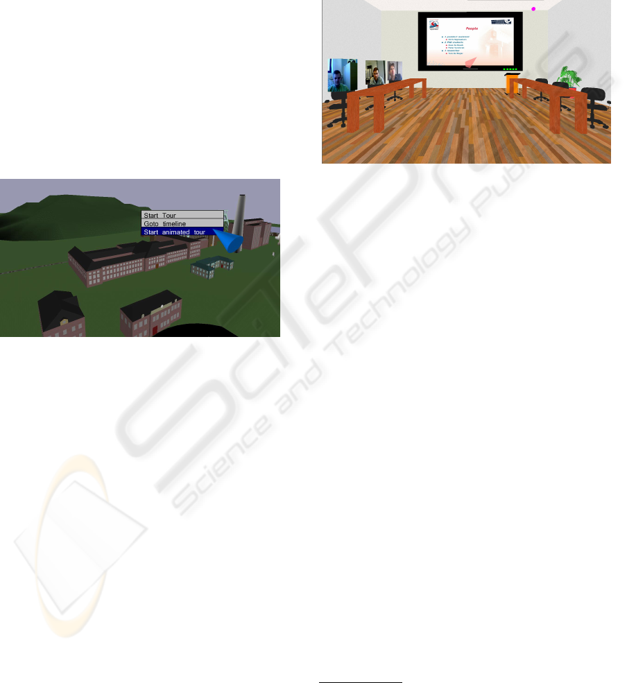
Figure 5: The Virtual Cole Mine Museum.
When designing several case studies, we experienced
CoGenIVE as an helpful tool, stimulating iterative de-
velopment and gradual fine-tuning of the interaction.
A first application created with CoGenIVE, is a
demonstrator for a cole mine museum (fig 5). The
application offers a 3D virtual reproduction of the en-
tire cole mine site, allowing the user to freely explore
the site or follow a guided tour, at which the visitor is
guided, but still can look around, as he or she is mov-
ing their head. Extra information can be requested
upon some interesting buildings or items, and the ap-
plication also contains some animations, illustrating
for instance the coal flow in the mine. The application
also has a feature to show videos at certain places in
the scene, showing movies about the life in the mine,
as well as some QuickTime VR scenes giving a view
on the interior of the buildings.
As the project leader of the coal mine museum
came up with the idea, but did not exactly knew the
possibilities of a IVE in a museum environment, a first
prototype with the features of a first brainstorm was
built. The features included some basic navigation
and extra information menus when approaching cer-
tain objects. In a second iteration we came to the cur-
rent application prototype (including several anima-
tions, QuickTime VR, etc.) which now can be used to
show the possibilities of such an application to the ex-
ecutives. The time spent for the creation of the entire
application, excluding the scene, was about 10 person
days.
Figure 6: The 3D Teleconferencing Application.
A similar approach was applicable for an applica-
tion prototype for a 3D teleconferencing application.
The project leader wanted to explore the possibilities
for a 3D interface supporting teleconferencing. Start-
ing point was to produce an attractive, but easy to
use interface, with some (but not concretely specified)
features such as participants who can start a presenta-
tion. A first prototype has been built and shown to
the project leader. In subsequent iterations, some fea-
tures were added, and others removed. In general this
resulted in an interface in which features could be ac-
tivated with the least amount of clicks possible.
The time required to come to the first version was
about 12 persons days, including the time for the in-
terfacing with the existing teleconferencing library
2
To come to the final prototype, as shown in figure 6,
we required another 4 person days. These time cal-
culations include the modeling of the application, but
exclude the creation of the scene.
The examples above illustrate the possibility of
our tool-supported process to easily create applica-
tion prototypes at a reasonable time. We have also
used CoGenIVE in a context where user interaction
was less important, or at least less of a question. In
the latter application, a 3D driving simulator had to be
created. Although the accent in this project laid on the
simulation aspects, which had to be manually coded,
CoGenIVE played a key role in creating the applica-
tion and designing the overall application structure,
breaking-up the simulation process in several smaller
2
We interfaced with ANDROME’s Intellivic SDK
(www.intellivic.com), writing the interface code as ‘custom
tasks’ in our model based process.
GRAPP 2008 - International Conference on Computer Graphics Theory and Applications
372

building blocks which all could be implemented by
‘custom tasks’, written in C++. In this kind of situa-
tions, the benefit of the tool is not only quickly gener-
ating an initial version. The tools also aids in flexible
extensions while keeping a structured design.
8 RELATED WORK
MBUID has been largely investigated in the context
of standard form-based user interfaces (Vanderdon-
ckt, 2005) Especially the need for a flexible design
in current state of the art user interfaces supporting
multiple devices (Mori et al., 2004), contextual adap-
tations, or distribution and migration of UIs (Clerckx
et al., 2004b) indicate the possibilities of a MBUID
approach. This topic, however, is fairly new in the
domain of interactive virtual environments. In this
section, we will shortly describe how the VR-DeMo
process and CoGenIVE are related to other work.
Although the need for an easier development of
a user interface in a virtual environment is existent,
not so much related research activities can be found.
Some toolkits, such as VR-Juggler (Bierbaum et al.,
2001) offer facilities to a programmer in order to
build a VE application much faster. The applications,
however still have to written in programming code.
Willans et al. (Willans J.S. and S.P., 2000) propose
a methodology that separates the process of design-
ing object behaviour from the process of building a
virtual world. They use existing techniques such as
flownets to describe the behaviour. Similarly, Tan-
riverdi describes how VRID (Virtual Reality Interface
Design) (Tanriverdi and Jacob, 2001) is used to divide
the development process in a high-level and a low-
level phase. The first phase helps designers to con-
ceptually design the interface without implementation
specific terminology. The Low-level phase helps to
represent design specifications in an implementation
oriented terminology. Finally, a commercial tool to
easily develop virtual environments is VirTools (Vir-
tools inc, 2007). It allows a user to define the ob-
ject behaviour and user interaction using a graphical
notation. Although most approaches have their con-
tribution towards the facilitation of the development
cycle, most of them focus directly on programming
issues, rather than on the design and analysis. This
leaves a significant gap and several open issues to ap-
ply MDUID in practice in an IVE (De Boeck et al.,
2006a).
In its general application of form-based user inter-
faces, several popular UIDLs exist that can be used
to describe the presentation model. UIML (User In-
terface Markup Language) (Abrams and Phanouriou,
1999) is a widely used standard. It is an XML-based
meta-language that permits a declarative and device
independent description of a user interface. Because
of its generality, it is possible to use UIML in stead of
languages such as VoiceXML, or WML. But clearly,
UIML’s generality implies that its complexity is a
main drawback. UsiXML (User Interface Extensi-
ble Markup Language) (Vanderdonckt et al., 2004) is
a description language that can be used to describe
a user interface at different levels (going from ab-
stract to concrete user interfaces). UsiXML already
has been applied in a variety of domains, recently in-
cluding VR (Gonzalez et al., 2006). More informa-
tion on how VRIXML relates to other UIMLs can be
found in (Cuppens et al., 2004).
For the description of user interaction, mainly two
families of notations do exist: state-driven notations
and data-driven notations. For the Interaction De-
scription Model, we used NiMMiT, which inherits
the formalisms of a state chart (Harel, 1987), but
adopting some principles of dataflow as well. Popu-
lar State-driven notations are Petri-nets (Palanque and
Bastide, 1994), coloured petri-nets (Jensen, 1994) or
ICO (Navarre et al., 2005). Data driven notations in-
clude InTML (Figueroa et al., 2002) or UML activ-
ity diagrams (Ambler, 2004). For a more comprehen-
sive overview of the related work on this topic, we
refer the interested reader to (Vanacken et al., 2006),
(Boeck et al., 2007) and (De Boeck et al., 2006b).
9 CONCLUSIONS
In this paper we elaborated on a tool ’CoGenIVE’,
supporting the VR-DeMo process, a model based de-
sign process to create VE applications. We showed
how CoGenIVE supports the different steps in the
process, such as creating the dialog model, the pre-
sentation and the interaction model. The approach de-
scribed above facilitates the development of an IVE
in general, but especially creates an environment in
which alternative features within the 3D world can
be easily tried. This has been successfully applied in
some practical cases we described in this paper: the
virtual coal mine museum and the 3D video confer-
ence application. But CoGenIVE has also been ap-
plied in a context where ‘prototyping’ was much less
a requirement, creating a car simulator.
Based upon our experience we can conclude that,
once the VR-DeMo process is known, CoGenIVE of-
fers the designer a useful tool to create VE applica-
tions.
A TOOL SUPPORTING MODEL BASED USER INTERFACE DESIGN IN 3D VIRTUAL ENVIROMENTS
373

ACKNOWLEDGEMENTS
Part of the research at the Expertise Centre for Digi-
tal Media is funded by the ERDF (European Regional
Development Fund), the Flemish Government and
the Flemish Interdisciplinary institute for Broadband
Technology (IBBT). The VR-DeMo project (IWT
030248) is directly funded by the IWT, a Flemish sub-
sidy organization.
The authors also want to thank Erwin Cuppens,
Tom De Weyer, Tim Tutenel and Lode Vanacken for
their valuable contributions to CoGenIVE. We also
want to thank the partners of the VR-DeMo user com-
mittee involved in the practical demonstrator applica-
tions.
REFERENCES
Abrams, M. and Phanouriou, C. (1999). Uiml: An xml lan-
guage for building device-independent user interfaces.
In XML ’99, Philadelphia, USA.
Ambler, S. (2004). Object Primer, The Agile Model-Driven
Development with UML 2.0. Cambridge University
Press.
Bierbaum, A., Just, C., Hartling, P., Meinert, K., Baker, A.,
and Cruz-Neira, C. (2001). VR juggler: A virtual plat-
form for virtual reality application development. In
Proceedings of IEEE Virtual Reality Conference 2001,
Yokohama - Japan.
Bille, W., Pellens, B., Kleinermann, F., and De Troyer, O.
(2004). Intelligent modelling of virtual worlds using
domain ontologies. In Proceedings of the Workshop of
Intelligent Computing (WIC), held in conjunction with
the MICAI 2004 conference, pages 272 – 279, Mexico
City, Mexico.
Boeck, J. D., Vanacken, D., Raymaekers, C., and Con-
inx, K. (2007). High-level modeling of multi-
modal interaction techniques using nimmit. Jour-
nal of Virtual Reality and Broadcasting, 4(2).
urn:nbn:de:0009-6-11615.
Clerckx, T., Luyten, K., and Coninx, K. (2004a). Dynamo-
AID: A design process and a runtime architecture for
dynamic model-based user interface development. In
9th IFIP Working Conf. on Engineering for Human-
Computer Interaction jointly with 11th Int. Workshop
on Design, Speci-fication, and Verification of Interac-
tive Systems EHCI-DSVIS 2004, pages 77–95, Ham-
burg, Germany. Springer-Verlag.
Clerckx, T., Luyten, K., and Coninx, K. (2004b). Dynamo-
AID: a design process and a runtime architecture
for dynamic model-based user interface development.
In Proceedings of EHCI-DSVIS’04, pages 142–160,
Tremsb
¨
uttle Castle, Hamburg, Germany.
Coninx, K., Cuppens, E., De Boeck, J., and Raymaekers,
C. (2006). Integrating support for usability evaluation
into high level interaction descriptions with NiMMiT.
In Proceedings of 13th International Workshop on De-
sign, Specification and Verification of Interactive Sys-
tems (DSVIS’06), volume 4385, Dublin, Ireland.
Coninx, K., Van Reeth, F., and Flerackers, E. (1997). A hy-
brid 2D/3D user interface for immersive object mod-
eling. In Proceedings of Computer Graphics Interna-
tional ’97, pages 47–55, Hasselt and Diepenbeek, BE.
Cuppens, E., Raymaekers, C., and Coninx, K. (2004).
VRIXML: A user interface description language for
virtual environments. In Developing User Interfaces
with XML: Advances on User Interface Description
Languages, pages 111–117, Gallipoli, Italy.
De Boeck, J., Gonzalez Calleros, J. M., Coninx, K., and
Vanderdonckt, J. (2006a). Open issues for the devel-
opment of 3d multimodal applications from an MDE
perspective. In MDDAUI workshop 2006, Genova,
Italy.
De Boeck, J., Raymaekers, C., and Coninx, K. (2006b).
Comparing NiMMiT and data-driven notations for de-
scribing multimodal interaction. In Tamodia 2006,
Diepenbeek, Belgium.
Figueroa, P., Green, M., and Hoover, H. J. (2002). InTml:
A description language for VR applications. In Pro-
ceedings of Web3D’02, pages 53–58, Arizona, USA.
Gonzalez, J., Vanderdonckt, J., and Arteaga, J. (2006). A
Method for Developing 3D User Interfaces of Infor-
mation Systems, chapter 7, pages 85–100. Proc. of
6th Int. Conf. on Computer-Aided Design of User
Interfaces CADUI
´
2006. Springer-Verlag, Bucharest,
Berlin.
Harel, D. (1987). Statecharts: A visual formalism for com-
plex systems. In Science of Computer Programming,
volume 8, pages 321–274.
Jensen, K. (1994). An introduction to the theoretical as-
pects of coloured petri nets. In W.-P. de Roever, G.
Rozenberg (eds.): A Decade of Concurrency, Lecture
Notes in Computer Science, volume 803, pages 230–
272. Springer-Verlag.
Mori, G., Patern
`
o, F., and Santoro, C. (2002). CTTE: sup-
port for developing and analyzing task models for in-
teractive system design. IEEE Transactions on Soft-
ware Engineering, 28(8):797–813.
Mori, G., Patern
`
o, F., and Santoro, C. (2004). Design and
development of multidevice user interfaces through
multiple logical descriptions. IEEE Transactions On
Software Engineering, 30(8):1 – 14.
Navarre, D., Palanque, P., Bastide, R., Schyn, A., Winck-
ler, M., Nedel, L., and Freitas, C. (2005). A formal
description of multimodal interaction techniques for
immersive virtual reality applications. In Proceed-
ings of Tenth IFIP TC13 International Conference on
Human-Computer Interaction, Rome, IT.
Palanque, P. and Bastide, R. (1994). Petri net based design
of user-driven interfaces using the interactive cooper-
ative objects formalism. In Interactive Systems: De-
sign, Specification, and Verification, pages 383–400.
Springer-Verlag.
Patern
`
o, F. (2000). Model-Based Design and Evaluation of
Interactive Applications. Springer-Verlag.
GRAPP 2008 - International Conference on Computer Graphics Theory and Applications
374

Pellens, B., De Troyer, O., Kleinermann, F., and Bille, W.
(2007). Conceptual modeling of behavior in a virtual
environment. Special issue: International Journal of
Product and Development, 4(6):626–645.
Raymaekers, C. and Coninx, K. (2001). Menu interactions
in a desktop haptic environment. In Proceedings of
Eurohaptics 2001, pages 49–53, Birmingham, UK.
Tanriverdi, V. and Jacob, R. (2001). VRID a design model
and methodology for developing virtual reality inter-
faces. In Proceedings of ACM Symposium on Virtual
Reality Software and Technology, Alberta - Canada.
Taylor II, R., Hudson, T., Seeger, A., Weber, H., Juliano, J.,
and Helser., A. (2001). VRPN: A device-independent,
network-transparent vr peripheral system. In In Pro-
ceedings of the ACM, pages 55–61.
Vanacken, D., De Boeck, J., Raymaekers, C., and Coninx,
K. (2006). NiMMiT: A notation for modeling multi-
modal interaction techniques. In Proceedings of the
International Conference on Computer Graphics The-
ory and Applications (GRAPP06), Setbal, Portugal.
Vanderdonckt, J., Limbourg, Q., Michotte, B., Bouillon, L.,
Trevisan, D., and Florins, M. (2004). Usixml: a user
interface description language for specifying multi-
modal user interfaces. In Proceedings of W3C Work-
shop on Multimodal Interaction WMI’2004, pages
35–42, Sophia Antipolis.
Vanderdonckt, J. A. M. (2005). Compliant environment for
developing user interfaces of information systems. In
Proc. of 17th Conf. on Advanced Information Systems
Engineering CAiSE’05, pages 16–31, Porto, Portugal.
Virtools inc (August 2007). Virtools Dev.
http://www.virtools.com.
Willans J.S., H. M. and S.P., S. (2000). Implementing vir-
tual environment object behavior from a specification.
pages 87 – 97.
A TOOL SUPPORTING MODEL BASED USER INTERFACE DESIGN IN 3D VIRTUAL ENVIROMENTS
375
