
AUGMENTING 3D CITY MODELS WITH VISUALIZATION
OF REAL-TIME METEOROLOGICAL PHENOMENA
Frank Steinicke, J
¨
org Mensmann, Klaus Hinrichs, Kai Rothaus
Institute of Computer Science, University of M
¨
unster, Einsteinstr. 62, 48149 M
¨
unster, Germany
Jan de Buhr, Antonio Kr
¨
uger
Institute for Geoinformatics, University of M
¨
unster, Robert-Koch-Str. 26, 48149 M
¨
unster, Germany
K
eywords:
Interactive environments, augmented reality, weather visualization.
Abstract:
General interest in visualizations of digital 3D city models is growing rapidly, and several applications are
already available that display such models very realistically. Many authors have emphasized the importance
of the effects of realistic illumination for computer generated images, and this applies especially to the context
of 3D city visualization. However, current 3D city visualization applications rarely implement techniques for
achieving realistic illumination, in particular the effects caused by current weather-related phenomena. At
most, some geospatial visualization systems render artificial skies—sometimes with a georeferenced determi-
nation of the sun position—to give the user the impression of a real sky. However, such artificial renderings
are not sufficient for real simulation purposes.
In this paper we present techniques to augment visualizations of digital 3D city models with real-time display
of georeferenced meteorological phenomena. For this purpose we retrieve weather information from different
sources, i. e., real-time images from cameras and radar data from web-based weather services, and we use
this information in the rendering process for realistic visualization of different weather-related issues, such as
clouds, rain, fog, etc. Our approach is not limited to a specific setup, and we have evaluated the results in a
user study presented in this paper.
1 INTRODUCTION
Availability of digital 3D city models is on the rise,
and more and more applications for visualizing such
models are forthcoming, ranging from Google Earth
and Microsoft Virtual Earth to academic or indus-
trial visualization systems (Beck, 2003; Dodge et al.,
1998; Steinicke et al., 2006). Although the amount
of data has increased dramatically, these visualiza-
tion and simulation applications can provide very de-
tailed views of a city. Often digital 3D city mod-
els are derived from cadastral maps available as two-
dimensional CAD data sets which include each build-
ing’s footprint as well as the number of floors and
the height between floors. In addition, information
about the infrastructure, street furniture and vegeta-
tion, and also aerial photographs or satellite pictures
may be available. Usually facade images as well
as some highly-detailed 3D models of architecturally
prominent buildings, so-called 3D landmarks, are in-
tegrated. All these features contribute to the realism
of a visualized city model.
Currently, most of the systems for visualization
of urban areas concentrate on displaying the earth’s
surface including the objects located on the surface,
i. e., the terrain with buildings, roads, trees, etc.; for
instance Google Earth displays highly-detailed and
textured terrain models onto which city models are
placed. Although many authors have emphasized the
importance of the effects of realistic illumination for
computer generated images, techniques for achiev-
ing realistic illumination are rarely applied in current
3D city visualization applications. Research is fo-
cussed on improving rendering of the ground surface
instead, e. g., using different caching strategies for
huge amounts of terrain data (Ropinski et al., 2007),
whereas rendering with realistic lighting and the im-
pact on the visualization of the city model is rarely
considered. For instance, when planning a new build-
ing it is important from where and with what inten-
359
Steinicke F., Mensmann J., Hinrichs K., Rothaus K., de Buhr J. and Krüger A. (2008).
AUGMENTING 3D CITY MODELS WITH VISUALIZATION OF REAL-TIME METEOROLOGICAL PHENOMENA.
In Proceedings of the Third International Conference on Computer Graphics Theory and Applications, pages 359-366
DOI: 10.5220/0001098003590366
Copyright
c
SciTePress
sity the sun hits the outer walls and the roof in or-
der to optimize energy consumption. Another exam-
ple is the problem to position a patio or a balcony in
such a way that it has as much sun exposure as pos-
sible. Some approaches have been presented which
consider the effects of light and shadow in city mod-
els, but they are focussed on light interaction between
virtual buildings only, without considering global ef-
fects caused by the virtual sky (D
¨
ollner et al., 2006).
In this paper we present techniques to augment
visualizations of city models with real-time meteo-
rological phenomena. We include information from
real-time video captured with web-based or special-
ized weather cameras, and retrieve current weather in-
formation from web-services, for example, data about
precipitation, cloudiness or fog. Combining all this
information we render a virtual sky having a visual
appearance that comes close to that of the real sky,
and hence the perception of the current weather for a
virtual city model is improved.
The remainder of the paper is structured as fol-
lows. Section 2 examines work related to visualiza-
tion of meteorological phenomena. In Section 3 we
describe our hardware setup and the data acquisition
from different sources about the past, current and up-
coming weather. Furthermore, we explain how to in-
terpret and combine this data. This information is
used by the rendering techniques described in Sec-
tion 4 to generate a realistic sky. Section 5 presents a
user study in which we evaluate how close the visual
appearance of generated virtual skies comes to their
real counterparts. The paper concludes in Section 6.
2 RELATED WORK
Visualizing physical phenomena, e. g., atmospheric
scattering, is one of the main research topics in com-
puter graphics (Schafhitzel et al., 2007). Most of the
early work is based on ray tracing, which is an ap-
propriate method for creating photo-realistic repre-
sentations of the atmosphere. However, due to the
high computational costs, an interactive visualization
was not possible at that time and therefore other ap-
proaches had to be applied. In most systems for visu-
alizing 3D city models the sky is modeled with spher-
ical or cubical shapes surrounding the virtual camera.
Textures showing corresponding images of a sky are
added to the shapes and give the impression of a sky.
When using a sky box, the virtual sky is composed
of six images forming the sides of a cube, i. e., left,
right, top, bottom, front and back textures (see Fig-
ure 1(a)). With such a configuration the appearance
of the virtual sky is limited to an infinite distant sky,
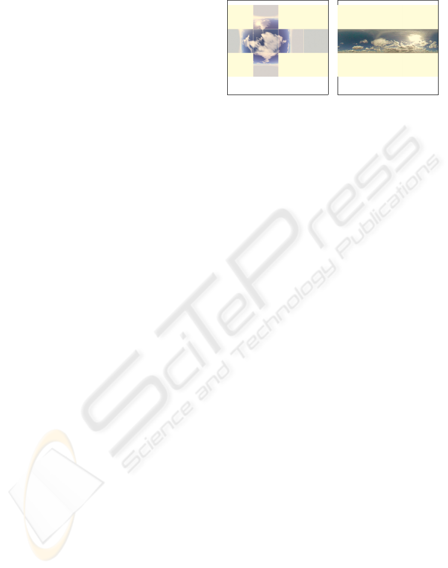
(a) Skybox textures (b) Skydome texture
Figure 1: Texture-based approaches for generating static
virtual skies.
and moreover animations like moving clouds cannot
be integrated easily. Alternatively one can use spheri-
cal domes to which distorted textures are applied (see
Figure 1(b)). Multiple transparent sky domes can vi-
sualize different layers of clouds and stars.
In general, the textures applied to certain sky
geometries already include meteorological informa-
tion, such as color transitions, virtual clouds or a vir-
tual sun. Since static images are used, the visual ap-
pearance is restricted in such a way that changes of
the sky caused, for instance by winds etc., cannot be
incorporated. In order to allow smooth changes in the
visualization of the sky, geodesic domes composed
of uniform patches can be used. A geodesic dome
is an almost spherical structure based on a network
of patches that lie approximately on the surface of a
sphere. Each patch is defined by a certain number of
vertices (at least three), whose color can be changed
in real-time.
Many authors focus on certain properties such as
sunlight or scattering (Riley et al., 2004). Clouds,
for instance, can be modeled as volumetric objects, as
flat images, so-called 3D impostor projected on a sky
dome, or using hybrid approaches (Harris and Las-
tra, 2001; Wang, 2004). Further rendering techniques
for meteorological features have been proposed, such
as using particle systems (Reeves, 1983) for rain ren-
dering (Tatarchuk, 2006) or for visualizing falling
and accumulating snow (Sims, 1990; Fearing, 2000).
Most of these features can be realized using program-
mable shaders in order to allow simple and efficient
rendering on the GPU (Roden and Parberry, 2005).
Some of these aspects have been included in sky ren-
dering libraries, such as SilverLining (Sundog Soft-
ware, 2007) or SkyWorks (Harris, 2004). However,
while these systems provide a good-looking impres-
sion of a virtual sky, they are more targeted on high
rendering performance than on realism. In particular
these applications do not take into account real-time
weather information in order to present an updated
sky.
The information required for rendering such a sky
can be retrieved from different sources. Refined data
GRAPP 2008 - International Conference on Computer Graphics Theory and Applications
360
about general weather conditions is available via sev-
eral web-services. Satellite images comprise cloud
coverage and rainfall, but lack resolution for the rel-
atively small area covered by a city. Stationary cam-
eras that capture the sky provide a more local data
source. The obvious approach to augment the visual-
ization of a 3D city model is to use the resulting video
live streams as background information for the visu-
alization. However, a direct mapping of these images
is not sufficient since they are limited to specific po-
sitions, and usually these cameras cannot record the
entire sky. The latter problem could be diminished
by using all-sky cameras (FMI, 2007) which are used
in astronomy and meteorology for studying aurorae,
meteors and cloud coverage. They are based on fish-
eye lenses or spherical mirrors and can observe the
whole sky at once due to their very wide field of view
(FoV). However, the resulting distortion and their lim-
ited availability makes all-sky cameras unsuitable for
visualization purposes. Another problem with a sta-
tionary camera occurs when the user navigates the vir-
tual camera in such a way that the visible virtual sky
corresponds to a real sky which is out of range of the
stationary camera, and thereupon no data is available
for rendering the sky.
Our goal is to provide a rendered sky with a vi-
sual appearance that comes close to the real sky at the
present time. Furthermore, it should be possible to
visualize weather forecasts as well as weather history.
The virtual skies should be augmented by real-time
information from the acquired camera images as well
as information obtained from other discrete sources
such as weather radars.
3 DATA RETRIEVAL AND
ANALYSIS
In this section we describe the different sources from
where we retrieve the data, in particular current
weather information, in order to generate a virtual city
model and augment it with a realistically looking vir-
tual real-time sky.
3.1 Digital 3D City Model
In cooperation with the urban development, city plan-
ning and transport planning office as well as the
land surveying and land registry office of the city
of M
¨
unster in Germany, we have developed a semi-
automatic process to generate a digital 3D city model
from the cadastral data provided for a city. The cadas-
tral data include for each building its footprint as
well as the number of floors and the height between
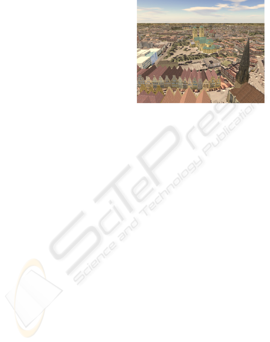
Figure 2: Virtual city model combined with a virtual sky
box showing computer generated static images.
floors, position and type of street furniture, informa-
tion about vegetation, etc. Moreover, the data pro-
vides an elevation model with corresponding aerial
photographs captured during overflights. For the dig-
ital 3D model a solid representing a building is gen-
erated by lifting the polygon describing the building’s
footprint by its total height which is calculated from
its number of floors and the height between floors.
Since a building’s roof type as well as information
about its facades are not included in the cadastral
data we apply heuristics in order to generate a pro-
totypical appearance of these features. In addition
we apply shader-based clipmapping-techniques in or-
der to display the enormous amount of areal images,
which include overall 120 GB of uncompressed data
(Ropinski et al., 2007). This technique enables us
to visualize shadows of clouds on the ground as de-
scribed in Section 4. Since automatically process-
ing virtual buildings as described above lacks most
of the details of their real counterparts particularly
for architecturally prominent buildings like churches.
For this reason we have modeled several of these 3D
landmarks with a very high level-of-detail manually
(Steinicke et al., 2006). The entire model consists
of more than 150,000 buildings, vegetation objects
and street furniture as well as more than 50 landmark
buildings. Besides the concepts described in this pa-
per, the model can also be enhanced with a sky based
on textured virtual skyboxes or virtual domes as de-
scribed in Section 2. But as mentioned above this
procedure is limited to static skies, whereas no cur-
rent meteorological information can be incorporated.
The image shown in Figure 2 illustrates the virtual
city model of the city of M
¨
unster. The sky in this
image is displayed using a virtual sky box with the
textures from Figure 1(a).
AUGMENTING 3D CITY MODELS WITH VISUALIZATION OF REAL-TIME METEOROLOGICAL PHENOMENA
361
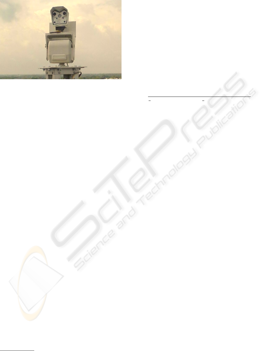
Figure 3: Image of the MOBOTIX HiRes IP camera.
3.2 Steerable Weather-Camera
We have installed a MOBOTIX network camera
(model M12M-Web-D43) on the roof of an eight-
storied building at the coordinates 51
◦
57
58.5
N,
7
◦
36
11.5
E (see Figure 3) (Gliet, 2007). The cam-
era provides a resolution of 1280 × 960 pixels with
a wide angle lens (43 mm, F=2.0). It can be steered
360 degrees horizontally, whereas the vertical pitch is
about 80 degrees. Live stream from the camera and
further information is available via a web-based inter-
face
1
.
Figure 4 shows an image captured with the camera
during the summer in July about noon. Although this
camera provides good images for our approach, the
concepts are not restricted to this specific model. Any
camera or even static images may be used to interpret
the sky and get information as described below. Al-
ternatively we provide a GUI via which the user can
specify the parameters in an arbitrary way.
A trivial approach to generate a virtual sky from
the acquired camera images would be to extract only
the sky and to integrate this video stream into the vir-
tual city model. However, besides image quality prob-
lems due to restricted resolution as well as color falsi-
fication, the limited area which can be captured with
the camera prevents this approach since it results in
insufficient images.
Hence, we choose a different approach. We apply
computer vision strategies in order to extract informa-
tion from images that show parts of the sky. From a
computer vision perspective the given task is to seg-
ment an outdoor image into three main components:
the sky, the clouds and the ground. In fact the latter
is not relevant itself, but is used for the detection of
the horizon and the skyline. We detect the horizon
(see Figure 4) and crop the image such that only the
sky is left. Thereupon we classify the sky pixels as
1
http://ifgicam2.uni-muenster.de
cloud or background. On this clustering result further
parameters for the proposed weather rendering tech-
nique could be deducted. We assume the horizon as
a vertical line and use an extension of the method of
Ettinger et al. (2003) for the detection of the horizon
line. The horizon is an important reference line. With
known internal camera parameters and known global
position of the weather camera, the captured pixels
are embedded in a real world reference system. Et-
tinger et al. classify sky and ground pixel by minimiz-
ing the inner variances of the two RGB-distributions.
We adopt their idea and formulate the optimization
criterion
J =
1
1
4
· min{S(Σ
G
),S(Σ
S
)} +
3
4
· max{S(Σ
G
), S(Σ
S
)}
with the score function S (Σ) := |Σ|+trace (Σ)
2
. Here
Σ
S
and Σ
G
are the class-dependent (sky and ground)
3 × 3 covariance matrices of the red, green and blue
channels. After detecting the horizon line (see Fig-
ure 4(a)), the skyline is extracted by a contour track-
ing method (based on a dynamic programming algo-
rithm) and an objective function similar to the energy
term J. We crop the sky part of the image for further
processing (see Figure 4(b)).
The next step is to classify the sky pixels as clouds
C
cloud
or sky background C
sky
. For this we utilize the
observation that under normal conditions the back-
ground is colored whereas the clouds are rarely col-
ored. The HSI-color model is adequately suited for
such a classifying task, since the S-value represents
the saturation of a pixel p. We use two thresholds t
low
and t
high
for classification and the following rule:
p →
⎧
⎨
⎩
C
cloud
, if S(p) < t
low
C
sky
, if S(p) > t
high
C
both
, otherwise
(1)
The nonspecific class C
both
is introduced due to the
fact that clouds sometimes do not hold a sharp bound-
ary. At the boundary this kind of clouds are trans-
parent and the sky background is visible. Figure
4(c) shows the extracted sky background with origi-
nal color value (H), full saturation (S) and full inten-
sity (I) and the specific clouds in white. The inten-
sity value (I) of the clouds are visible in Figure 4(d).
Here the sky is represented in black. To compute the
percentage of sky cover, we calculate the observed
frequency of cloud pixels in relation to the complete
sky region. The colorization of background can be
estimated by averaging the sky background color de-
pending on the vertical FoV. Furthermore, if individ-
ual clouds can be segmented, i. e., they have a visible
boundary, we copy such clouds into the correspond-
ing textures which are applied during the rendering
GRAPP 2008 - International Conference on Computer Graphics Theory and Applications
362

(a) (b) (c) (d)
Figure 4: The images show the computer vision approach to retrieve information about the current weather: (a) original image
with detected horizon, (b) cropped sky region, (c) pure color of sky pixel with saturation and (d) intensity of cloud pixel with
saturation ≤ t
high
.
process for certain cloud structures (see Section 4).
The entire process can be performed interactively.
3.3 Weather Radar and Web-based
Weather Services
Recognizing certain weather-related features from a
photograph of the sky is limited. For example, solely
by using computer vision algorithms it is often dif-
ficult to distinguish clouds from background such as
in Figure 6. Rain or snow can be distinguished only
when precipitation is extremely high. Currently, we
are working on a more flexible classification method
for cloud and background pixels, which can operate
in more general conditions (dusk, dawn, back light,
halos and so on).
However, due to these limitations we extract fur-
ther weather-related information from weather radar
and web-based weather services. Our cooperation
partner, the working group “climatology” of the Insti-
tute for Landscape Ecology, provides these services to
retrieve data (Institute for Landscape Ecology, M
¨
uns-
ter, 2007) as well as to control and steer sensors, e. g.,
the weather camera. These services provide informa-
tion about minimum and maximum temperature, di-
rection and strength of wind, time of sunrise and sun-
set and percentage of possible sunshine, precipitation
probability and amount of precipitation, atmospheric
humidity, etc. This sensor data is encapsulated by
standardized web services, where three services spec-
ified by the Open Geospatial Consortium (OGC) are
used (Open Geospatial Consortium, 2007):
1. sensor observation services (SOS) which retrieve
meteorological data (e. g. wind direction, wind
speed, temperature),
2. web coverage services (WCS) that retrieve georef-
erenced weather radar data, and
3. sensor planning service (SPS) which enable to
steer the camera.
Data that is obtained from the weather services re-
spectively the weather radar is compared to the inter-
pretation of the camera images. When both differ, for
example, the camera interpretation yields 80% cloud
cover, whereas the weather service prognoses 70%,
we average the results and tune the parameters such
that the visualization of the virtual sky contains 75%
clouds.
4 RENDERING TECHNIQUES
FOR METEOROLOGICAL
PHENOMENA
In this section we explain different rendering tech-
niques that we use for the described meteorological
phenomena.
4.1 Atmospheric Rendering
In our approach atmospheric rendering is based on
a layered model composed of three geodesic domes.
Each geodesic dome is composed of uniformly sepa-
rated patches each having nearly the same size. This
ensures that the sky shading is smooth across the en-
tire dome surface. As depicted in Figure 5 we position
the virtual sun represented by a virtual sphere on the
surface of the outer dome with respect to the georef-
erenced position of the city model as well as the local
time. The size as well as the color is determined by
values derived from the weather web-service. In addi-
tion a distance light is set with respect to the sun’s po-
sition and directed to the center of the 3D city model.
The visualization of the atmosphere is simulated
by multiple intervals with linear color transitions,
defining the color from the horizon to the zenith. The
color values are defined with respect to the color val-
ues determined by the colors from pure color of the
sky images as depicted in Figure 4. Since the cam-
era’s orientation as well as the FoV that records the
image or video stream of the sky is known, corre-
sponding colors are assigned to the vertices of the
geodesic dome (see Figure 5). The vertices which
cannot be assigned to pixels in the camera images are
AUGMENTING 3D CITY MODELS WITH VISUALIZATION OF REAL-TIME METEOROLOGICAL PHENOMENA
363
high clouds dome
middle clouds dome
low clouds dome
example patch
camera position
colored vertex
sun sphere
Figure 5: Arrangement of virtual skydomes supporting
three different layers of clouds.
colored with respect to their distances to already col-
ored vertices while the geodesic dome’s symmetry is
exploited, i. e., vertices which have the same height
are colored in the same way. In addition when ver-
tices are close to the virtual sun even the color of the
virtual sun is merged into the color of the vertex (see
Figure 5). Alternatively, the colors at the horizon and
in the zenith can be defined by the user via a graphi-
cal user interface (GUI). Since the color assignment is
performed in programmable vertex shaders rendering
can be performed in real-time.
4.2 Rendering of Clouds
As described above the three geodesic domes are
composed of almost uniform patches. Consequently,
there is no singular point in which the patches con-
verge, and thus distortion of textures applied to the
surfaces is prevented. Each geodesic dome is associ-
ated to one family of clouds, i. e., high, middle and
low clouds, which are represented as textures on the
corresponding surface. According to (Howard, 1802)
we classify clouds by the altitude of the cloud base.
High clouds form above 5,000 meters in the cold re-
gion of the troposphere; they are denoted as cirrus
or by the prefix cirro-. The clouds tend to be wispy
and are often transparent, e. g., cirrus, cirrostratus,
cirrocumulus, etc. Middle clouds develop between
2,000 and 5,000 meters and are denoted by the prefix
alto-, for example, altostratus and altocumulus. Low
clouds are found up to 2,000 meters and include the
stratus (dense and grey). When stratus clouds con-
tact the ground, they are called fog (see Section 4.3).
Low clouds in this family include, for example, stra-
tus, nimbostratus and stratocumulus.
In order to be able to render clouds at differ-
ent altitudes realistically we render each family of
clouds on the corresponding geodesic’s surface (see
Figure 5). Since the approach is focussed on pedes-
trian navigation where clouds are reasonable far away
from the user’s perspective this approach yields to
sufficient results (Wang, 2004). For each cloud fam-
ily we have generated texture atlases that are com-
posed of different cloud-based textures representing
different cloud types. The textures are encoded in the
RGBA format, i. e., each texel contains an RGB color
entry as well as a transparency value α. Each type of
cloud can automatically be switched on or off and the
amount of each cloud can be controlled as described
in Section 3.2. Alternatively clouds can be controlled
via the GUI by means of controlling the color chan-
nels. For instance, black is associated to no clouds of
the corresponding type, while white is associated to
all clouds represented in the texture. The transparency
of clouds is mapped directly from the α value in the
texture. Furthermore, the color of the clouds can be
changed by means of associating a grayscale value to
each α value. Since we use shaders for each cloud
family, clouds from the same as well as from differ-
ent families can be combined arbitrarily in real-time.
Wind information that we retrieve from the
weather web-service is used to move the clouds in
the corresponding direction by means of rotating each
geodesic dome. The rotation axes are determined by
the cross product of the wind direction and the nor-
mal at the geo-referenced point to the ground model.
Due to the different radii of the three geodesic domes
we ensure that motion parallax caused by clouds is
analog to the real world, i. e., lower clouds appear
to move faster than middle clouds, the latter appear
to move move faster than high clouds. The rotation
speed and axis of each dome is determined by the
wind speed. Furthermore, we use the cloud textures
to apply corresponding shadows on the ground with
respect to the sun position.
4.3 Rendering of Rain and Snow
In our system techniques to render rain and snow are
similar to the rendering of clouds. Different textures
represent different kinds of snow or rain, which are
classified in corresponding categories again. For ex-
ample, according to the amount of precipitation, rain
can range from very light rain, i. e., the precipitation
rate is < 0.25 mm/hour, to moderate rain—when the
precipitation rate is between 1.0 and 4.0 mm/hour,
and to extreme rain, where the precipitation rate is
> 50.0 mm/hour. For each type of rain respectively
snow textures are combined in texture atlases again.
These textures are blended to the inner dome as well
as to the near clipping plane. By means of modifying
the texel position vertically the user gets the notion
of falling rain respectively snow. However, currently
rain and snow have no impact on the visualization of
the ground, e. g., accumulation of fallen snow. Due to
limitations in the computer vision process, we extract
GRAPP 2008 - International Conference on Computer Graphics Theory and Applications
364

information about rain or snow via the weather radar
only.
4.4 Rendering of Fog
The weather web-service gives information about the
visibility range determined by the level of fog. Fog
rendering is implemented in a fragment shader ap-
plied to each fragment, where transparent grayscale
values are blended with respect to its depth value,
i. e., objects which are far away from the camera are
blended with less transparency than objects close to
the camera.
5 SUBJECTIVE EVALUATION
In this section we present an evaluation in which users
had to evaluate how close the visualization of virtual
skies come to their real counterparts.
5.1 Tasks
We have prepared photographs which show a city
from different locations with different weather con-
ditions (see left images in Figure 6). After extract-
ing the corresponding information to define parame-
ters for the rendering process for the virtual sky as
described in Section 3, we have rendered an image
of the virtual 3D city from the same georeferenced
position enhanced with a virtual sky based on our ap-
proaches. We have rendered four more images from
the same position, but have applied a quasi-randomly
(QR) generated sky, i. e., we restricted the visualiza-
tion of that sky such that almost the same weather is
shown, for instance, if the photograph does not show
any clouds, we omitted clouds in the random process.
After comparing each rendered image side-by-
side with the original photo 6 (5 male, 1 female) par-
ticipant students had to state how close the visualiza-
tion of the virtual skies mirror the real ones in terms
of weather-related phenomena. The evaluation had to
be performed on a ten point Likert-scale, where 1 cor-
responds to ”no similarity at all” and 10 corresponds
to ”equality”, i. e., the images show the same weather.
Thereby similarity of the virtual and real weather in
terms of a subjective evaluation is possible, whereas
a comparison based on HDR images would result in
objective evaluation.
5.2 Results
The results of the user evaluation are illustrated in Ta-
ble 1. The table shows the average score of how users
reported the similarity of the sky visualized using our
concepts in contrast to using the QR generated images
with the corresponding photographs.
Table 1: Evaluation of rendered images with respect to pho-
tographs.
Image: Score (φ):
Fig. 6 (a) (right) 7.2
QR image of Fig. 6 (a) (left) 4.6
Fig. 6 (b) (right) 8.2
QR image of Fig. 6 (a) (left) 4.8
Fig. 6 (c) (right) 8.1
QR image of Fig. 6 (a) (left) 5.2
Fig. 6 (d) (right) 8.4
QR image of Fig. 6 (a) (left) 4.45
The results show that users perceive the visualiza-
tion of a virtual sky generated with our approach close
to the real sky, for example, depicted in a photograph.
Overall, users rated our concepts with 7.9 on average,
while a QR image of the same weather has been rated
with 4.76 on average.
6 CONCLUSIONS
We have presented techniques to enhance visualiza-
tions of digital 3D city models with real-time display
of georeferenced meteorological phenomena, such as
the visualization of atmosphere, clouds, sun, rain,
snow and fog. In contrast to other sky rendering li-
braries we have integrated real-time information re-
trieved from different sources, i. e., images from cam-
eras and data from web-based weather services, into
the rendering process in order to achieve a realistic vi-
sualization. The evaluation has proven that skies ren-
dered with our approach come close to the real skies
shown in photographs. Our approach is not limited to
a specific setup, i. e., the weather camera, but is ap-
plicable with any web-based camera as long as parts
of the sky are visible.
In the future we will develop an interface such that
that multiple images from the current sky can be com-
bined to further enhance the visualization of the sky.
Moreover, we will extend the computer vision process
in order to retrieve more information from each im-
age.
REFERENCES
Beck, M. (2003). Real-time visualization of big 3D city
models. International Archives of the Photogramme-
try, Remote Sensing and Spatial Information Sciences,
XXXIV(5/W10).
AUGMENTING 3D CITY MODELS WITH VISUALIZATION OF REAL-TIME METEOROLOGICAL PHENOMENA
365
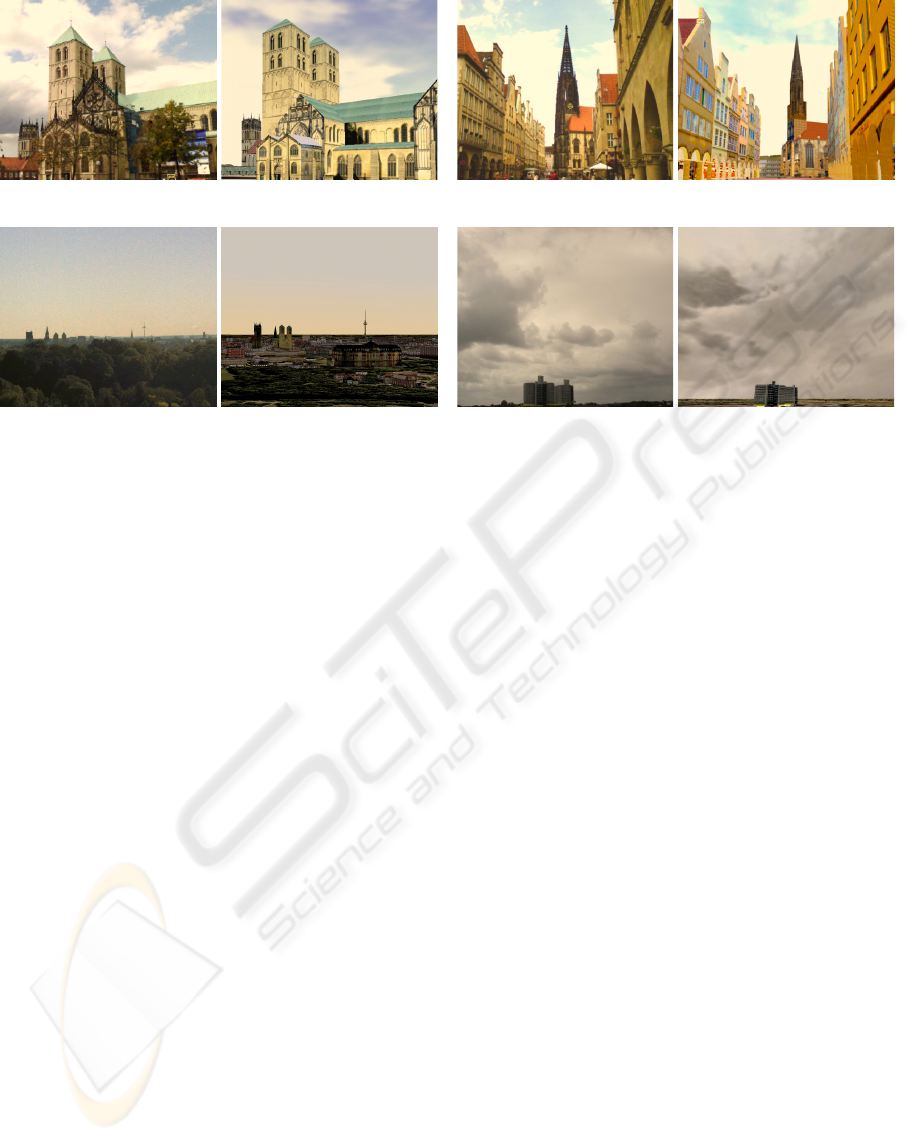
(a) (b)
(c) (d)
Figure 6: Visual comparison between the real respectively virtual sky in photographs respectively rendered images from (a),
(b) pedestrian perspective and from (c), (d) bird’s-eye view.
Dodge, M., Doyle, S., Smith, A., and Fleetwood, S. (1998).
Towards the virtual city: VR & internet GIS for urban
planning. In Workshop on Virtual Reality and Geo-
graphical Information Systems.
D
¨
ollner, J., Buchholz, H., and Lorenz, H. (2006). Ambient
Occlusion - Ein Schritt zur Realistischen Beleuchtung
von 3D-Stadtmodellen. In GIS - Zeitschrift f
¨
ur Geoin-
formatik, pages 7–13.
Fearing, P. (2000). Computer modelling of fallen snow.
In SIGGRAPH ’00: Proceedings of the 27th an-
nual conference on Computer graphics and interac-
tive techniques, pages 37–46. ACM Press/Addison-
Wesley Publishing Co.
FMI (2007). Finnish Metereological Institute all-sky cam-
eras. http://www.ava.fmi.fi/MIRACLE/ASC.
Gliet, J. (2007). Augmented reality weather cam. Master’s
thesis, Institute of Geoinformatics, WWU M
¨
unster.
Harris, M. (2004). SkyWorks cloud rendering engine.
htp://www.markmark.net/SkyWorks.
Harris, M. and Lastra, A. (2001). Real-time cloud render-
ing. Computer Graphics Forum, 20(3).
Howard, L. (1802). The modification of clouds. Presenta-
tion to the Askesian Society.
Institute for Landscape Ecology, M
¨
unster (2007). Cur-
rent weather in M
¨
unster. http://kli.uni-muenster.de/en/
weather.
Open Geospatial Consortium (2007). OpenGIS specifica-
tions. http://www.opengeospatial.org/standards.
Reeves, W. T. (1983). Particle systems – a technique for
modeling a class of fuzzy objects. In SIGGRAPH ’83:
Proceedings of the 10th annual conference on Com-
puter graphics and interactive techniques, pages 359–
375. ACM Press.
Riley, K., Ebert, D., Kraus, M., Tessendorf, J., and Hansen,
C. (2004). Efficient rendering of atmospheric phe-
nomena. In Proceedings of the 15th Eurographics
Workshop on Rendering Techniques, pages 374–386.
Roden, T. and Parberry, I. (2005). Clouds and stars: Ef-
ficient real-time procedural sky rendering using 3D
hardware. In ACE ’05: Proceedings of the 2005
ACM SIGCHI International Conference on Advances
in computer entertainment technology, pages 434–
437. ACM Press.
Ropinski, T., Steinicke, F., Meyer-Spradow, J., and Hin-
richs, K. (2007). Automatic integration of fo-
liage into 3D city models. In International Confer-
ence on Computer Graphics Theory and Applications
(GRAPP2007), pages 299–304.
Schafhitzel, T., Falk, M., and Ertl, T. (2007). Real-time
rendering of planets with atmospheres. In Journal of
WSCG.
Sims, K. (1990). Particle animation and rendering using
data parallel computation. In SIGGRAPH ’90: Pro-
ceedings of the 17th annual conference on Computer
graphics and interactive techniques, pages 405–413.
ACM Press.
Steinicke, F., Ropinski, T., Hinrichs, K., and Mensmann, J.
(2006). Urban city planning in semi-immersive virtual
reality. In Proceedings of the International Confer-
ence on Computer Graphics Theory and Applications
(GRAPP2006), pages 192–199. INSTICC Press.
Sundog Software (2007). SilverLining: 3D cloud and sky
visual simulation. http://www.sundog-soft.com.
Tatarchuk, N. (2006). Artist-directable real-time rain ren-
dering in city environments. In SIGGRAPH ’06: ACM
SIGGRAPH 2006 Courses, pages 23–64. ACM Press.
Wang, N. (2004). Realistic and fast cloud rendering. Jour-
nal of Graphic Tools, 9(3):21–40.
GRAPP 2008 - International Conference on Computer Graphics Theory and Applications
366
