SUGGESTIVE CONTOURS OVER POINT-SET IMPLICITS
Jo˜ao Proenc¸a, Joaquim Jorge
Department of Computer Systems Engineering, INESC-ID/IST/Technical, University of Lisbon, Portugal
Mario Costa Sousa
Department of Computer Science, University of Calgary, Canada
Keywords:
Implicit surfaces, point-based graphics, non-photorealistic rendering.
Abstract:
This paper presents a system that combines large point- set implicit surfaces with fast line-based rendering.
We devised a new process for extracting suggestive contours quickly by using particles scattered throughout
the surface to identify areas of interest, followed by clustering and line- fitting. Furthermore, we improve on
state-of-the-art methods for extracting silhouettes and feature-lines by harness- ing the descriptive power of
the surface representation. This provides heuristics for fast determination of curvature and allows for the local
regeneration of shape-depicting line elements after editing operations. While visual examples illustrate the
high quality of the drawings obtained with our application, as well as the high detail it can provide for more
complex models, run-times show comparatively higher performance over similar approaches for the same
number of points.
1 INTRODUCTION
Non-Photorealistic Rendering (NPR) methods are
commonly used to depict the shape of three-
dimensional objects in a way similar to the exist-
ing types of artistic drawing techniques. Recently,
most of the work presented on real-time extraction
of lines from 3D objects has focused mainly on
polygonal meshes. However, even though meshes
are visualization-friendly structures, they pose serious
difficulties for shape modeling. Namely, memory us-
age increases with both shape size and detail, while it
is difficult to maintain topological consistency with
editing operations. There are other representations
that are better suited for such operations and for which
direct rendering techniques should be devised. One
such representation is the implicit surface, which pro-
vides a simple and flexible mathematical definition
that derives from a potential field function.
In this paper we present techniques to quickly
extract shape-depicting lines from Multi-level Parti-
tion of Unity (MPU) implicits (Ohtake et al., 2003),
which are able to represent complex surfaces from
large sets of points. These techniques were applied
directly to an already existing system (de Araujo and
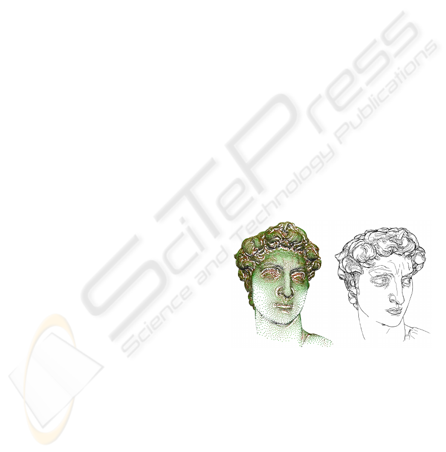
Figure 1: MPU surface computed with a relative error of
5× 10
−4
. Left: David’s Head model with 59994 particles
scattered over the surface. Right: The same model rendered
with our system using silhouettes, suggestive contours and
feature lines.
Jorge, 2004), which allows users to interactively edit
complex objects defined by MPU implicits. The user
is able to apply modeling operations through a cal-
ligraphic interface that converts 2D strokes into 3D
shape modifications. The implementation of our tech-
niques in such a system allowed us to use an already
existing application and is justified by our motivation
to use such rendering methods in an environment that
171
Proença J., Jorge J. and Costa Sousa M. (2008).
SUGGESTIVE CONTOURS OVER POINT-SET IMPLICITS.
In Proceedings of the Third International Conference on Computer Graphics Theory and Applications, pages 171-180
DOI: 10.5220/0001098301710180
Copyright
c
SciTePress

supports shape editing.
Our approach draws inspiration from methods
presented in (Foster et al., 2005) to construct a parti-
cle system over an implicit surface, extract silhouettes
and feature-lines starting from the positions of these
scattered particles and then using surfels to remove
hidden lines. However, their approach does not sup-
port suggestive contours and uses a different implicit
representation (BlobTree), which supports object def-
inition through constructive solid geometry (CSG).
We were more interested in using the MPU since it
allows representing complex models from very large
sets of points, which can be obtained from 3D scan-
ning of real objects. One of the other advantages
of the MPU implicit is its associated octree structure
(Ohtake et al., 2003) that establishes a 3D cell divi-
sion of the surrounding space of the object, in which
the cell subdivision level is higher in areas of higher
complexity. We highlight the main contributions of
our work below.
• We present a novel technique for extracting sug-
gestive contours from implicit surfaces. This is
done by identifying particles that lie in surface ar-
eas where a suggestive contour exists, clustering
those and applying line-fitting algorithms. This
process works even when the local curvature in-
formation is not well-behaved, making our tech-
nique generalizable to most implicit surface rep-
resentations, not just MPUs.
• We use the MPU cell subdivision information as a
heuristic that in many ways improves the perfor-
mance and precision of both the particle system
simulation and the line extraction process. Indeed,
probing the hierarchical level of each cell allows
us to heuristically determine line lengths for con-
tours, which tend to be shorter in areas of higher
detail (deeper cell levels) and longer in flatter re-
gions (cells closer to octree root).
• We provide support for dynamic line-elements, by
using the MPU octree to allow locally regenerat-
ing particles and view-independent lines at inter-
active speeds after shape editing operations, even
in surfaces with tens of thousands of particles.
We also use the MPU octree to set the initial po-
sitions of particles throughout the surface, which pro-
vides an automatic process for choosing the number
of particles that is adequate for each model without
the need for user intervention, contrary to other meth-
ods (Foster et al., 2005) which use random placement
and require manual adjustments as described in detail
in a previous publication (Proena et al., 2007). All
of these elements come together in one system that
combines the expressiveness of line-based rendering
with the descriptive power of the MPU, to visualize
and edit objects defined by very large sets of points.
2 RELATED WORK
Most of the developed NPR methods that include sil-
houette, feature-line or suggestive contour extraction
focus on polygon meshes and have been gaining mo-
mentum steadily over the past few years (Isenberg
et al., 2003; Gooch et al., 1999; Sousa et al., 2003;
DeCarlo et al., 2003; DeCarlo et al., 2004; Judd et al.,
2007). However, while there was some earlier ef-
forts applied to NPR directly over implicit represen-
trations (Bremer and Hughes, 1998; Elber, 1998) only
in more recent years have we seen a return to the sub-
ject (Plantinga and Vegter, 2003; Foster et al., 2005).
Bremer and Hughes (Bremer and Hughes, 1998)
presented methods for rendering lines over implicit
surfaces, which used ray-intersection to determine
points over the surface and numerical integration pro-
cesses to make them approach the silhouettes and fol-
low them. The same type of ray-driven techniques
were used for positioning short interior strokes and
perform hidden-line removal (HLR). More recently,
Foster et al. (Foster et al., 2005) proposed techniques
that combined these methods with some of the ideas
introduced by Elber (Elber, 1998), such as the us-
age of a Witkin-Heckbert particle system (Witkin and
Heckbert, 1994) for scattering points over the sur-
face instead of the more computationally demand-
ing ray-intersection algorithms. Using a variation of
the Shrink-wrap method (van Overveld and Wyvill,
2004), feature-lines are also extracted from particles
through the identification of straddle points over sur-
face faces. An additional HLR method that used sur-
fels was also presented in that paper. In terms of the
Witkin-Heckbert based particle systems, Levet et al.
(Levet et al., 2006) recently presented a technique
that relies on geometry processing for finding near-
optimal initial positions for particles, which improves
the subsequent simulation time, but their approach
requires more complex calculations in this step than
ours. (Jepp et al., 2006) also extended the develop-
ment of the particle system in (Foster et al., 2005) to
create smarticles that use flocking behaviour for fea-
ture searching and line drawing in implicit surfaces.
In terms of suggestive contours, they are a fairly
recent concept that was introduced by DeCarlo et
al. (DeCarlo et al., 2003; DeCarlo et al., 2004).
These two papers cover the mathematical definitions
for suggestive contours on a surface and their extrac-
tion from polygonal meshes. (DeCarlo et al., 2003)
presents the formal definitions and two algorithmic
GRAPP 2008 - International Conference on Computer Graphics Theory and Applications
172
approaches for producing rendered images of 3D ob-
jects (one in object-space and the other in image-
space). In (DeCarlo et al., 2004) the authors ex-
tend the previous system to render suggestive con-
tours in real-time, using line-movement analysis tech-
niques and fast algorithms for polygon elimination in
the line-searching process. These papers set the stan-
dard for suggestive contour rendering over meshes,
but there are not many papers that cover their extrac-
tion from other types of representations. (Burns et al.,
2005) provides techniques for silhouette and sugges-
tive contour extraction from volume data using auxil-
iary level-sets, but their methods seem more suited to
volumetric rather than surface-only data such as ours.
(Schmidt et al., 2006) attempts to draw this type of
lines over implicits, but uses a low-resolution mesh
as an intermediate step for the line-extracting algo-
rithms, which can be a limiting factor for some sce-
narios. It was our goal to avoid using this type of ap-
proach because the process of reconstructing the mesh
in CSG operations is not straightforward over an im-
plicit. To the best of our knowledge no published pa-
pers cover suggestive contour extraction from implic-
its without resorting to a mesh.
Our approach uses the definitions for suggestive
contours presented in (DeCarlo et al., 2003) to iden-
tify particles in the MPU surface, create clusters from
those particles and form contour lines by the appli-
cation of line-fitting algorithms to the clusters. This
method was inspired by the work presented by (Barla
et al., 2005), which applies geometric clustering algo-
rithms to line drawing simplification. However, their
methods are based on the premise that large sets of
lines are already available for simplification, which
is not our case. Furthermore, the technique oper-
ates in image-space, which would make it impossible
to use our surfel-based HLR method for suggestive
contours. Therefore our approach evolved to extract-
ing curves that represent clustered sets of 3D points.
(Gumhold et al., 2001) presented methods for fea-
ture extraction from point clouds, where minimum-
spanning-trees are built over clusters of points and
later trimmed to form the representative lines. Our
main approach to cluster line-fitting adapted this
method to the characteristics of suggestive contours,
but other approaches that fitted smooth curves to sets
of points were also considered detail in Section 5.3.
2.1 The MPU Surface
An implicit surface (Bloomenthal, 1997) is defined
through the potential function f(x) as the set of points
x=(x,y,z) that respect the condition:
f(x) = iso (1)
where iso is a constant value. In our case, where
iso=0, the negative or positive values of f(x) indi-
cate that x is inside or outside of the object volume
respectively. Implicits by their own nature provide
a compact and flexible definition for highly complex
surfaces and make blending operations easy to apply.
The MPU (Ohtake et al., 2003) is one of the vari-
ous of types of implicit surfaces, which stands out for
providing a method for efficient model construction
from a dense set of control points sampled on the sur-
face of complex objects. Its structure is composed
by three elements: an octree of cubic spatial cells
that cover the object; quadratic functions that approx-
imate the local shape in each cell and weight func-
tions that blend the local functions, thus providing
a precision-controllable approximation to a complex
implicit surface efficiently. The construction of an
MPU implicit is guided by the subdivision of the oc-
tree structure, where cells become smaller and more
numerous in areas where the point positions and nor-
mals suggest a higher curvature. We have extended
the model to support interactive shape-editing opera-
tions. The spatial enumeration allows us to mark the
local MPU cells that are involved in an edit operation
and reconstruct the MPU locally from a new set of
control points, which greatly benefits system perfor-
mance (de Araujo and Jorge, 2004).
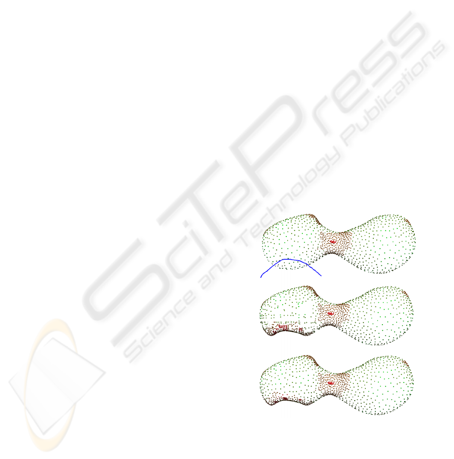
Figure 2: Shape editing. Top: The user defines a CSG cut
over a simple object, using the blue 2D stroke. Center: The
MPU surface is locally altered and new particles are gen-
erated in that area. Bottom: Particles become redistributed
after a local simulation, which takes a few seconds.
SUGGESTIVE CONTOURS OVER POINT-SET IMPLICITS
173

3 OVERVIEW
Our methods follow a high-level approach similar to
Foster et al. (Foster et al., 2005), in which particles are
distributed across the surface. Silhouettes, suggestive
contours and feature lines depicting surface disconti-
nuities are then extracted from the relevant particles.
However, while Foster et al. maintained the parti-
cle system in a constant simulation state (the particle
positions are always being updated in a continuous
cycle), we only let the simulation occur for a maxi-
mum number of iterations that are sufficient for an ac-
ceptable distribution of points throughout the surface.
This results in a limited simulation time, after which
a lot of computational resources are freed for the line-
extracting algorithms. We also provide the users with
the possibility of saving the particle system state to
a file, allowing them to reuse it every time they load
the same object in the application, without having to
endure the simulation process again.
Silhouettes and suggestive contours are view-
dependent elements, so we regenerate them whenever
there is a change in the viewing conditions or when-
ever the particle system is in a simulation state. Fea-
ture lines depicting geometric-dependent discontinu-
ities are view-independent (sometimes they are also
called ridge and valley lines), so we only generate
them once after some iterations of the particle sys-
tem and then apply the appropriate 3D transforma-
tions whenever the viewing conditions change.
Foster et al. treat the implicit representation as a
black-box, i.e. their methods only query the potential
function to extract its value and gradient, making their
approach usable with almost any type of implicit.
While our approach requires the same mathematical
information, we exploit the spatial information pro-
vided by the octree, thus leveraging on the data struc-
tures associated with the MPU. This includes using its
octree for particle and line proximity, instead of using
a regular grid as in their method.
Our system supports modeling operations via a
calligraphic interface (de Araujo and Jorge, 2004).
After an editing operation, we mark the affected oc-
tree cells and start a new particle system simulation
confined to those cells. This makes the regenera-
tion of particles much more efficient, because only
the local particles are affected. This is illustrated in
Figure 2, in which we can clearly see the redistribu-
tion of particles after editing the surface shape. Since
feature-lines are view-independent elements, they are
also locally regenerated. While our work was mainly
concerned with rendering implicit surfaces, it is im-
portant to ensure that shape editing is still possible
and efficient with our techniques, because it is one
of the main motivations for using implicits instead of
other representations, especially in the MPU where
the local reconstruction of surface areas is directly
supported in CSG and blending operations.
Finally, to perform hidden line removal we use a
surfel approach, as in (Foster et al., 2005). Surfels are
oriented ellipses or circles which are used for point-
based rendering of surfaces (Pfister et al., 2000). Our
approach uses circular textures inside quadrilateral
polygons positioned slightly behind each particle us-
ing the surface normal for orientation. These are ren-
dered as white disks and have a radius set by the dis-
tance to the nearest particle. Although this method
does not guarantee a total occlusion for all cases, it is
very effective as long as we have a good distribution
of particles throughout the surface.
4 THE PARTICLE SYSTEM
Our particle system improves on the approach of
Foster et al., which is based on Witkin and Heck-
bert’s (Witkin and Heckbert, 1994) model. While
their methods place particles at random initial posi-
tions, we use the MPU features to obtain a better ini-
tial distribution as described in (Proena et al., 2007),
which we recall here to help in understanding what
folows. Our objective is to achieve denser concentra-
tions of particles in areas of higher surface curvature.
Since octree cells are smaller and more numerous in
those areas, we create k random particles in each cell,
where k is fixed (usually k = 1), and obtain an initial
distribution that is already close to our final objective,
thus saving a considerable number of simulation it-
erations. We obtain a set of n particles, P
i
,i ∈ [1, n],
chosen from the set of MPU control-points that al-
ready lie on the surface. Each of these particles is
registered in the corresponding octree cell, enabling
us to use fast algorithms for point-proximity determi-
nations, using nearby-cell inspection.
The particle system simulation process is com-
posed by a set of iterations where, at each step ev-
ery particle suffers attraction and repulsion forces and
moves accordingly. The calculation of these forces, as
well as the movement of each particle, is performed
in the same way as in (Foster et al., 2005), with the
difference that we compute the repulsion distribution
factor δ
i
in a different way. This value directly influ-
ences the repulsion force and controls the local den-
sity of particles. Foster et al. calculate this using
Hessian values extracted from the potential function
to determine the local mean curvature. This poses a
significant computational burden; we avoid this alto-
gether by using the octree cell depth information on
GRAPP 2008 - International Conference on Computer Graphics Theory and Applications
174
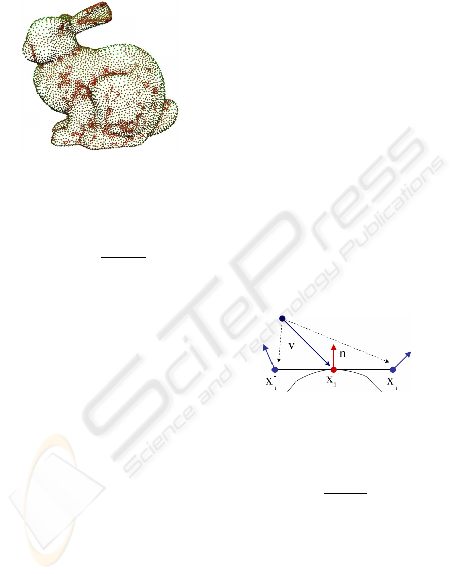
Figure 3: 10000 particles scattered over the surface of the
Bunny model, after running 20 iterations of the particle sys-
tem simulation. Red points correspond to octree cells of
higher depth, green points to lower depth.
the MPU. The depth indicates the cell subdivision de-
gree and therefore is a good heuristic for determining
local curvature, which yields a simpler formula for δ
i
:
δ
i
= weight(
d
i
− d
min
d
max
− d
min
) (2)
where d
i
is the cell depth of particle P
i
and d
max
and d
min
are the maximum and minimum cell depths
where particles exist in the model (these are deter-
mined during the initial particle generation step). The
weight function is a quadratic B-Spline that sets a
higher value for δ
i
if the particle is in one of the lower
depth cells (less curved regions of the surface) and
vice versa. The practical effect of using this technique
is that it is easy and fast to obtain good results where
the particles become well distributed over the surface
to reflect local curvaturewith comparativelyless steps
and a lower cost per particle (see Figures 1 and 3).
5 SUGGESTIVE CONTOURS
Suggestive contours (DeCarlo et al., 2003) are sets
of points that, for a specific camera position, are
seen in a nearby viewpoint (at a radial distance less
than 90 degrees) that are not in correspondence with
silhouette-points of any (radially) closer viewpoint.
What this definition informally means is that if we ob-
serve a suggestive contour in a specific viewing sce-
nario, a silhouette will appear in that same area with
a small change in the viewing position.
The processes described by DeCarlo et al. for sug-
gestive contour extraction in object-space use a defi-
nition that relies on the directional derivativeof the ra-
dial curvature of the surface. This has to be calculated
from principal curvature values extracted from the ob-
ject’s surface, which are usually computed from the
Hessian of the potential function f(x) in an implicit.
It is hard to find implicit representations that yield fast
and numerically stable Hessian values and the MPU
is no exception. It becomes particularly difficult to
obtain these values near discontinuities, where it is
highly probable to find a suggestive contour, because
the potential function of the MPU is not well behaved.
Therefore, our approach relies on another definition
for suggestive contours mentioned by DeCarlo et al.
in their image-space algorithm, namely the set of min-
ima of the dot product between the view vector and
the surface normal in the direction of the projection of
the view vector onto the tangent plane at x. This defi-
nition only requires evaluating gradient values ∇f(x)
from the implicit to obtain the surface normal.
Our suggestive contour extraction process begins
with identifying the particles that lie in suggestive
contour areas. We then form clusters of particles close
to one another and apply line-fitting algorithms to
each cluster to obtain the suggestive contours. In the
next three sections we describe each of these methods
in detail.
5.1 Identifying Suggestive Contour
Particles
Figure 4: The positions x
+
i
and x
−
i
are calculated over the
planar surface defined by n and x
i
, in the direction of v.
The blue normal vectors are computed by consulting the
gradient of the potential function in x
+
i
and x
−
i
.
The normalized view vector v for a specific sur-
face position x and a view position c is defined as:
v =
(x− c)
k (x− c) k
(3)
Consider w as the projection of v onto the surface tan-
gent plane at x with normal n, obtained from the nor-
malized gradient ∇ f(x)/ k ∇f(x) k. Suggestive con-
tours can be defined as the set of minima of (n· v) in
the direction of w (DeCarlo et al., 2003).
Using this definition, we identify if a particle lies
close to a suggestive contour by estimating if (n · v)
experiences a local minimum at its position. Consider
the two points x
+
i
and x
−
i
defined by:
x
+
i
= x
i
+ k
d
w (4)
SUGGESTIVE CONTOURS OVER POINT-SET IMPLICITS
175

x
−
i
= x
i
− k
d
w (5)
where x
i
is the position of the particle P
i
and k
d
is scale-dependent and controls the displacement be-
tween x
+
i
and x
−
i
(for the tested models we usually
use k
d
= 0.5, Figure 4). Also consider that dp
i
, dp
+
i
and dp
−
i
are the (n· v) values (obtained by consulting
the gradient ∇f(x)) at x
i
, x
+
i
and x
−
i
respectively). If
the following inequalities are verified:
dp
i
< dp
+
i
(6)
dp
i
< dp
−
i
(7)
we can conclude that there is a local minimum be-
tween x
+
i
and x
−
i
and, if k
d
is small enough, x
i
is a fair
estimation of that minimum. Additionally we enforce
the stability threshold mentioned in (DeCarlo et al.,
2003), which excludes areas where the view vector is
almost normal to the surface:
θ
sc
< cos
−1
(dp
i
) (8)
where θ
sc
is a user-defined scalar. If the inequalities
(6), (7) and (8) are verified, we consider that P
i
be-
longs to a suggestive contour.
We use the minima of (n · v) to identify sugges-
tive contour points in object-space, instead of the ze-
ros of radial curvature that are used by DeCarlo et
al., since the latter does not seem to work reliably on
MPUs because it is discontinuous over blending func-
tions. This is a new application of this definition for
suggestive contours and it also allows for their extrac-
tion from implicit surfaces without using an auxiliary
structure such as a polygonal mesh.
5.2 Clustering Points
After identifying suggestive contour particles, we
cluster those particles that are close together on the
surface. Our approach then builds a k-nearest neigh-
bor graph of particles for each cluster. We start by tak-
ing one arbitrary particle P and searching for neigh-
bors in 3D space within a fixed radius. This radius
is multiplied by the δ
i
value of the respective octree
cell to confine this search to a more limited space in
areas of high curvature. From those nearby particles
we select the k nearest (we normally use k = 3) and
those become the neighbors of P in the graph. For
each neighbor we repeat the nearby particle search,
skipping particles that have already been inspected.
The cluster graph becomes complete when the search
yields no new neighbors. We create additional clus-
ters by applying this process to other particles that
have not been inspected yet. Because of the dynamic
nature of the search radius, it is possible to have par-
ticles from one cluster finding nearby particles from
another cluster. In this situation we merge the two
clusters.
5.3 Line Fitting
After clustering particles, we finally apply a line fit-
ting algorithm to extract lines that represent each clus-
ter topology. Our approach is inspired by the methods
presented in (Gumhold et al., 2001) and starts by cre-
ating a minimum-spanning-tree (MST) of the cluster
graph, using the optimized Kruskal algorithm. This
process minimizes the geometric distance between
points.
Since the obtained MST can have a large num-
ber of short branches, we must apply a simplifica-
tion process to extract suggestive contour lines. To
achieve this, we have two options. The first is to com-
pute the longest path in the MST and use the cor-
responding edges as the suggestive contour. To find
this path we take an arbitrary particle P and find the
farthest particle P
f
through breadth-first search. We
then find the particle P
′
f
farthest from P
f
. The longest
path becomes the one connecting those two particles.
The second approach is to trim the tree by removing
short branches. To perform this trimming step, we
go through all of the particles in the MST that have
more than two connections to other particles (inter-
section nodes) and analyze each incident branch. If
the branch leads to another intersection node, it re-
mains intact. We removethe branch if it leads to a tree
leaf node and is composed by less than k
trim
(usually
three) particles. In either approach, the extracted lines
undergo a final smoothing step.
6 SILHOUETTES AND FEATURE
LINES
As with the particle system, our silhouette and
feature-line extraction methods are similar to (Fos-
ter et al., 2005) with four notable improvements. In
what follows, we provide enough background to ex-
plain the base techniques and highlight our changes.
To determine silhouettes, we start by identifying par-
ticles P
i
with position x
i
that verify the following in-
equality:
|v
i
· n
i
| < k
c
(9)
where k
c
is controlled by the user (we use k
c
= 0.05
for the majority of the presented models), v
i
is the
view vector and n
i
is the surface normal at x
i
. This
inequality sets off a surface area where particles are
considered to be close to the real silhouette (let’s call
it silhouette area).
From each identified particle we build the silhou-
ette polyline iteratively by a numerical integration
process. We use the predictor/corrector method pre-
GRAPP 2008 - International Conference on Computer Graphics Theory and Applications
176

Figure 5: Extracting suggestive contours. 1: suggestive contour particles. 2: two clusters are identified and MSTs are built.
3: MST trimming approach. 4: MST longest-path approach. 5: using the longest-path approach and smoothing the lines, we
obtain the suggestive contours.
sented by Foster et al., performing two point move-
ments at each iteration. The first follows an estimated
silhouette direction with a fixed step size, while the
second results from two correction vectors computed
to ensure that the line stays close to the silhouette and
on the surface. Our approach uses a dynamic step
size, by multiplying with the δ
i
value of the MPU
octree cell (described in Section 4) where the point
movement is taking place. This provides better pre-
cision to the silhouette polyline in areas of higher
curvature, because the respective line segments be-
come smaller, while improving performance in areas
of lesser curvature, where the segments become larger
(Improvement 1). The process stops if either (1) we
detect that the silhouette is looping or (2) whenever
it reaches the vicinity of another silhouette line or (3)
when the following inequality is not verified:
|v
i
· n
i
| < k
c
· k
e
(10)
This inequality is similar to (9), with the k
e
parame-
ter added, which expands the silhouette area where
the curve may develop. By doing this, we can set
a smaller k
c
value to limit the number of identified
silhouette particles and allow the silhouette building
process to have a wider area of expansion (by using
k
e
= 2 or k
e
= 3). Since it is very common to have
particles that yield the same silhouette line, this tech-
nique improves the overall performance while main-
taining quality and continuity of the extracted curves
(Improvement 2). After all the silhouettes have been
computed, we perform a 2D analysis to chain pairs
of polylines that are within a certain distance of each
other and follow similar orientation.
For feature-line extraction, we identify particles
that lie in the relevant areas of the surface and build
lines from their positions through numerical integra-
tion methods. We begin by discovering pairs of par-
ticles (straddle points) close to each other, which
present a large difference between their surface nor-
mals. Foster et al. performed this step in the particle
system simulation phase, by comparing the normal of
each particle before and after its movement. Formally,
for a certain particle P
i
with initial surface normal n
i
Figure 6: Silhouettes, Feature Lines and Suggestive Con-
tours drawn over the Cow model.
and normal n
′
i
after the movement, we consider the
two respective positions x
i
and x
′
i
to be straddle points
if:
angle(n
i
,n
′
i
) > k
a
(11)
where angle(v
1
,v
2
) returns the angle between two
vectors and k
a
is the threshold angle (we usually use
k
a
= 0.15).
While this method is usually effective and ex-
tracts enough straddle points for a good visual re-
sult, there are situations where it may fail to find
feature-lines due to our optimizations in the parti-
cle system. Indeed, particles which are initially set
with near-optimal densities throughout the surface
(see Section 4) can sometimes lead to a simulation
stage where there will be very small changes in their
positions. While this provides good performance, it
may limit opportunities to identify straddle points.
Therefore, we devised an alternative method to solve
this problem which we apply when the Foster et al.
method fails. It consists in searching for nearby points
within a fixed radius of each particle and comparing
normals to find pairs that verify Inequality (11) (Im-
provement 3).
After identifying straddle points, we move them
along the respective faces separated by the feature,
while trying to maintain a parallel direction to it.
While this is performed, we estimate intermediate
points that lie near the feature, to yield the feature
SUGGESTIVE CONTOURS OVER POINT-SET IMPLICITS
177
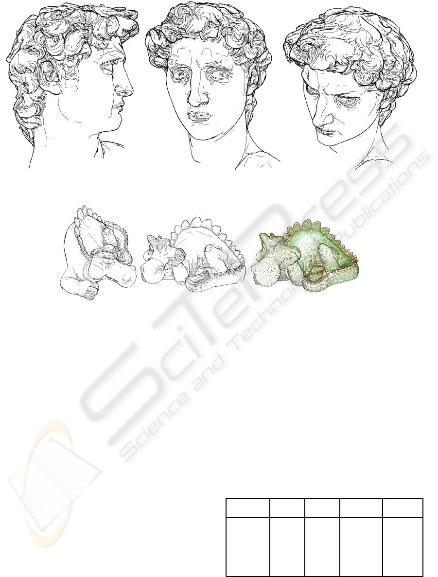
Figure 7: This caption has one line so it is centered.
Figure 8: The Phlegmatic Dragon model rendered using silhouettes, feature-lines and suggestive contours in our system.
polyline. As in the silhouette case, we use the δ
i
value
of the current MPU octree cell to dynamically adjust
the step of the movement to the local curvature (Im-
provement 4). The process stops when Inequality (11)
is not verified or when another feature-line is detected
in the vicinity of the straddle points.
7 RESULTS AND DISCUSSION
Our techniques for extracting silhouettes and feature-
lines proved to be very effective as long as the MPU
surface provides enough shape precision. This usu-
ally depends on the number and density of points in
the object dataset. We are also able to produce sug-
gestive contours for the objects, using our particle
identification and line-fitting techniques.
For the two approaches that we used for fitting
lines onto the suggestive contour MST (Section 5.3),
the longest-path approach is guaranteed to extract sin-
gle continuous line from each cluster, which makes
it usually the best option to avoid artifacts caused
by MST branching. However, when there are sug-
gestive contours that almost intersect, the MST trim-
ming approach is usually able to correctly distinguish
the intersecting lines when the respective clusters are
merged together. This is in fact one of the major dif-
ficulties to overcome in the whole process: there is
always a certain probability that two or more distinct
suggestive contours will be covered by the same par-
ticle cluster because of their proximity. Therefore,
we allow the user to select the appropriate method for
each model.
Table 1: Performance results for our system. Each row in-
dicates the model, number of points in the dataset, number
of points in the particle system, frame-rate with silhouettes
and feature-lines (in frames per second) and frame-rate with
suggestive contours additionally.
Model Dataset Particle w/o Sugg. w/ Sugg.
Points System Contours Contours
Bunny 69451 10000 3.4 1.9
Cow 92864 8334 3.4 1.8
Igea 268686 13665 3.7 1.4
Armadillo 345944 28360 1.6 0.5
Dragon 480076 26984 1.8 0.6
David 827181 59994 0.9 0.2
Table 1 presents the performance results obtained
for the objects depicted in Figures 1, 6, 7, 8 and 9.
GRAPP 2008 - International Conference on Computer Graphics Theory and Applications
178

Figure 9: Renderings using silhouettes, feature-lines and suggestive contours. Left: The Igea model. Center: The Armadillo
model. Right: The Armadillo model showing a particle distribution.
These results were gathered using a 3.6GHz Pentium
IV with 2 gigabytes of RAM and a NVIDIA Quadro
FX 3400 graphics card, running Windows XP SP2.
All of the frame-rates were obtained after the particle
system simulation process had been completed (usu-
ally the simulation comprises 20 iterations).
The number of particles in the particle-system is
always determined by the MPU implicit structure,
since we place one particle per octree cell. This
strategy proved to be very effective for all of the
tested models and also becomes automatic, without
any need for the user to adjust the amount of particles
needed for a correct surface coverage. As the results
suggest, the number of particles is not proportional to
the number of dataset points, because it is also influ-
enced by the surface topology.
The performance results show that it is possible
to achieve interactive frame-rates with medium com-
plexity objects, even while extracting suggestive con-
tours. However, the dimension of the particle system
and the complexity of the model usually affect per-
formance, since they influence the number of implicit
function evaluations that are made and the associated
computational overhead. This also explains why the
suggestivecontour extraction has such an influence on
frame-rate, since it implies a great increase in function
evaluations. Nevertheless, our approach compares fa-
vorably to (Foster et al., 2005) in that, for a similar
frame-rate, we are usually able to render models with
six times the number of particles, while includingsug-
gestive contours which are not handled by their ap-
proach. We should also mention that, while implicit-
based approaches such as ours and the one from Fos-
ter et al. are currently less efficient than mesh-based
ones, it is important to constantly improve these ren-
dering methods because the descriptive flexibility that
an implicit provides is vital in surface modeling and
cannot be obtained when we use a polygonal mesh.
In terms of visual results, we verify that, for higher
point densities in the dataset, the MPU can more ac-
curately represent the surface and the overall line-
extracting process yields better results. This explains
why the David’s Head and Dragon models seem to
present the most impressive depictions (Fig. 7 and 8).
There are however some important remarks to be
made in terms of our system’s limitations. Since
many of our methods are based on Foster et al., we
inherited some of the dependency on parameter set-
ting by the user, namely in terms of adjusting the re-
pulsion between particles and some silhouette extrac-
tion parameters to the scale and topology of the 3D
model. Another limitation is the need for almost com-
plete point clouds to achieve good results. These are
usually obtained from 3D scanning of real objects and
many times only certain portions of the overall sur-
face are scanned. Although our particle system can
deal with occasional holes in the MPU representation,
it cannot effectively distribute points over an incom-
plete surface. Our technique also does not guarantee
that all silhouettes, suggestive contours and feature
lines are extracted from each surface, since the search
for the relevant surface areas, for each viewing posi-
tion, depends on the existence of strategically placed
particles in those areas. This dependencyis evenmore
important for suggestive contours, since they are ob-
tained from particle clusters. This results in unstable
curves that become noticeable as the camera moves.
8 CONCLUSIONS AND FUTURE
WORK
We have presented techniques to extract silhouettes,
suggestive contours and feature-lines directly from
MPU implicits, which are able to represent surfaces
from large sets of points. Our methods benefit from
the spatial information provided by the MPU struc-
ture, enabling us to automatically place particles
throughout the surface and adjust the particle system
and line extracting algorithms to the local shape. This
implicit representation also provides good support for
SUGGESTIVE CONTOURS OVER POINT-SET IMPLICITS
179

shape modifications by allowing us to locally regener-
ate visual elements affected by edits. We improve on
state of the art techniques for line-based rendering of
implicits and introduce a method for suggestive con-
tour extraction from this representation.
Our techniques provide precise and expressive de-
pictions of very complex objects, especially the more
detailed and complete datasets. Our results show bet-
ter performance levels in comparison to similar sys-
tems for the same number of particles. Some areas for
further improvementremain. Among them, new ways
for defining the MPU implicit near the edge areas of
the surface might allow us to draw more precise and
continuous feature-lines. Some work also remains to
be done to improve frame-coherent suggestive con-
tours.
ACKNOWLEDGEMENTS
The models are courtesy of the Digital Michelangelo
Project 3D Model Repository (David’s Head), the
Stanford 3D Scanning Repository (Bunny, Cow and
Armadillo), Cyberware (Igea) and UTIA, Academy
of Sciences of the Czech Republic, and CGG, Czech
Technical University in Prague (Phlegmatic Dragon).
REFERENCES
Barla, P., Thollot, J., and Sillion, F. (2005). Geometric clus-
tering for line drawing simplification. In Proc.of the
Eurographics Symposium on Rendering.
Bloomenthal, J. (1997). Introduction to Implicit Surfaces,
First Edition (The Morgan Kaufmann Series in Com-
puter Graphics). Morgan Kaufmann.
Bremer, D. J. and Hughes, J. F. (1998). Rapid approximate
silhouette rendering of implicit surfaces. In Proc. of
Implicit Surfaces ’98, pages 155–164.
Burns, M., Klawe, J., Rusinkiewicz, S., Finkelstein, A., and
DeCarlo, D. (2005). Line drawings from volume data.
ACM Trans. Graph., 24(3):512–518.
de Araujo, B. R. and Jorge, J. A. P. (2004). Curvature de-
pendent polygonization of implicit surfaces. In Proc.
of SIBGRAPI’04, pages 266–273.
DeCarlo, D., Finkelstein, A., and Rusinkiewicz, S. (2004).
Interactive rendering of suggestive contours with tem-
poral coherence. In NPAR’04, pages 15–24.
DeCarlo, D., Finkelstein, A., Rusinkiewicz, S., and San-
tella, A. (2003). Suggestive contours for convey-
ing shape. ACM Trans. Graph. (Proc. SIGGRAPH),
22(3):848–855.
Elber, G. (1998). Line art illustrations of parametric and im-
plicit forms. IEEE Trans. Vis. Comp. Graph., 4(1):71–
81.
Foster, K., Jepp, P., Wyvill, B., Sousa, M. C., Galbraith, C.,
and Jorge, J. A. (2005). Pen-and-ink for BlobTree im-
plicit models. Computer Graphics Forum, 24(3):267–
276.
Gooch, B., Sloan, P.-P. J., Gooch, A., Shirley, P., and
Riesenfeld, R. (1999). Interactive technical illustra-
tion. In Proc. of the 1999 Symposium on Interactive
3D Graphics, pages 31–38.
Gumhold, S., Wang, X., and MacLeod, R. (2001). Feature
extraction from point clouds. In Proc. of the 10
th
In-
ternational Meshing Roundtable, pages 293–305.
Isenberg, T., Freudenberg, B., Halper, N., Schlechtweg, S.,
and Strothotte, T. (2003). A developer’s guide to sil-
houette algorithms for polygonal models. IEEE Com-
put. Graph. Appl., 23(4):28–37.
Jepp, P., Wyvill, B., and Sousa, M. C. (2006). Smarticles for
sampling and rendering implicit models. Theory and
Practice of Computer Graphics 2006, pages 39–46.
Judd, T., Durand, F., and Adelson, E. H. (2007). Apparent
ridges for line drawing. ACM Trans. Graph., 26(3):19.
Levet, F., Granier, X., and Schlick, C. (2006). Fast sampling
of implicit surfaces by particle systems. In Proc. of
Shape Modeling International, page 39.
Ohtake, Y., Belyaev, A., Alexa, M., Turk, G., and Seidel,
H.-P. (2003). Multi-level partition of unity implicits.
ACM Trans. Graph., 22(3):463–470.
Pfister, H., Zwicker, M., van Baar, J., and Gross, M. (2000).
Surfels: surface elements as rendering primitives. In
Proc. of SIGGRAPH ’00, pages 335–342.
Plantinga, S. and Vegter, G. (2003). Contour generators of
evolving implicit surfaces. In SM ’03: Proc. of the
eighth ACM symposium on Solid modeling and appli-
cations, pages 23–32.
Proena, J., Jorge, J. A. P., and Sousa, M. C. (2007). Sam-
pling point-set implicits. In Eurographics Symposium
on Point-Based Graphics.
Schmidt, R., Isenberg, T., and Wyvill, B. (2006). Interactive
pen-and-ink rendering for implicit surfaces. In ACM
SIGGRAPH 2006 Conference Abstracts and Applica-
tions. ACM Press.
Sousa, M. C., Foster, K., Wyvill, B., and Samavati, F.
(2003). Precise ink drawing of 3D models. Computer
Graphics Forum, 22(3):369–379.
van Overveld, K. and Wyvill, B. (2004). Shrinkwrap: An
efficient adaptive algorithm for triangulating an iso-
surface. The Visual Computer, 20(6):362–379.
Witkin, A. P. and Heckbert, P. S. (1994). Using particles
to sample and control implicit surfaces. In Proc. of
SIGGRAPH ’94, pages 269–277.
GRAPP 2008 - International Conference on Computer Graphics Theory and Applications
180
