
SIMULATION OF CONSTRUCTION PROCESSES WITHIN
VIRTUAL ENVIRONMENTS
Alcínia Zita Sampaio and Pedro Gameiro Henriques
Technical University of Lisbon, Dep. Civil Engineering and Architecture, Av. Rovisco Pais, 1049-001 Lisbon, Portugal
Keywords: Didactic models, Education, Virtual reality, Visual simulation.
Abstract: Three-dimensional geometric models have been used to present architectural and engineering works,
showing their final configuration. But, when the clarification of a detail or the constitution of a construction
step in needed, these models are not appropriate because they do not allow the observation of the
construction activity. Models that could present dynamically changes of the building geometry are a good
support on education in civil engineering domain. Techniques of geometric modelling and virtual reality
were used to obtain interactive models that could visually simulate the construction activity. The
applications explain the construction work of a cavity wall and a bridge. The models present distinct
advantage as educational aids in first-degree courses in Civil Engineering. The use of Virtual Reality
techniques in the development of educational applications brings new perspectives to the teaching of
subjects related to the field of civil construction.
1 INTRODUCTION
Normally, three-dimensional (3D) geometric
models, which are used to present architectural and
engineering works, show only their final form, not
allowing the visual simulation of their physical
increasing. The models concerning construction
needs to be able to produce changes of the geometry
of the project. The integration of geometric
representations of a building together with
scheduling data related to construction planning
information is the bases of 4D (3D + time) models
(Fisher, 2000). In construction field 4D models
combine 3D models with the project timeline (Retik,
1997). In addition Virtual Reality (VR) technology
has been used to turn 4D models more realistic
allowing interaction with the environment
representing the construction place. VTT Building
Technology has been developing and implementing
applications based on this technique improving a
better communication between the partners in a
construction project (Leinonen, 2003).
The use of 4D models just linked with
construction planning software or with
virtual/interactive capacities, concerns essentially
economic and administrative benefits as a way of
presenting the visual simulation of the “real
situation” of the work in several step of its
evolution. Those models are created for each
particular project and are mostly manipulated by the
principal designer or contractor.
Developing didactic models for students
concerns technical tasks, at a level that could be
understood by undergraduate students, but also
pedagogical judgments. In the present study, two
engineering construction work models were created,
from which it was possible to obtain 3D models
corresponding to different states of their shape,
simulating distinct stages in construction processes
(Sampaio, 2006). In order to create models, which
could visually simulate the construction work and
allowing interact with it, techniques of virtual reality
were used. The developed applications make it
possible to show the physical evolution of the work,
the monitoring of the planned construction sequence,
and the visualization of details of the form of every
component of each construction. They also assist the
study of the type and method of operation of the
equipment necessary for these construction
methodologies (Sampaio and Henriques, 2004).
2 DIDACTIC VIRTUAL MODELS
The aim of the practical application of the virtual
models is to provide support in civil engineering
326
Zita Sampaio A. and Gameiro Henriques P. (2008).
SIMULATION OF CONSTRUCTION PROCESSES WITHIN VIRTUAL ENVIRONMENTS.
In Proceedings of the Third International Conference on Computer Graphics Theory and Applications, pages 326-331
DOI: 10.5220/0001099403260331
Copyright
c
SciTePress
education namely in those disciplines relating to
bridges and construction process both in classroom-
based education and in distance learning based on e-
learning technology. Specialist in construction
processes and bridge design were consulted and
involved in the execution of the models in order to
obtain efficient and accurate didactic applications.
The selected examples are two elementary situations
of construction works: an external wall is a basic
component of a building and the cantilever method
of bridge deck construction is applied frequently.
The pedagogic aspect and the technical
knowledge are presented on the selection of the
quantity and type of elements to show in each virtual
model, on the sequence of exhibition to follow, on
the relationship established between the components
of both type of construction, on the degree of
geometric details needed to present and on the
technical information that must go with each
constructive step. Further details complement, in a
positive way, the educational applications bringing
to them more utility and efficiency. Namely, the
model of the wall shows the information concerning
construction activity of interest for students
corresponding to the geometric stage displayed in
each moment and the bridge construction model
shows particularly the movement of the equipment
in operation during the progression.
In addition, the use of techniques of virtual
reality on the development of these didactic
applications is helpful to education improving the
efficiency of the models in the way it allows the
interactivity with the virtual activity. The virtual
model can be manipulated interactively allowing the
teacher or student to monitor the physical evolution
of the work and the construction activities inherent
in its progression. This type of model allows the
participant to interact in an intuitive manner with the
simulated environment, to repeat the sequence or
task until the desired level of proficiency or skill has
been achieved and to perform in a safe environment.
Therefore, this new concept of VR technology
applied to didactic models brings new perspectives
to the teaching of subjects in the area of civil
engineering.
3 3D MODEL OF THE WALL
One of the developed applications corresponds to the
model of a masonry cavity wall, one of the basic
components of a standard construction. To enable
the visual simulation of the construction of the wall,
the geometric model generated is composed of a set
of elements, each representing one component of the
construction. The selection of elements and the
degree of detail of the 3D model configuration of
each component had the support of teachers and
specialist in construction. Using the EON Reality
system (EON, 2003), a system of virtual reality
technologies, specific properties were applied to the
model of the wall in order to obtain a virtual
environment.
3.1 Geometric Modelling of the
Construction Elements
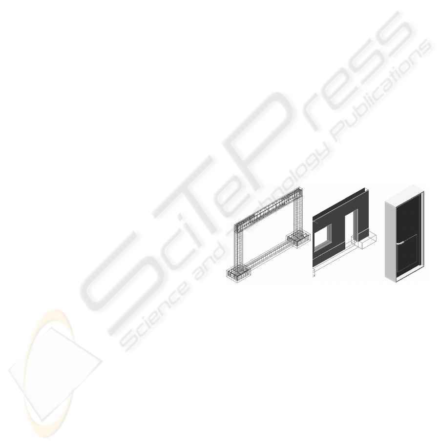
The definition of the 3D model of an exterior wall of
a conventional building comprises the structural
elements (foundations, columns and beams), the
vertical filler panels and two bay elements (door and
window). Every element was modelled using the
AutoCAD system.
The structural elements of the model were
created with parallelepipeds and were connected
according to their usual placement in building
works. Because this is an educational model, the
steel reinforcements were also defined. In the model,
the rods of the reinforcements are shown as tubular
components with circular cross-section (
Figure 1).
Figure 1: 3D models of the wall components.
The type of masonry selected corresponds to an
external wall formed by a double panel of
breezeblocks, 11 cm, wide with an air cavity, 6 cm,
wide (
Figure 1). Complementary to this, the vertical
panels were modelled, comprising: the thermal
isolation plate placed between the brick panels; the
plaster applied to the external surface of the wall; the
stucco applied on the internal surface; two coats of
paint both inside and out and the stone slabs placed
on the exterior surface. Finally, two usual bay
elements, a door and a window, were modelled.
SIMULATION OF CONSTRUCTION PROCESSES WITHIN VIRTUAL ENVIRONMENTS
327
3.2 Programming the Virtual
Construction
The completed model was then transferred to the
virtual reality system EON (as a design file with 3ds
extension). In this system, the visual simulation of
the building process of the wall, following a realistic
plan of the construction progress, was programmed.
For this effect, 23 phases of construction were
considered. The order in which components are
consecutively exhibited and incorporated into the
virtual model, represent realistically the physical
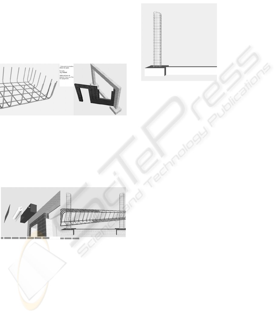
evolution of the wall under construction (Figure 2).
Figure 2: Exhibition of phases in building evolution.
During the animation, the student can control the
length of time that any phase is exhibited and
observe the model using the most suitable camera
and zoom positions for a correct perception of the
details of construction elements. It is possible to
highlight the component incorporated at each
new phase and to examine it in detail (Figure 3).
Figure 3: Elements displaced from the global model of the
wall.
Included, under the window in which the virtual
scene is exhibited, is a bar, which shows the
progress of the construction. Throughout the
animation, the bar is filled, progressively, with small
rectangles symbolizing the percentage built at the
time of the viewing of that particular phase, in
relation to the completed wall construction (Figure
3). Symbolically, it represents the bar diagrams
normally used on construction plans.
Simultaneously, with the visualization of each
phase, a text is shown (in the upper right corner of
the window, Figure 4), giving data relating to the
stage being shown, namely, its position within the
construction sequence, the description of the activity
and the characterization of the material of the
component being incorporated.
Figure 4: Presentation of text describing the exhibited
phase.
The development of the model was supported by
engineer specialist in construction activity. So this is
a guarantee that the model shows the construction
sequence in a correct way and the configuration of
each component was defined with accuracy. In this
educational application, it is important to include
details such as: bar showing the construction
progress; text with information concerning the stage
observed; the possibility to highlight elements from
the model; the accuracy of the reinforcements and
the way then connect inside the structural elements;
the details of the configuration of vertical panels and
components of the window and the door.
4 3D MODEL OF THE BRIDGE
The second model created allows the visual
simulation of the construction of a bridge using the
cantilever method. Students are able to interact with
the model dictating the rhythm of the process, which
allows them to observe details of the advanced
equipment and of the elements of the bridge (pillars,
deck and abutments). The sequence is defined
according to the norms of planning in this type of
work.
The North Viaduct of the Bridge Farm, in
Madeira, Portugal, was the case selected for
representation in the virtual environment (GRID,
1997). In cross-section, the deck of the viaduct
shows a box girder solution and its height varies in a
parabolic way along its three spans. The most
common construction technique for this typology is
the cantilever method of deck construction. This
Phase 5
Cementing the lintel
and foundation
Description:
Cement B30
Dimension of the
foundations:
100x80x40cm3
Dimensions of the
lintel cross section:
25x40cm2
Total volume of
cement:
0.98cm3
GRAPP 2008 - International Conference on Computer Graphics Theory and Applications
328

method starts by applying concrete to a first segment
on each pillar, the segment being long enough to
install on it the work equipment. The construction of
the deck proceeds with the symmetrical execution of
the segments starting from each pillar. The
continuation of the deck, uniting the cantilever
spans, is completed with the positioning of the
closing segment. The support of specialist in bridge
designs was essential to obtain an accurate model,
not only on the geometry definition of components
of the bridge and devices, but also on the
establishment of the progression sequence and of the
way the equipment operates.
4.1 Geometric Modelling of the
Construction Environment
A computer graphic system which enables the
geometric modelling of a bridge deck of box girder
typology was used to generate, 3D models of deck
segments necessary for the visual simulation of the
construction of the bridge. Geometric description
can be entered directly into the deck-modelling
program. To achieve this, the developed interface
presents diagrams linked to parameters of the
dimensions, so facilitating the description of the
geometry established for each concrete case of the
deck. Figure 5 shows the interface corresponding to
the cross-section of the deck of the example.
The description of the longitudinal morphology
of the deck and the geometry of the delineation of
the service road, serving the zone where the bridge
is to be built is carried out in the same way. The
configuration and the spatial positioning of each are
obtained with a high degree of accuracy. Using the
data relating to the generated sections, the system
creates drawings and three-dimensional models of
the deck. To obtain the definition of the deck
segment models, consecutive sections corresponding
to the construction joints are used. The configuration
presented by the segment models is rigorously exact.
Figure 5 shows one of the segments of the deck.
To complete the model of the bridge, the pillars
and abutments were modelled using the AutoCAD
system. Then followed the modelling of the
advanced equipment, which is composed not only of
the form traveller, but also the formwork adaptable
to the size of each segment, the work platforms for
each formwork and the rails along which the
carriages run (Figure 6).
Figure 5: Interface to describe cross-sections and the 3D
model of a deck segment.
Figure 6: 3D models of the scaffolding and the advanced
equipment.
As, along with the abutments, the deck is
concreted with the false work on the ground, the
scaffolding for placement at each end of the deck
was also modelled (Figure 6). Terrain suitable for
the simulation of the positioning of the bridge on its
foundations was also modelled.
4.2 Programming the Construction
Animation
The attribution of virtual properties to the model of
the bridge was implemented by using the virtual
reality system EON Studio (EON, 2003). Once all
the 3D models of the construction environment had
been generated, they were transposed, in 3ds
extension data file format, to the virtual reality
system. The definition of the construction sequence
is based on a counter, which determines the next
action when a mouse button is clicked. The first
action consists of the insertion of the pillars in the
first scenario, which is composed solely of the
landscape. The next step is to place one of the
segments on the top of each pillar. After this, a form
SIMULATION OF CONSTRUCTION PROCESSES WITHIN VIRTUAL ENVIRONMENTS
329
traveller is placed on each segment. The
construction of the deck is defined symmetrically in
relation to each pillar and simultaneously (Figure 7).
For the simulation of the first cantilever segment
(in each span), the four form travellers, the
corresponding work platforms and the formwork
components are included in the scenario. Once the
first segments have been concreted, the construction
of the cantilevered deck takes place. In each phase,
two pairs of segments are defined.
For each new segment the following steps are
established: aising the form traveller; moving the
rails in the same direction as the construction
(relocating them on the latest segment to have been
concreted); moving the form traveller on the rails,
positioning it in the zone of the next segment to be
made; concrete the segment. Finally, the zone of the
deck near the supports is constructed, the false work
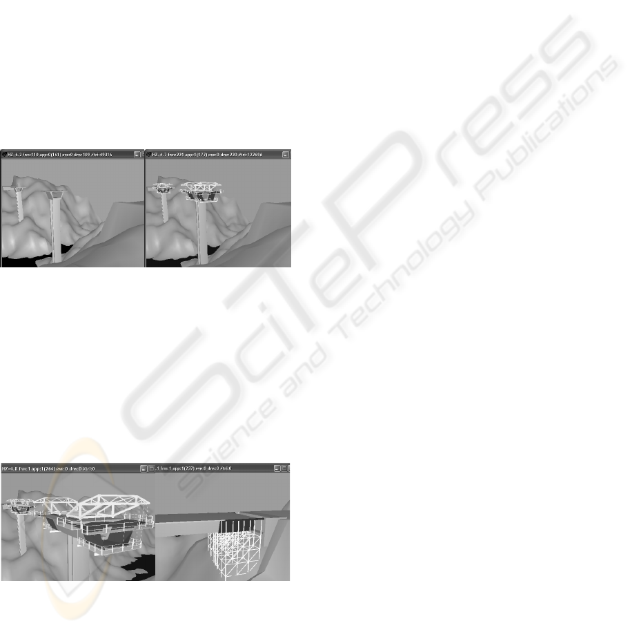
resting on the ground (Figure 8).
Figure 7: Placing the initial pillars and the advanced
equipment.
Moving the camera closer to the model of the
bridge and applying to it routes around the zone of
interest, it is possible to visualize the details of the
form of the components involved in the construction
process. In this way, the student can interact with the
virtual model, following the sequence specifications
and observing the details of the configurations of the
elements involved.
Figure 8: Movement of the advanced equipment and
concreting above the false work near the abutment.
In a real construction place of a bridge, for
security reasons, the student stays far from the local
were bridge is under construction, so they can’t
observe in detail the way of operation and the
progression of the construction. Interacting with the
model of the bridge in class or using their personal
computers they better understand what is going on
there in the construction zone.
5 LEARNING ASPECTS
The models are actually used in face-to-face classes
of disciplines of Civil Engineering curriculum:
Technical Drawing (1
st
year), Construction Process
(4
th
year) and Bridges (5
th
year). The traditional way
to present the curricular subjects involved in those
virtual models are 2D layouts or pictures. Now, the
teacher interacts with the 3D models showing the
sequence construction and the constitution of the
modelled type of work. Essentially, the models are
used to introduce new subjects.
As in Technical Drawing, students have to define
and draw structural plants over the architectural
layouts, the virtual model of the wall helps to
explain the connection between the architectural
drawings and the structural solutions needed to
support the house configuration. Some indication
must be assumed when choosing a structural
solution in order to minimize the unpleasant visual
appearance in the interior of a house when structural
elements (beams, columns, ...) are included in it. The
students are 1
st
year degree, so they have some
difficulty to understand the spatial localization of the
structural elements and how they must be built and
located almost inside the walls. The relationships
between the architectural configurations and the
structural elements in a building are well explained
following the exhibition of the virtual construction
of the wall.
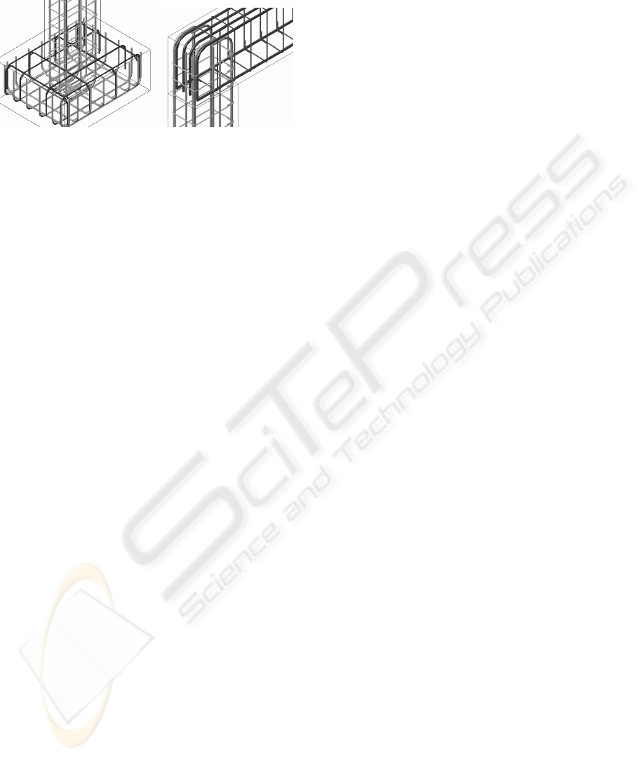
In the discipline of Construction Process, in
order to prepare students to visit real work places,
the teacher shows the construction animation and
explains some aspects of the construction process of
the wall. Namely, the way the net of irons is defined
inside a beam or a column and specially the
complexity of the relationship between the distinct
types of irons near the zone where the structural
elements connect each other (
Figure 9).
In order to clearly explain this issue related to the
structural elements, the iron nets were created as 3D
models with distinct colours, and they appear on the
virtual scenario following a specific planned
schedule. The type, sequence and thickness of each
vertical panel that composes a cavity wall are well
presented in the virtual model showing step by step
the relationship between each other. The
configuration detail of each element of a complete
GRAPP 2008 - International Conference on Computer Graphics Theory and Applications
330
wall can be clearly observed manipulating the virtual
scenario of the construction.
Figure 9: Complex relationship between reinforcements in
the join zones of the structural elements.
The construction model of a bridge particularly
shows the complexity associated to the concrete
work of the deck bridge that is done in a symmetric
way. The model also shows in detail the movement
of the advanced equipment. In class, the professor
must explain way the process must follow that
sequence of steps and the way the equipment
devices operates. When the student, of the 5
th
year,
goes to the work place he can observe the
complexity and the sequence of construction
previously explained.
The students can also interact with those models.
For that, the models were posted on the Internet
pages of undergraduate courses in Civil Engineering.
The student will be able to interact with the
application EonX, which can be accessed at:
http://download.eonreality.com.
6 CONCLUSIONS
It has been demonstrated, through the examples
presented here, how the technology of virtual reality
can be used in the elaboration of teaching material of
educational interest in the area of construction
processes. The pedagogical aspects and the technical
concepts are attended on the elaboration of both
models.
The applications generated represent two
standard situations of constructions. The student can
interact with the virtual model in such a way that he
can set in motion the construction sequence
demanded by actual construction work, observe the
methodology applied, analyze in detail every
component of the work and the equipment needed to
support the construction process and observe how
the different pieces of a construction element mesh
with each other and become incorporated into the
model.
These models are used in disciplines involving
construction in courses in Civil Engineering and
Architecture. They can be used in classroom-based
education and in distance learning supported by e-
learning technology.
REFERENCES
EON, 2003. Introduction to working in EON Studio, EON
Reality, Inc.
Fischer, M., 2000. 4D CAD - 3D Models Incorporated
with Time Schedule, In CIFE in Finland, VTT-
TEKES, Helsinki, Finland.
GRID, 1995. Graphical documentation of the design of
North Viaduct of the Bridge Farm, 1st phase, GRID
Planning office, Lisbon.
Leinonen J., Kähkönen K. and Retik A., 2003. New
construction management practice based on the virtual
reality technology. In 4D CAD and Visualization in
Construction: Developments and Applications, (Ed.)
Raja R.A., Flood I, William J, O’Brien A.A. Balkema
Publishers, pp. 75-100.
Retik A., 1997. Planning and monitoring of construction
projects using virtual reality projects, In Project
Management Journal, 3(97), pp. 28–32.
Sampaio, A. Z., Henriques, P. G. and Studer, P., 2004.
The application of virtual reality technology in
housing projects, In proceedings of the XXXII IAHS
World Congress – Sustainability of the Housing
Projects, Trento (Italy), paper in CDROM (6 pgs),
abstract pp. 26.
Sampaio, A. Z., Henriques, P. G., Studer, P. and Luizi, R.
P., 2006. Learning and planning in virtual scenarios,
In proceedings of the 5th International Conference on
Engineering Computational Technology, ECT 2006,
Las Palmas de Gran Canaria (Spain), paper ECT 113,
abstract pp. 249-250.
SIMULATION OF CONSTRUCTION PROCESSES WITHIN VIRTUAL ENVIRONMENTS
331
