
SPLITTING THE SCENE GRAPH
Using Spatial Relationship Graphs Instead of Scene Graphs in Augmented Reality
Florian Echtler, Manuel Huber, Daniel Pustka, Peter Keitler and Gudrun Klinker
Institut f
¨
ur Informatik I16, Technische Universit
¨
at M
¨
unchen, Boltzmannstr. 3, 85747 Garching, Germany
Keywords:
Scenegraph, spatial relationship graph, augmented reality, tracking.
Abstract:
Scene graphs have been a core element of 3D graphics since the publication of Inventor. However, in Virtual
and Augmented Reality applications, 3D graphics are often interleaved with and controlled by real-world data
provided by pose trackers, cameras and other kinds of sensors. In such a setup, the generalized concept of
a Spatial Relationship Graph (SRG) might be better suited as an underlying data structure to describe the
application and its components. In this paper, we will give an overview of the SRG concept, describe its
difference to a scene graph and provide an example AR application built upon an SRG-based tracking library.
1 INTRODUCTION AND
RELATED WORK
At least since the publication of Inventor (Wernecke,
1994), just about every major graphics system has
been using scene graphs as the underlying data struc-
ture for describing a 3D world. Some widely-known
examples include OpenSG (Reiners, 2002), Open-
SceneGraph (Burns and Osfield, 2004) or Java3D
(Sowizral et al., 1997). One common feature of all
these systems is that they do not use a generalized
graph, but rather a tree or a directed acyclic graph
(DAG).
While this concept has proven highly useful for
rendering large 3D worlds, augmented reality appli-
cations (Azuma, 1995) could benefit from a different
approach. Although scenegraph-based APIs such as
Studierstube (Schmalstieg et al., 2000) or OSGART
(Looser et al., 2006) have been extended in ingenious
ways to enable a wide selection of visualization con-
cepts, we suggest that a variant of the scene graph,
the spatial relationship graph (SRG), is a better-suited
data structure in augmented reality applications.
A classical scene graph contains no representation
for any real-world objects. Consequently, if one or
more transformations in the scene are determined by
external data sources, these transformations change
”out of the blue”, i.e. are influenced by objects not
contained in the scene graph. This leads to a split in
the information necessary to describe the application.
The 3D graphics and their relations are described in
the scene graph, while trackers, cameras etc. are de-
scribed in another, possibly hardcoded, part of the ap-
plication.
The SRG, on the other hand, is a graph which
does not only describe spatial relations between vir-
tual objects, but also between real-world objects such
as cameras or pose trackers that are necessary for AR.
SRGs have been introduced by (Newman et al., 2004;
Wagner, 2005) and further explored by (Pustka et al.,
2006).
A growing trend in many application fields is the
move away from monolithic, compiled code towards
high-level description languages. Such high-level lan-
guages provide, e.g., better maintainability and faster
prototyping. SRGs and the UTQL language (Pustka
et al., 2007) are able to provide such a high-level de-
scription for augmented reality applications by encap-
sulating the scene graph in a wrapper which allows a
unified view of the entire setup.
2 SPATIAL RELATIONSHIP
GRAPHS
An SRG is a directed graph in which nodes represent
coordinate systems. An edge represents a transfor-
mation between the nodes which it connects. This
can, e.g., be a 6D pose for transforming between a
tracker’s world coordinate system and the tracked ob-
ject. It could also be a projective transformation from
3D to 2D coordinates or a 2D feature position in an
456
Echtler F., Huber M., Pustka D., Keitler P. and Klinker G. (2008).
SPLITTING THE SCENE GRAPH - Using Spatial Relationship Graphs Instead of Scene Graphs in Augmented Reality.
In Proceedings of the Third International Conference on Computer Graphics Theory and Applications, pages 456-459
DOI: 10.5220/0001099804560459
Copyright
c
SciTePress

image.
An edge is labeled with attributes. These can be,
e.g., the type of transformation the edge represents
and whether it is a static or dynamic transformation,
i.e. is fixed or changes over time. Usually, the static
transformations are known in advance, for example a
camera calibration.
Ultimately, the goal in most AR applications is to
compute one or more previously unknown transfor-
mations and use these to render an augmentation. The
SRG provides an intuitive way to gather the required
information. Suppose we want to calculate the un-
known transformation from coordinate system A to
system D (see figure 1). The SRG does not contain
a corresponding edge as this transformation is not yet
known. However, if there is a path from A to D, say
via the nodes B and C, that consists of known trans-
formations, then the concatenation of the three trans-
formations A → B, B → C and C → D results in the
previously unknown transformation A → D. Note that
if a transformation A → B is invertible (a 6D pose, for
example), the inverse edge B → A can also be added
to the graph. After inserting this new edge into the
SRG, it can be used in subsequent calculations until
the required transformation has been computed. In
(Pustka et al., 2006), several more complex variants
of such graph relationships, also called spatial rela-
tionship patterns, are described.
Figure 1: Two possible paths from A to D.
3 AUGMENTED REALITY WITH
SRGS
In this section, we present a typical augmented real-
ity application and its representation as an SRG as an
example of how this concept can be used not only for
pure tracking problems, but also for the rendering as-
pect of AR applications. Our setup consists of a cam-
era and several optical markers, each of which is to be
augmented with a different 3D graphics object.
As a consequence, the geometric relationship
between the poses of the virtual objects depends on a
number of independently controllable (tangible) real
objects. The corresponding transformations in the
virtual part of the SRG are not fixed.
The video image from the camera is to be dis-
played in the background. The resulting SRG is pre-
sented in figure 2 and shall be described in this sec-
tion.
The conventions used in this example are as fol-
lows: Static edges are solid, while dynamic edges are
dashed. Each edge is labeled with the type of trans-
formation it represents. Edges which are labeled in
brackets are not yet known and have to be computed
from other edges.
3.1 System and SRG Description
The core of this setup is formed by a real-world cam-
era. This camera introduces two coordinate systems:
first, the 3D camera coordinate system, which usually
has the z-axis pointing along the view direction of the
camera, and second, the 2D image plane coordinate
system. We assume that the transformation between
these two, a projection matrix labeled P
C
in the graph,
is known through a prior camera calibration.
In addition to the camera, an optical flat marker is
present in our setup. Assuming a marker of known
size, four 2D point correspondences are necessary
to calculate the pose of the marker relative to the
camera. These correspondences are themselves trans-
formations between the camera image coordinate
system and the marker coordinate system and are
labeled 2D
4
in the graph. The superscript 4 is used
to denote a multi-edge, consisting of four distinct
transformations.
In order to create a spatially aligned augmen-
tation, we need to take several virtual coordinate
systems into account. In this simple case, there exists
a correspondence between each of the real-world
coordinate systems and a virtual one. These corre-
spondences are labeled with id, denoting the identity
transformation.
Special attention should be paid to the
VirtualOb ject node. Within each such node, a
full scenegraph-based description of graphical detail
can be encapsulated. In figure 2, this is exemplified
by a secondary tree structure inside the node. This en-
capsulating node is equivalent to the root of the scene
graph. While all other scene graph nodes describing
the object could also be integrated into the SRG,
this would likely cause performance problems for
graph algorithms operating on the SRG. Of course,
a more complex AR application is bound to contain
more than one virtual object. In this case, several
encapsulated scene graphs exist and are traversed in
turn when the corresponding object is rendered. If
several identical objects are required, the same scene
graph can even be reused and traversed from different
SPLITTING THE SCENE GRAPH - Using Spatial Relationship Graphs Instead of Scene Graphs in Augmented Reality
457
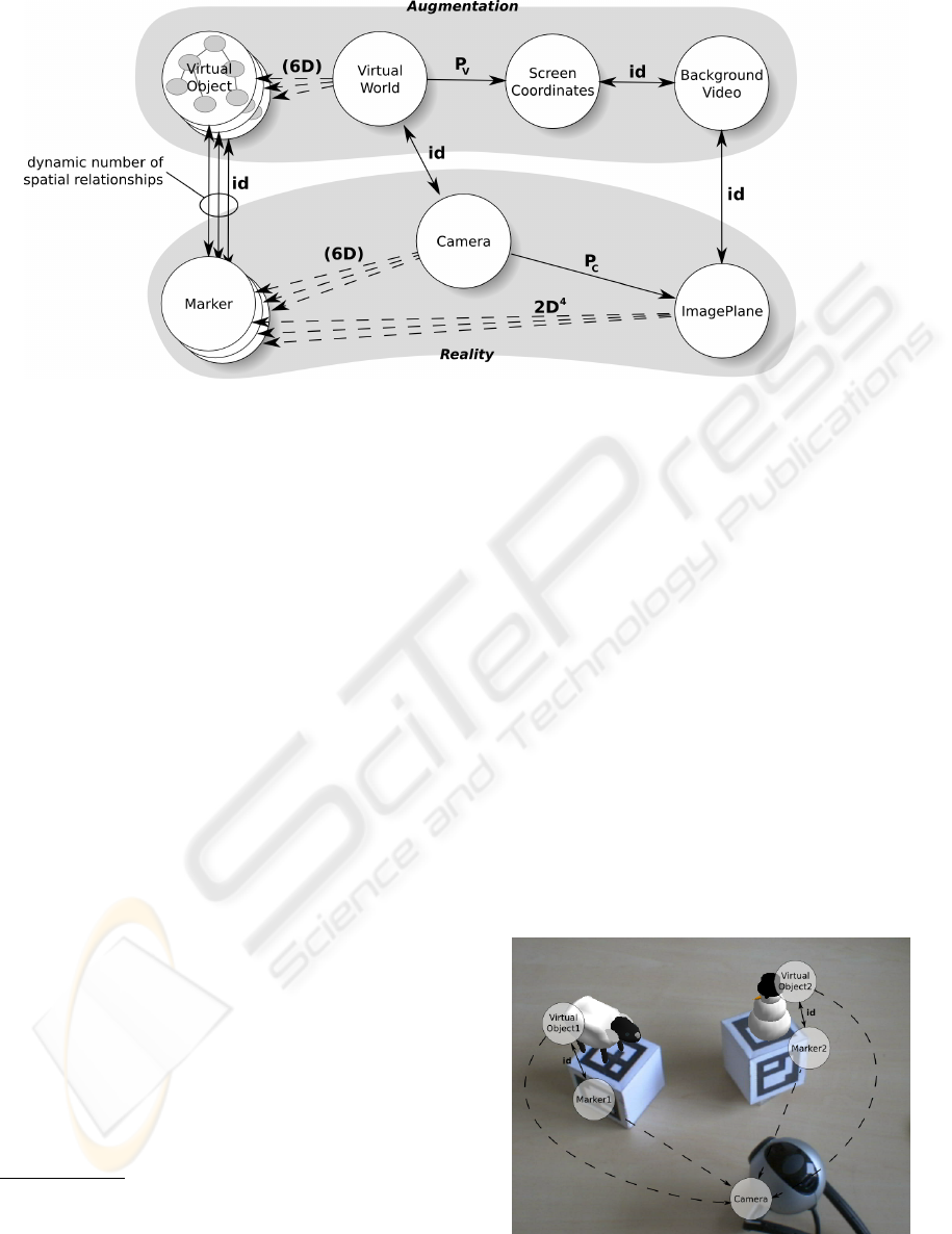
Figure 2: Example SRG for Rendering in AR.
contexts as described, e.g., by (Reitmayr, 2005).
In order to render the object at the correct
position, the transformation labeled (6D) between
the VirtualWorld and VirtualOb ject nodes must be
known. By following the two identity transformations
to the Marker and Camera nodes, we can infer that
these two coordinate systems are linked by the same
transformation. As we assume the camera calibration
P
C
to be known, we can follow the path via the
ImagePlane node and finally calculate the required
6D pose from the aforementioned four 2D-2D corre-
spondences. Note that the Marker coordinate system
is in fact a three-dimensional coordinate system,
as we want to calculate a full 6D transformation to
the Camera system. Therefore, we are dealing with
2D-3D correspondences. However, as the marker is
known to be flat, the third coordinate can be defined
as zero in all cases, reducing the correspondences to
2D-2D.
1
In order to create a credible augmentation, the
video image has to be integrated into our system if no
optical see-through display is available. To achieve
this, we introduce a node BackgroundVideo which is
coplanar with the camera image plane. This node is
also coplanar with the final screen coordinate system
of the resulting image which is to be displayed
to the user. Note that a loop of fixed transforma-
tions exists along the five nodes VirtualWorld,
Camera, ImagePlane, BackgroundVideo and
1
This dimensional reduction could also be represented
in the SRG by introducing an additional 2D coordinate sys-
tem for each marker and a transformation which embeds
this plane into the corresponding 3D Marker system. How-
ever, it was left out in the example SRG to avoid unneces-
sary complexity.
ScreenCoordinates. In order to be consistent with the
previously described constraints, each path between
two of these nodes must result in the same overall
transformation. It therefore follows that the projec-
tion matrix used by the rendering system P
V
has to be
equal to the camera projection matrix P
C
. Otherwise,
the field of view for the augmentation would differ
from the video image, leading to disparities between
the augmented and the real-world view.
3.2 Notes on Implementation
Our example is built on top of the Ubitrack (Huber
et al., 2007) library. As this library’s main focus re-
mains on sensor fusion, we decided against integra-
tion with one of the large scene graph APIs mentioned
above in order to keep the library’s dependency count
low. Instead, we implemented a basic scene graph
Figure 3: Augmented optical markers and corresponding
SRG nodes.
GRAPP 2008 - International Conference on Computer Graphics Theory and Applications
458

traversal based on the XML visitor pattern already
present in the library, taking advantage of the inher-
ent scene graph structure of X3D files. This allows
implementation of a small scene graph API in about
10 kB of C++ code to provide a basic visualization of
encapsulated 3D objects with almost no overhead.
Only if any of the edges incident to the
VirtualWorld node changes, the view has to be re-
rendered. The implementation updates the transfor-
mations to each VirtualOb ject and traverses each en-
capsulated scene graph in turn, thereby avoiding un-
necessary redraws. In our example, which does not
contain interpolators, this results in a synchronization
of the rendered output to the camera frame rate. In fig-
ure 3, our example scenario is shown from a second
camera’s perspective, along with the directly visible
SRG nodes.
4 CONCLUSIONS AND
OUTLOOK
We propose that for augmented reality applications,
the spatial relationship graph is a better-suited data
structure than a scene graph. While the scene graph
is highly useful for pure rendering tasks, the SRG
presents a more intuitive way to incorporate the var-
ious real-world coordinate systems which invariably
are part of AR scenarios. We therefore suggest to split
the scene graph into several static subtrees and encap-
sulate each of those in an SRG node, thereby creating
an unified view of the entire AR application.
ACKNOWLEDGEMENTS
This work was supported in part by a grant from Bay-
erische Forschungsstiftung (BFS) for the TrackFrame
project and in part by the PRESENCCIA project.
REFERENCES
Azuma, R. (1995). A survey of augmented reality. In SIG-
GRAPH ’95 Proceedings (Aug. 1995), pp. 1–38.
Burns, D. and Osfield, R. (2004). Open scene graph - a:
Introduction, b: Examples and applications. In VR
’04: Proceedings of the IEEE Virtual Reality 2004
(VR’04), page 265.
Huber, M., Pustka, D., Keitler, P., Echtler, F., and Klinker,
G. (2007). A System Architecture for Ubiquitous
Tracking Environments. In Proceedings of the 6th In-
ternational Symposium on Mixed and Augmented Re-
ality (ISMAR).
Looser, J., Grasset, R., Seichter, H., and Billinghurst, M.
(2006). OSGART - A Pragmatic Approach to MR. In
Industrial Workshop at ISMAR 2006.
Newman, J., Wagner, M., Bauer, M., MacWilliams, A.; Pin-
taric, T., Beyer, D., Pustka, D., Strasser, F., Schmal-
stieg, D., and Klinker, G. (2-5 Nov. 2004). Ubiquitous
tracking for augmented reality. Mixed and Augmented
Reality, 2004. ISMAR 2004. Third IEEE and ACM In-
ternational Symposium on, pages 192–201.
Pustka, D., Huber, M., Bauer, M., and Klinker, G. (2006).
Spatial Relationship Patterns: Elements of Reusable
Tracking and Calibration Systems. In Proc. IEEE In-
ternational Symposium on Mixed and Augmented Re-
ality (ISMAR’06).
Pustka, D., Huber, M., Echtler, F., and Keitler, P. (2007).
UTQL: The Ubiquitous Tracking Query Language
v1.0. Technical Report TUM-I0718, Institut f
¨
ur In-
formatik, Technische Universit
¨
at M
¨
unchen.
Reiners, D. (2002). Open SG: A Scene Graph System for
Flexible and Efficient Realtime Rendering for Virtual
and Augmented Reality Applications. PhD thesis.
Reitmayr, G.; Schmalstieg, D. (2005). Flexible
parametrization of scene graphs. Virtual Reality, 2005.
Proceedings. VR 2005. IEEE, pages 51–58.
Schmalstieg, D., Fuhrmann, A., Hesina, G., Szalav
´
ari, Z.,
Encarnac¸
˜
ao, L. M., Gervautz, M., and Purgathofer, W.
(2000). The Studierstube Augmented Reality Project.
Technical report, Institute of Computer Graphics and
Algorithms, Vienna University of Technology.
Sowizral, H., Rushforth, K., and Deering, M. (1997). The
Java 3D API Specification.
Wagner, M. (2005). Tracking With Multiple Sensors. PhD
thesis.
Wernecke, J. (1994). The Inventor Mentor: Programming
Object-Oriented 3D Graphics with Open Inventor.
SPLITTING THE SCENE GRAPH - Using Spatial Relationship Graphs Instead of Scene Graphs in Augmented Reality
459
