
EVALUATION OF NEURAL PDF CONTROL STRATEGY
APPLIED TO A NONLINEAR MODEL OF A
PUMPED-STORAGE HYDROELECTRIC POWER STATION
G. A. Munoz-Hernandez, C. A. Gracios-Marin, A. Diaz-Sanchez
Instituto Tecnologico de Puebla, Puebla, México
S. P. Mansoor, D. I. Jones
University of Wales, Bangor, School of Informatics, Dean Street, Bango, LL57 1UT, U.K.
Keywords: Model and Simulation, Power systems, Control applications, Neural control.
Abstract: In this paper, a neural Pseudoderivative control (PDF) is applied to a nonlinear mathematical model of the
Dinorwig pumped - storage hydroelectric power station. The response of the system with this auto-tuning
controller is compared with that of a classic controller, currently implemented on the system. The results
show how the application of PDF control to a hydroelectric pumped-storage station improves the dynamic
response of the power plant, even when multivariable effects are taken into account.
1 INTRODUCTION
Dinorwig is a large pumped storage hydroelectric
scheme located in North Wales that is operated by
the First Hydro Company. The station has six 300
MW rated turbines, driving synchronous generators
which feed power into the national grid. Dinorwig
provides rapid response frequency control when
peak demands occur. This hydroelectric station has a
single tunnel, drawing water from an upper reservoir
into a manifold, which splits the main flow into six
penstocks. Each penstock feeds a turbine to generate
power using a guide vane to regulate the flow. The
electrical power generated is controlled by
individual feedback loops on each unit. The
reference input to the power loop is the grid
frequency deviation from its 50 Hz set point, thus
forming an outer frequency control loop. Mansoor et
al, have derived a multivariable nonlinear simulation
model of this plant, which has provided an improved
understanding of its characteristics (Mansoor, Jones,
Bradley, & Aris, Stability of a pumped storage
hydropower station connected to a power system,
1999) (Mansoor, Jones, Bradley, Aris, & Jones,
2000). Its main features are non-minimum-phase
dynamics, poorly damped poles (associated with
water-hammer in the supply tunnel and electrical
synchronization) and a nonlinear relationship
between flow and power. It is also known (Kundur,
1994) (Working group on prime mover energy
supply, 1992) that there is a significant hydraulic
coupling between the turbines because of the
common supply. This makes the plant a good
candidate for the application of auto-tuning control.
The paper begins with a brief discussion of the
nonlinear mathematical model of the power plant.
Then a few concepts of neural network theory are
reviewed, followed by a description of the
application of neural Pseudoderivative control (PDF)
to the model of Dinorwig (Kang, Lee, Kim, Kwon,
& Choi, 1991). Finally, results are presented which
show the improved response provided by neural
PDF.
259
A. Munoz-Hernandez G., A. Gracios-Marin C., Diaz-Sanchez A., P. Mansoor S. and I. Jones D. (2008).
EVALUATION OF NEURAL PDF CONTROL STRATEGY APPLIED TO A NONLINEAR MODEL OF A PUMPED-STORAGE HYDROELECTRIC POWER
STATION.
In Proceedings of the Fifth International Conference on Informatics in Control, Automation and Robotics - ICSO, pages 259-265
DOI: 10.5220/0001475202590265
Copyright
c
SciTePress

2 HYDROELECTRIC PLANT
MODEL
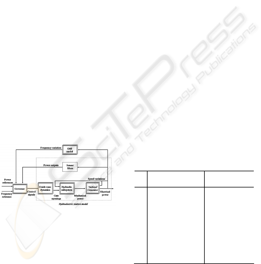
The hydroelectric plant model can be divided into
three subsystems: guide vane, nonlinear hydraulics
and turbine/generator (figure 1). Mansoor et al
developed a multivariable non-linear model that
includes a rate limit and saturation in the guide vane
dynamics, as shown in figure 2 (Mansoor, Jones,
Bradley, Aris, & Jones, 2000).
Guide vane 1
demand angle
Guide vane 2
demand angle
Guide vane 1
Guide vane 2
Electric
subsystem 1
Electric
subsystem 2
Guide vane 1
angle
Guide vane 2
angle
Hydraulic
subsystem
Turbine speed 2
Turbine speed 1
Power 1
Power 2
Filtered
feedback
signal 1
Filtered
feedback
signal 2
P mech 1
P mech 2
Figure 1: MIMO model of the hydroelectric plant with two
penstocks.
Guide vane
angle
1
0.4s+1
1
0.19s+1
Saturation Rate limiter
Guide vane
demand
angle
Figure 2: Guide vane subsystem.
In this study a nonlinear model that takes into
account the effects of the water column, including
water compressibility and pipe wall elasticity, was
employed (Working group on prime mover energy
supply, 1992). Figure 3 shows the nonlinear elastic
model of a single penstock. The coupling effect
between the units is included in the model (main
tunnel block).
Sqrt
Turbine speed
0.5
e
-2T
e
s
2
Z
o
f
p
A
t
Other Penstocks Other Penstocks
q
nl
Main Tunnel
+
-
+
-
+
-
+
+
-
-
(no-load flow)
Head loss coefficient
Surge
impedance
square
X
X
X
ΔG
ΔP
m
Figure 3: Hydraulic subsystem.
The turbine gain value of A
t
depends directly on the
turbine MW rating and inversely on the Generator
MVA rating. f
p
is the head loss coefficient for the
penstock. Z
0
is the surge impedance of the conduit.
T
e
is the wave travel time; it is defined as the time
taken for the pressure wave to travel the length of
the penstock (l) to the open surface. v is the velocity
of sound in water.
v
l
T
e
=
(1)
e
W
T
T
Z =
0
(2)
T
w
is the water starting time of the main tunnel and
the penstocks. Kundur defines the water starting
time as the time required for a head to accelerate the
water in the penstock from standstill to a specific
velocity (Kundur, 1994). Its value depends directly
on the constructional dimensions of main tunnel and
penstocks.
In this model G is the per unit gate opening, P mech
is the mechanical power produced by a single
turbine. The value of T
e
depends on the length of the
penstock and inversely on the wave velocity
(equation 1). Z
o
depends directly on the flow rate,
inversely on the head of water and on the
acceleration due to gravity (equation 2). The value
of A
t
depends directly on the turbine MW rating and
inversely on the Generator MVA rating (Mansoor,
2000). The models are expressed in the per-unit
system, normalized to 300 MW and 50 Hz. The
electrical subsystem is based on the ‘swing’
equations (Kundur, 1994) and includes the effect of
synchronizing torque. For noise reduction a first
order filter is included in the feedback loop (fig. 4).
Turbine speed
Filtered
feedback
signal
Power
0.7071
Synchronizing torque
314.1592
s
integrator
8.38
damping coefficient
1
7.99s
Turbine/generator
1
s+1
Power transducer
P mech
Figure 4: Electrical subsystem.
3 NEURAL NETWORKS
3.1 Basic Theory
Since the early 1980s, there has been a dramatic
increase in research on the computational properties
of highly interconnected networks of simple
processing units called artificial neural networks.
These networks are loosely patterned after the
structure of biological nervous systems. However,
the use of these artificial neural networks (NN) to
improve the behavior of several real systems in
engineering applications has recently been
increased. One of the engineering disciplines that
have been enriched with the properties of the NN is
the adaptive control theory, because they offer the
ICINCO 2008 - International Conference on Informatics in Control, Automation and Robotics
260

possibility to adjust the parameters of the regulator
in order to reduce the difference between the set-
point and the output of the process.
There are several types of NN can be found in
literature (Narendra & Mukhopadhyay, 1996) but in
adaptive control, back propagation is used most
frequently, because its calculation speed is fast and
easy to implement. A back - propagation artificial
neural network is a linear combination of nodes
interconnected to form several layers of nodes that
may or may not have interactions between them,
figure 5.
X1
X2
X3
X4
Wij
Vij
j
h1
k
i
O1
O2
Ok
Om
Figure 5: Generic structure for three layer neural network.
The number of layers used in the network plays an
important factor during the design stage. Two layers
NN have its own limitation but it has a good
performance (Minsky & Papert, 1988). Multilayer
NN have a wide spectrum of applications and they
can deal with problems that are “impossible” to NN
with two layers. As was discussed by Rumelhart et
al (Rumelhart, McClelland, & group, 1986), the
addition of internal layers will allow the back
propagation algorithm to develop an internal
representation of system dynamics; that feature
could be crucial to find a solution. Linear models as
the ARX result on internal models of two layers NN
with back-propagation.
3.2 Neural PDF
One of the main reasons for using NN in control
system is the ability to adjust any non-linear system.
A prior knowledge about the structure of the system
being controlled is very important to tune and
improve the performance of PDF controller.
There are several approaches to define a fast and
efficient control strategy to calculate and adjust the
parameters of discrete PID control systems
(Narendra & Mukhopadhyay, 1996) (Garcez &
Garcez, 1995). For this work a similar strategy was
used to tune a discrete PDF.
Narendra and Mukhopadhyay (Narendra &
Mukhopadhyay, 1996) provided a good alternative
to make identification on-line of the coefficients
using a model on the system. In this situation, the
non-linear part of the model is approximated to a
linear system. The coefficients of the process are fed
back to re-calculate the K’s parameters of the PID
applied.
There have been several works where the NN have
been applied to hydroelectric systems. Garcez
applied a PI neural to a linear simulator of a 20 MW
hydroelectric power plant (Garcez & Garcez, 1995).
Djukanovic, validated an adaptive-network based on
fuzzy inference system to control a low head
hydropower system (Djukanovic, Calovic, Vesovic,
& Sobajic, 1997). Yin-Song, presented a self-
learning control system using a PID Fuzzy NN,
which was applied it to hydraulic turbine governor
system (Yin-Song, Guo-Cai, & Ong-Xiang, 2000).
Recently, Shu-Qing, compared a PID controller with
a hybridized controller based on genetic algorithms
and fuzzy NN for governors of a hydroelectric
power plant model (Shu-Qing, Zhao-Hui, Zhi-Huai,
& Zi-Peng, 2005).
In this paper a back-propagation strategy has been
used to adjust the parameters of a discrete PDF
regulator. This technique was introduced by Aguado
(Aguado Behar, 2000). Figure 6 shows the scheme
of Neural-PDF. The regulation can be calculated by:
j
u
y
jj
h
e
e
signtvtv
1
)()()1(
δ
∂
∂
η
+=+ (3)
i
j
u
y
jiji
x
e
e
signtwtw
2
)()()1(
δ
∂
∂
η
+=+ (4)
u
y
j
j
e
e
h
v
tE
∂
∂
δ
∂
∂
1
)(
−=
(5)
K
I
K
D
1-z
-1
1-z
-1
1-z
-1
Plant
K
P
Reference
+
-
1-z
-1
Output
+
+
+
u(t)
Output
W
I
V
I
W
D
W
P
V
P
V
D
Σ
Figure 6: Neural PDF.
EVALUATION OF NEURAL PDF CONTROL STRATEGY APPLIED TO A NONLINEAR MODEL OF A PUMPED
STORAGE Hydroelectric Power Station
261
4 SIMULINK MODEL AND
PROGRAM
A Simulink model was developed to facilitate
studies of the power plant under different governors.
Libraries of special functions (blocks) and the power
plant models were constructed by connecting these
functions to the standard Simulink functions. Using
a dialog box, the parameters of a specific block can
be adjusted, for example, the operating point of
linear models may be changed. These models can
represent the power plant as SISO or MIMO system
and linear or nonlinear behaviour may be selected.
Figure 7 shows a schematic of the Simulink power
plant model.
The full hydroelectric station model is constructed
combining the four sub-systems: Guide vane
dynamics, hydraulic subsystem, turbine/generator
and sensor filters. Each block is part of the Simulink
library developed for this study; they can be selected
to represent a diversity of modes of operation. For
example there are three models available to simulate
the hydraulic subsystem: Linear, nonlinear
nonelastic and nonlinear elastic. The guide vane
dynamics can be selected with or without rate
limitation and saturation. The sensor filters block is
a fixed block. The grid model can be adjusted to
represent different conditions of the national grid.
Through the governor block classic and advanced
controls can be selected.
Figure 7: Simulink power plant model.
Simulink S-functions for the neural PDF algorithms
were developed. These functions are connected to
Simulink plant models. The neural PDF block
accepts η (learning parameters) and sample time.
The input signals to the PDF block consist of the
reference and the output signals of the plant and its
output is the plant control signal. The versatility of
Simulink is very important to change easily the plant
model or even modify the algorithm and quickly see
the new results. The neural algorithm calculates the
optimal values of the control parameters. The
current optimal criterion programmed is quadratic
error, where the error is the output deviation from
the set-point; however the criterion of optimization
can be changed. The algorithm takes some time to
find the “best” range of parameter values (training
time) when these ranges have been reached the
parameters stay constant until the set-point or the
plant model change.
5 RESULT OF SIMULATION
The role of a hydroelectric station in frequency
control mode is to provide timely and accurate
supply of its target power contribution to the power
system. The actual form of the power demand is
related to Grid frequency variation but, for testing, it
can be specified in terms of step, ramp and random
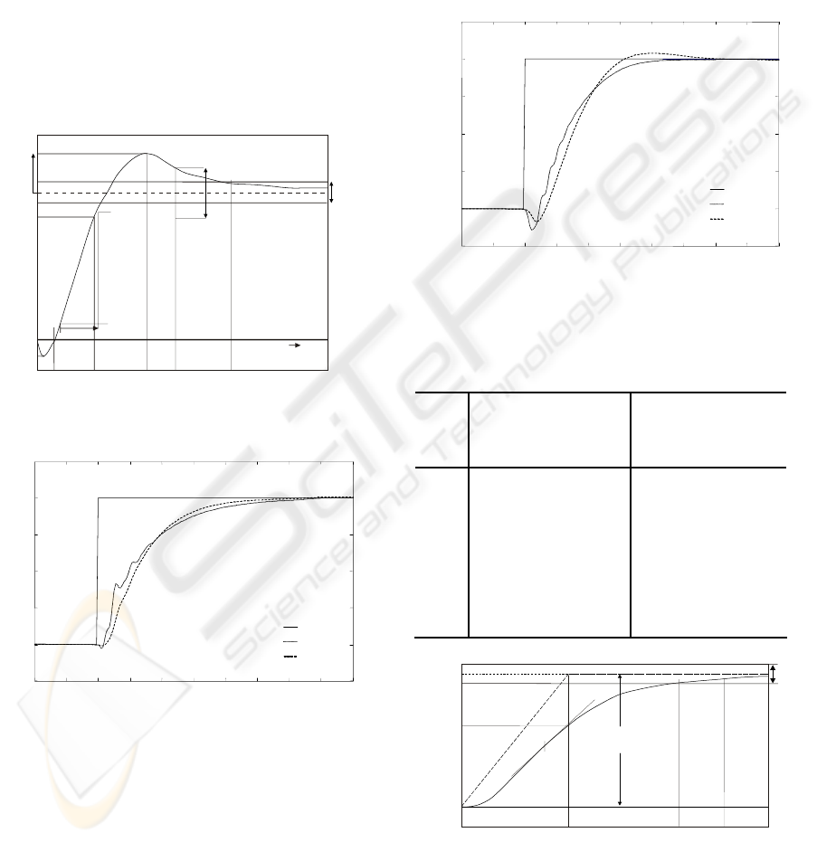
input signals. Jones et al have proposed a step and
ramp response for single unit operation (Jones,
Mansoor, Aris, Jones, Bradley, & King, 2004). This
step response specification for single unit operation
is expressed in Figure 8 and Table 1 (these are not
valid for commercial purposes). The most important
criterion is usually Test P1 for the primary response,
which requires that the station, under defined
conditions, achieves at least 90% of the demanded
step power change within 10s of initiation. Table 1
also shows that the over-shoot P
2
must not exceed
5% and the initial negative excursion P
6
(undershoot), associated with the non-minimum
phase response, must not exceed 2%.
Table 1: Specification of step response for advanced
control design at Dinorwig.
Test
Specification for single
unit operation.
Single unit response
with current governor.
P1
P
1
≥ 90% at t
p1
= 10s
81% at 10s, 90% at
13.7s
P2
P
2
≤ 5% and t
p2
≤ 20s No overshoot
P3
t
p3
= 25s for P
3
≤ 1% 25.9s
P4
t
p4
= 60s for P
4
≤ 0.5% 29.2s
P5
t
p5
= 8s 12.1s
P6
P
6
= 2% 1.75%
P7
t
p7
= 1.5s 0.88s
The neural PDF controller was connected to the
nonlinear model of the hydroelectric power plant.
The model is expressed in the per-unit system,
ICINCO 2008 - International Conference on Informatics in Control, Automation and Robotics
262
normalized to 300 MW and 50 Hz, and assumes a
Grid system with infinite busbars. A PI controller
with parameters fixed at K=0.1 and T
i
=0.12 (as
currently implemented in practice) is used as a basis
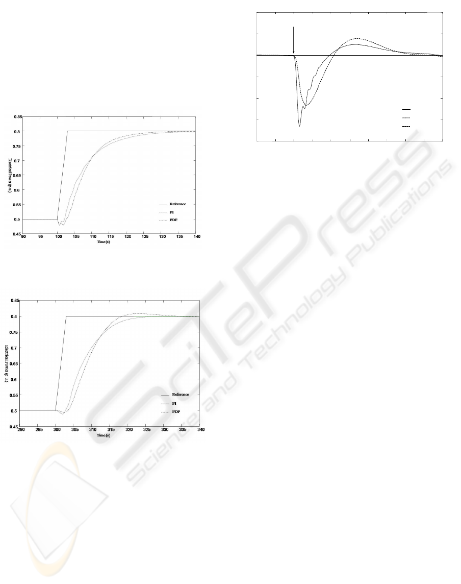
of comparison. Figure 9 shows small step responses
(0.04 p.u.) of hydroelectric plant under PI and neural
PDF controllers for one unit operational. Figure 10
shows small step responses (0.04 p.u.) of the power
station when six units are connected. In both cases,
the hydroelectric plant shows a better performance
under neural PDF controller; the response under the
neural PDF controller is 10% and 30% faster in one
unit operational and six units operational,
respectively. The undershoot is also reduced in both
cases when a PDF controller is driven the process.
t
initial power
target power
P
2
P
1
P
3
P
4
P
6
p5
t
p7
t
p1
t
p2
t
p3
t
p4
10%
Time
+
_
+
_
10%
Figure 8: Specifications for a response to a step change in
demanded power.
190 195 200 205 210 215 220 225 230 235 240
0.83
0.84
0.85
0.86
0.87
0.88
Time (s)
Electrical Power (p.u.)
PID
PDF
Reference
Figure 9: Step response of hydro plant under neural PDF
and PI controllers with one unit operational.
The ramp response specification for single unit
operation is expressed in Figure 11 and Table 2.
Again, the most important criterion is usually Test
Q1 for the primary response (t
q1
), which requires
that the station, under defined conditions, achieves at
least 90% of the demanded power change, ramp
amplitude (A
r
), within 15s of initiation. Table 2 also
shows that the maximum rate Q
2
must not be less
than 90% of the ramp rate and the steady-state
accuracy Q
3
must not be longer than 30s. Test Q
4
shows the effective under-delivery of power over the
period of the ramp (Jones, Mansoor, Aris, Jones,
Bradley, & King, 2004). The ramp response of the
nonlinear elastic model of Dinorwig is shown in
Figure 11.
490 495 500 505 510 515 520 525 530 535 540
0.83
0.84
0.85
0.86
0.87
0.88
Electrical Power (p.u.)
Time (s)
PID
PDF
Reference
Figure 10: Step response of hydro plant under neural PDF
and PI controllers with six units operational.
Table 2: Specification of ramp response for advanced
control design at Dinorwig.
Test Specification for a
single unit
operation
Single unit
response with
current PI control
Q
1
Q
1
≥90% at t
q1
=15s 14.7
Q
2
Q
2
=90% of 6
MWs
-1
1.8 MWs
-1
Q
3
t
q3
=30s for Q
3
≤1% 27
Q
4
None specified E(RMS)=3.09
MW for t
q4
=50s
time
t
q3
t
q4
initial power
target power
Q
1
Q
2
Q
3
t
q1
Ar
Figure 11: Specification for a ramp input power target.
Figure 12 shows large ramp responses (0.3 p.u.) of
hydroelectric plant under PI and neural PDF
EVALUATION OF NEURAL PDF CONTROL STRATEGY APPLIED TO A NONLINEAR MODEL OF A PUMPED
STORAGE Hydroelectric Power Station
263
controllers for one unit operational. Figure 13 shows
large ramp responses (0.3 p.u.) of the power station
when six units are connected. In both cases, the
hydroelectric plant shows a better performance
under neural PDF controller; the response under the
neural PDF controller is 15% and 13% faster in one
unit operational and six units operational,
respectively. When a PDF controller is driven the
plant, the under-shoot is also reduced for both cases.
Figure 12: Large ramp response of hydro plant under
neural PDF and PI controllers with one unit operational.
Figure 13: Large ramp response of hydro plant under
neural PDF and PI controllers with six units operational.
To evaluate the cross coupling interaction a 0.04
step was applied simultaneously at t=500 to units 2-
6 and the perturbation of unit 1 were observed.
Figure 14 shows that although the neural PDF
response has a higher overshoot, the PI response has
a longer settling time and a higher undershoots.
490 495 500 505 510 515 520 525 530 535 540
0.86
0.865
0.87
0.875
0.88
0.885
0.89
Electrical Power (p.u.)
Time (s)
A step is applied to units 2 to 6
PID
PDF
Reference
Figure 14: Cross coupling of hydro plant under PI and
neural PDF controllers.
6 CONCLUSIONS
The results have shown how the neural PDF can be
applied to a hydroelectric pumped-storage station to
improve its dynamic response. In particular, this
paper has shown that the step response of the system
with neural PDF is improved. Multivariable effects
have been taken into account to represent closely the
real plant. The close relation between penstocks has
been included into the nonlinear model. These are
promising results for the use of neural PDF in this
application and encourage us to address the issue of
robustness of the response in future work.
ACKNOWLEDGEMENTS
The authors wish to thank First Hydro Company for
their assistance. G. A. Munoz-Hernandez wishes to
thank “CONACyT” and the “Instituto Tecnológico
de Puebla” who have supported him in his
postdoctoral work.
REFERENCES
Aguado Behar, A. (2000). Topics on identification and
adaptive control (in Spanish). La Habana, Cuba:
ICIMAF.
Djukanovic, M. B., Calovic, M. S., Vesovic, B. V., &
Sobajic, D. J. (1997). Neuro-fuzzy controller of low
head hydropower plants using adaptive-network based
fuzzy inference system. IEEE Transactions on Energy
Conversion , 12, 375-381.
Garcez, J. N., & Garcez, A. R. (1995). A connectionist
approach to hydroturbine speed control parameters
ICINCO 2008 - International Conference on Informatics in Control, Automation and Robotics
264

tuning using artificial neural network. In IEEE (Ed.),
38th IEEE Midwest Symposium on Circuits and
Systems, 2, pp. 641-644.
Jones, D. I., Mansoor, S. P., Aris, F. C., Jones, G. R.,
Bradley, D. A., & King, D. J. (2004). A standard
method for specifying the response of hydroelectric
plant in frequency-control mode. Electric Power
Systems Research , 68, 19-32.
Kang, J. K., Lee, J. T., Kim, Y. M., Kwon, B. H., & Choi,
K. S. (1991). Speed controller design for induction
motor drivers using a PDF control and load
disturbance observer. IECON (pp. 799-803). Kobe,
Japan: IEEE.
Kundur, P. (1994). Power System Stability and Control
New York. New York, USA: Mc Graw Hil.
Mansoor, S. P. (2000). PhD. Thesis. Behaviour and
Operation of Pumped Storage Hydro Plants. Bangor,
U.K.: University of Wales, Bangor.
Mansoor, S. P., Jones, D. I., Bradley, D. A., & Aris, F. C.
(1999). Stability of a pumped storage hydropower
station connected to a power system. IEEE Power
Eng. Soc. Winter Meeting (pp. 646-650). New York,
USA: IEEE.
Mansoor, S. P., Jones, D. I., Bradley, D. A., Aris, F. C., &
Jones, G. R. (2000). Reproducing oscillatory
behaviour of a hydroelectric power station by
computer simulation. Control Engineering practice ,
8, 1261-1272.
Minsky, M. L., & Papert, S. A. (1988). Perceptrons:
Introduction to Computational Geometry. Cambridge,
USA: MIT Press.
Narendra, K. S., & Mukhopadhyay, S. (1996). Adaptive
control using neural networks and approximate
models. American Control Conference (pp. 355-359).
Seattle, USA: IEEE.
Rumelhart, D. E., McClelland, J. L., & group, T. P.
(1986). Parallel distributed processing: Explorations
in the microstructure of cognition (Vol. 1).
Cambridge, USA: MIT Press.
Shu-Qing, W., Zhao-Hui, L., Zhi-Huai, X., & Zi-Peng, Z.
(2005). Application of GA-FNN hybrid control system
for hydroelectric generating units. International
Conference on Machine Learning and Cybernetics. 2,
págs. 840-845. IEEE.
Werbos, P. J. (1974). PhD. Thesis: Beyond regression:
New Tools for Prediction and Analysis in the
Behavioral Sciences. Cambridge, USA: Harvard
University, Cambridge, MA.
Widrow, B., & Hoff, M. E. (1960). Adaptive switching
circuits. IRE WESCON Convention Record, 4, págs.
96-104.
Working group on prime mover energy supply, I. (1992).
Hydraulic turbine and turbine control model for
system dynamic studies. IEEE Transactions on Power
Systems , 7, 167-179.
Yin-Song, W., Guo-Cai, S., & Ong-Xiang. (2000). The
PID-type fuzzy neural network control and it's
application in the hydraulic turbine generators. Power
Engineering Society meeting. 1, págs. 338-343. IEEE.
EVALUATION OF NEURAL PDF CONTROL STRATEGY APPLIED TO A NONLINEAR MODEL OF A PUMPED
STORAGE Hydroelectric Power Station
265
