
MOTOR PARAMETERS INFLUENCE ON
STABILITY OF DRIVE FOR INDUSTRIAL ROBOT
Sorin Enache, Monica Adela Enache, Mircea Dobriceanu
Mircea Adrian Drighiciu and Anca Petrisor
Electromechanical Faculty, University of Craiova, 107 Decebal Street, 200440 Craiova, Romania
Keywords: Electrical drive, industrial robot, stability, asynchronous motor, parameters.
Abstract: This paper analyzes a driving system for an industrial robot from the stability point of view. For doing this,
an original analysis method has been conceived. The method has as starting point the two axes mathematical
model with equations written in per unit values. A Matlab program has been conceived with their help; this
program has led to results and conclusions detailed in this paper. Finally a series of experimental results
confirming the conclusions deduced with the new method are presented.
1 INTRODUCTION
The induction motors have been recognized for a
long time as being the most reliable electrical
machines, allowing an easy maintenance and
utilization in dangerous medium, being at the same
time cheap, easily to be built and having a high
power/weight ratio. Yet, the speed adjustment of the
squirrel cage induction motors is made with the help
of some relatively complicated static equipments, of
the voltage and frequency static converters.
The high cost of these ones is in a permanent
decrease owing to the achievements from the field of
power electronic components. Concomitantly with
the progresses of the power electronics, we watch
the introduction of the microelectronics in the
command and adjustment part of the power
converters.
Owing to the flexibility provided by the
microcomputers programming, it is possible to
achieve solutions of high complexity and reliability.
Owing to these progresses there have been
implemented some new multi-variable adjustment
techniques, field orientation, field accelerating etc.
All these aspects made the induction motor to
conquer new positions in variable speed drives.
This way, the power electronics has practically
reduced the problem of the use extension of the
induction motor supplied from a voltage and
frequency static converter, to a problem of
investment cost and economic efficiency.
The ever greater utilization of the induction motor as
an execution element in the automatic systems has
imposed an ever larger approach, in the speciality
papers, of the problems concerning the dynamic
regime of it.
This paper joins to this context, analyzing a few
aspects regarding the dynamic processes when
operating with variable frequency. So, first of all it is
necessary to use an adequate mathematical model
for performing a study in this field. The two axes
theory models are discussed in the analyzed case.
Starting from the conclusion that the stability is a
qualitative feature of the systems associated to their
dynamic behaviour, it also results that it is necessary
to analyze the stability of the converter-motor-robot
assembly and the motor parameters influence on it.
2 MATHEMATICAL MODEL
The equations system that is used has the following
form (Enache, 2005):
(
)
*
*
*
*
/**
*
s
s
s
rs
kss
j
dt
d
ks Ψ+
Ψ
+Ψ−Ψ=
ωω
(
)
()
/*
**
*
/*
*/*
0
r
s
r
sr
kr
j
dt
d
ks Ψ−+
Ψ
+Ψ−Ψ=
ωω
(
)
*
/*
*
*
/**
*
Im
r
rs
rt
m
x
k
dt
d
h −
⎥
⎦
⎤
⎢
⎣
⎡
ΨΨ−=⋅
ω
(1)
271
Enache S., Adela Enache M., Dobriceanu M., Adrian Drighiciu M. and Petrisor A. (2008).
MOTOR PARAMETERS INFLUENCE ON STABILITY OF DRIVE FOR INDUSTRIAL ROBOT.
In Proceedings of the Fifth International Conference on Informatics in Control, Automation and Robotics - ICSO, pages 271-274
DOI: 10.5220/0001477002710274
Copyright
c
SciTePress
where m
r
is the resistant torque corresponding to the
industrial robot.
3 SIMULATIONS:
QUANTITATIVE RESULTS
A Matlab program for the stability analysis has been
conceived.
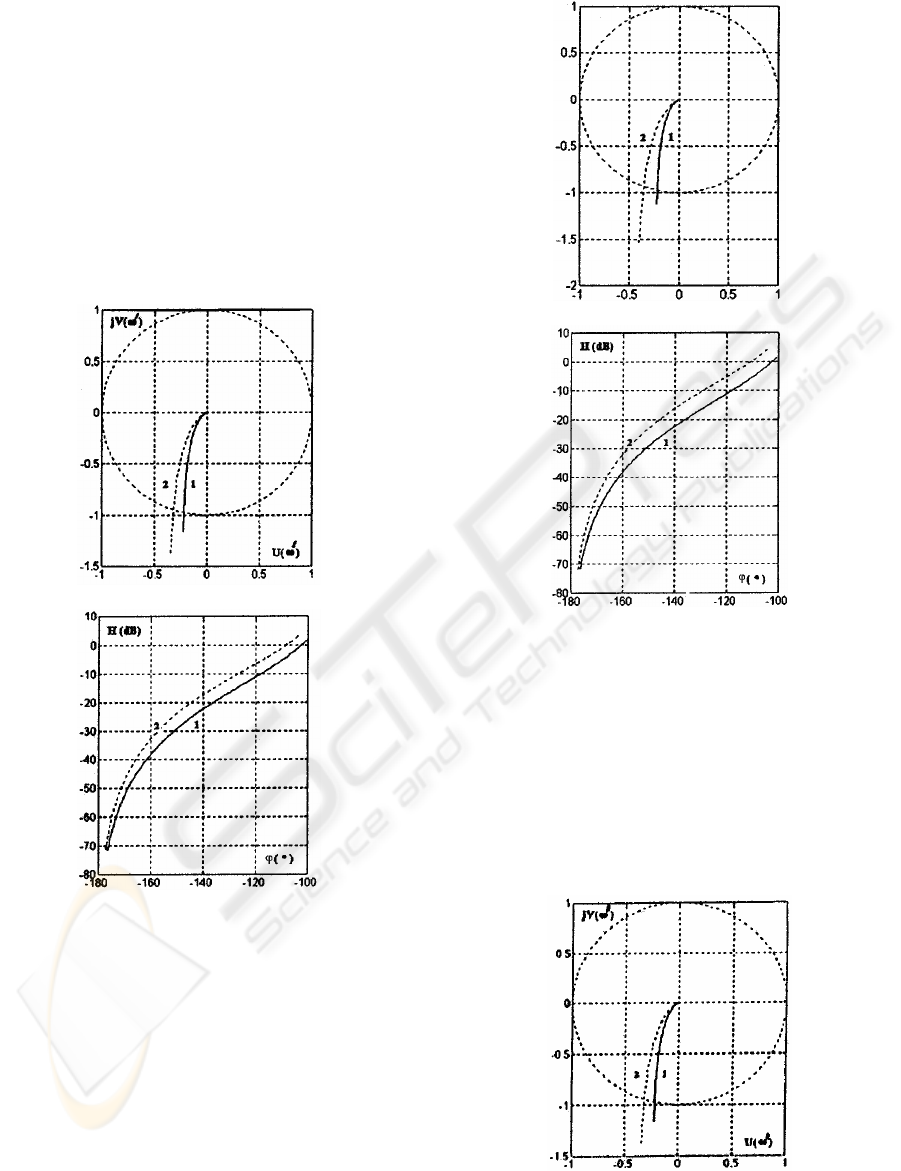
The representations from Figs. 1, 2 and 3 have
been obtained by running this program, for the
concrete case of a motor rated at 1,1 kW.
a)
b)
Figure 1: Transfer locus (a) and amplitude-phase
characteristics (b) obtained in the case of the inductances
modification:
529,0=
s
L
H (1) and
549,0=
s
L
H (2).
a)
b)
Figure 2: Transfer locus (a) and amplitude-phase
characteristics (b) obtained in the case of the inductances
modification:
528,0
/
=
r
L
H (1) and
548,0
/
=
r
L
H (2).
There must be also mentioned the importance of
the introduced method resulting from the possibility
to emphasize the machine parameters influence and
especially the inertia moment influence, on stability
when operating at variable frequency, fact that
provides originality to this method.
a)
ICINCO 2008 - International Conference on Informatics in Control, Automation and Robotics
272
b)
Figure 3: Transfer locus (a) and amplitude-phase
characteristics (b) obtained in the case of the inductances
modification:
498,0=
sh
L
H (1) and
558,0=
sh
L
H (2).
In order to catch quantitatively these
interdependences the following table has been filled.
Table 1: Absolute values and phase margins.
Param.
Absolute
value
Per unit
param.
Per unit
value
Phase
margin [
0
]
s
L
0,549
*
s
x
2,2735 69,13
/
r
L
0,548
/*
r
x
2,2694 75,31
sh
L
0,558
*
1m
x
2,3104 71,32
These results help us to emphasize a few important
conclusions regarding the resistances influence on
the studied system stability:
- the increase of the inductance
s
L leads to the
stability decrease;
- at the same time with the rotor inductance
increase the system stability decreases;
- the increase of the main inductance has a
stabilizing effect.
4 EXPERIMENTAL CIRCUIT
In order to confirm the previous conclusions, a series
of experimental tests have been performed; a few of
them are detailed further on.
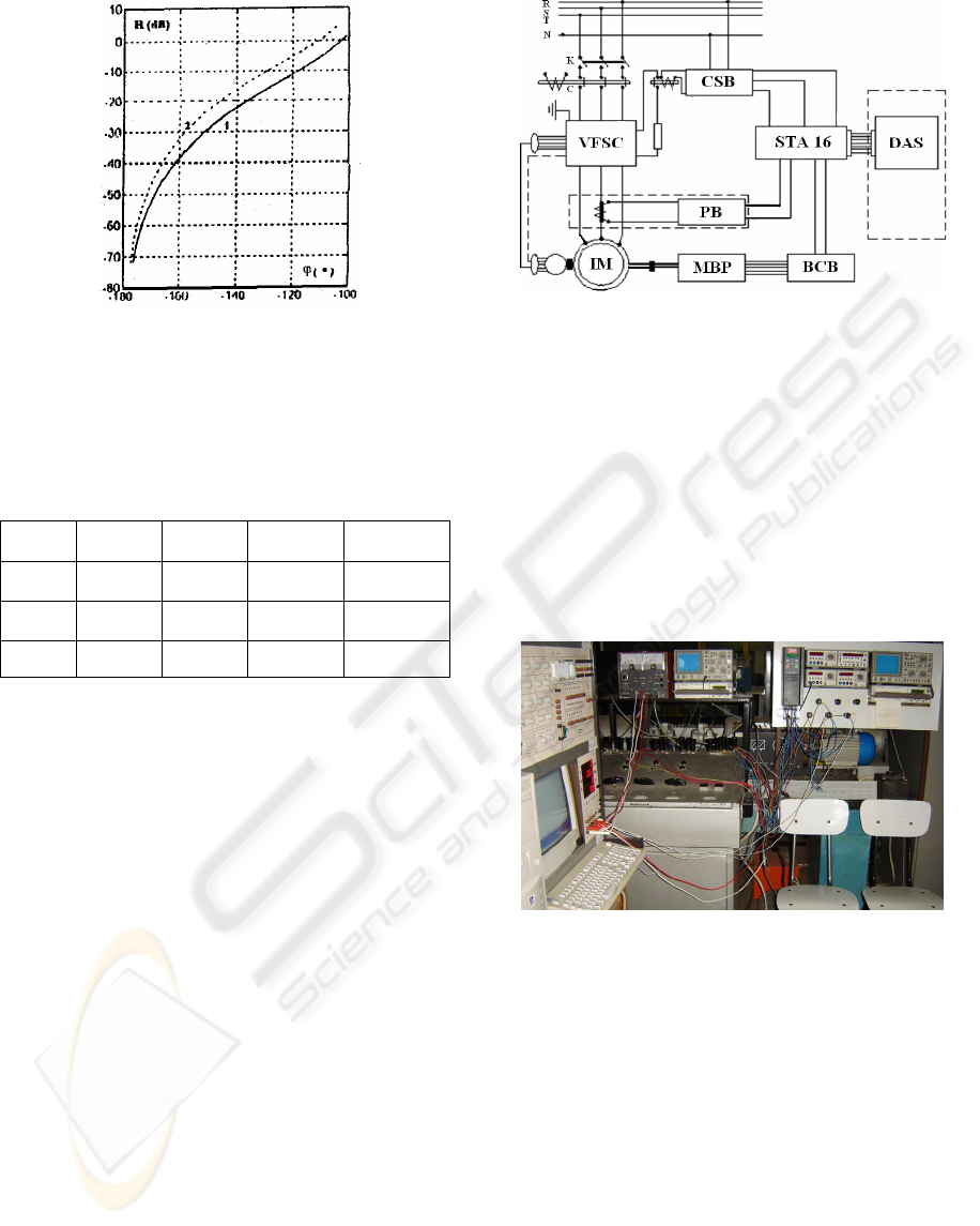
Thus, the experimental circuit has the structure
depicted in the following figure.
Figure 4: Scheme of the experimental circuit.
The notations have the following meaning:
IM – induction motor;
VFSC – voltage and frequency static converter;
DAS – data acquisition board;
CSB – command and synchronization block;
PB – protection block;
MPB – magnetic powder break;
BCB – brake command block;
STA 16 – connection block.
A picture of this circuit is depicted for conformity.
Figure 5: Picture of experimental circuit.
In order to obtain the determinations in dynamic
regime the experimental circuit depicted before has
been carried out, having a data acquisition board
DAS as a central element (Enache, 2007). This high
speed analogical and digital interface has been
assembled inside a computer. Both the acquisition
and the adequate data processing are controlled with
the help of a program conceived in Matlab.
5 EXPERIMENTAL RESULTS
A series of graphic results have been obtained with
the help of the acquisition program; the following
figures are depicted further on.
MOTOR PARAMETERS INFLUENCE ON STABILITY OF DRIVE FOR INDUSTRIAL ROBOT
273
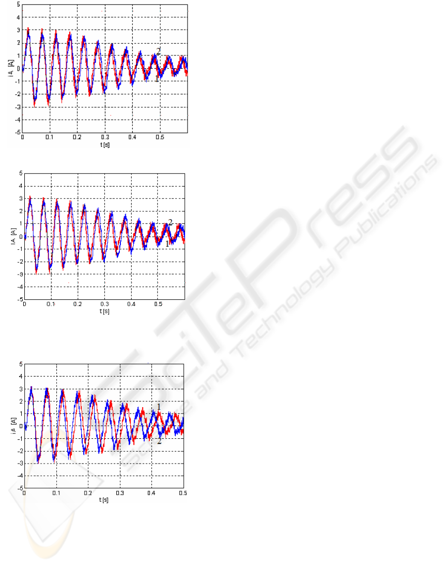
Figure 6: Graphic dependences corresponding to the cases
L
s
=0,529 H (1) and L
s
=0,549 H (2).
Figure 7: Graphic dependences corresponding to the cases
/
r
L =0,528 H (1) and
/
r
L =0,548 H (2).
Figure 8: Graphic dependences corresponding to the cases
L
sh
=0,498 H (1) and L
sh
=0,438 H (2).
These graphics lead to the following conclusions:
- when the value of the stator inductance
increases the transient process duration
increases (the stability decrease);
- the increase of the rotor inductance also
involves the increase of the transient process
duration (the stability decreases);
- the decrease of the main inductance value
determines a faster stabilization of the process
(stability increase).
These conclusions confirm the theoretical analysis
performed before.
REFERENCES
Delemontey, B., Jacquot, B., Iung, C., De Fornel, B.,
Bavard, J., 1995. Stability Analysis and Stabilisation
of an Induction Motor Drive with Input Filter. In:
Proccedings of 6
th
European Conference on Power
Electronics and Applications, Sevilla, Spain, pp. 121-126.
Enache, S., Vlad, I., Enache, M.A., 2005. Considerations
Regarding Influences of Induction Motor Resistances
upon Stability in case of Operation at Variable
Frequency. In: Proccedings of SIELMEN’05,
Chisinau, Moldova, Vol.2, ISBN GEN 973-716-208-0,
2005, pp 660-663.
Enache, S., Prejbeanu, R., Campeanu, A., Vlad, I., 2007.
Aspects Regarding Simulation of the Saturated
Induction Motors Control by the Voltage Inverter
Commanded in Current. In: Proceedings of IEEE
Region 8, EUROCON2007, Warsaw, Poland, 9-12
september 2007, IEEE Catalog Number: 07EX1617C,
ISBN:1-4244-0813-X, Library of Congress:
2006937182, p. 1826.
Enache, S., Campeanu, A., Vlad, I., Enache, M.A., 2007.
A New Method for Induction Motor Stability Analysis
when Supplying at Variable Frecquency,. In:
Proceedings of ISTASC’07, Athens p.126.
Lin, J.L., Shiau, L.G., 2000. On Stability and Performance
of Induction Motor Speed Drives with Sliping Mode
Current Control. Asian Journal of Control, Vol. 2, No.
2, pp 122-131.
Lipo, T., 1993 Stability Analysis of a Rectifier-inverter
Induction Motor Drive. IEEE Transaction on Industry
Applications, 88, 1, 1993, pp 57-68.
Subrahmanyam, V., Surendram, K., 1996. Stability
Analysis of Variable Frequency Induction Motors
Using D - Decomposition Method. Electric Machines
and Power Systems, 11, pp. 105-112.
Suwankawin, S., Sangwongwanich, S., 2002. A speed-
sensorless IM drive with decoupling control and
stability analysis of speed estimation. IEEE
Transactions on Industrial Electronics, vol. 49, no. 2,
pp 444-455.
Vas, P., 1990. Vector Control of A.C. Machines,
Clarendon Press.
DAS 1601 - Operating Manual, Keithley Metrabyte, 2002.
ICINCO 2008 - International Conference on Informatics in Control, Automation and Robotics
274
