
ACTIVE SECURITY SYSTEM FOR AN INDUSTRIAL ROBOT
BASED ON ARTIFICIAL VISION AND FUZZY LOGIC PRINCIPLES
B. Fevery, B. Wyns, L. Boullart
Department of Electrical Energy, Systems and Automation, Ghent University, Ghent, Belgium
J. R. Llata Garc
´
ıa, C. Torre Ferrero
Control Engineering Group, Electronic Technology and Automatic Systems Department
University of Cantabria, Santander, Spain
Keywords:
Active security, application, artificial vision, fuzzy logic, real-time, robot control.
Abstract:
An active security system assures that interacting robots don’t collide or that a robot operating independently
doesn’t hit any obstacle that is encountered in the robots workspace. In this paper, an active security system
for a FANUC industrial robot is introduced. The active security problem where one robot needs to avoid
a moving obstacle in its workspace is considered. An obstacle detection and localization mechanism based
on stereoscopic vision methods was successfully developed. To connect the vision system, an operator’s pc
and the robot environment a real-time communication is set up over Ethernet using socket messaging. We
used fuzzy logic for intelligent trajectory planning. A multitask oriented robot application in the KAREL
programming language of FANUC Robotics was implemented and tested.
1 INTRODUCTION
In industrial settings, robots often work on valuable
products and with expensive tools. When more robots
are working together on one assignment, a collision
free interaction of the robot arms needs to be guar-
anteed at all time. Systems that establish collision
free robot interaction are identified as Active Security
Systems (ASSYS). ASSYSs can also be situated in
the domain of interaction between industrial manipu-
lators and human operators, where the physical safety
of the operator, rather than an economical concern,
constitutes the necessity for the design of an appro-
priate security system.
The key principle of ASSYSs is the vigilance of
the work area of cooperating robots and the streaming
of information about events that are unexpected for
each robot. This contrasts with a strategy where every
robot is seperately programmed to execute its task and
where interaction signals are sent between robots over
rigid communication media.
Safe robot motion is typically guaranteed by the
use of a sensor system. A camera network based
human-robot coexistence system was already pro-
posed in (A.J. Baerveldt, 1992) and a safety system
also using a network of cameras and with path re-
planning in an on-line manner was presented in (D.
Ebert et al., 2005). In this paper, we present the setup
of a basic vision system to detect and positionally
reconstruct obstacles in the robot’s workspace. The
stereoscopic vision techniques applied in the design
of the vision system will be presented in section 2.
In literature, some researchers focus on the direct
kinematics of robot manipulators. Using the differ-
ences between actual and goal angular configuration
of every axis, output actions for every axis’s motor are
produced taking into account an obstacle’s configura-
tion in the two or three dimensional space. In this
paper, we will present a security system that controls
the motional actions of an industrial FANUC Robot
Arc Mate 100iB with six degrees of freedom and a
circular range of 1800 millimeters. Instead of giving
commands to every axis’s motor, positional and ro-
tational configuration of the robot arm will be calcu-
lated along the nodes of an alternative path around one
detected obstacle. Intelligent path planning is done by
using a fuzzy logic control system. A rule base com-
posed of linguistic if-then implications is used to sim-
ulate human reasoning in decision taking. The fuzzy
system produces a set of alternative positions and ro-
tational configurations that assure collision free mo-
tion continuation towards a final location. Fuzzy logic
17
Fevery B., Wyns B., Boullart L., R. Llata García J. and Torre Ferrero C. (2008).
ACTIVE SECURITY SYSTEM FOR AN INDUSTRIAL ROBOT BASED ON ARTIFICIAL VISION AND FUZZY LOGIC PRINCIPLES.
In Proceedings of the Fifth International Conference on Informatics in Control, Automation and Robotics - RA, pages 17-23
DOI: 10.5220/0001477300170023
Copyright
c
SciTePress

is popular due to its simplicity and hands-on, intuitive
design of the control strategy and was successfully ap-
plied by preceding authors, e. g. in (Bischoff, 1999),
to build active safety systems for robots. In this paper,
a three dimensional obstacle avoidance strategy will
be introduced that is founded on the idea of repelling
and attracting forces (P. Zavlangas et al., 2000). The
design of a fuzzy logic controller will be highlighted
in section 3.
Although specialised solutions exist for each com-
ponent of the proposed ASSYS, the goal in this paper
was to build such a system using only basic compo-
nents communicating over an Ethernet network. No
multiple robot interaction was assumed and due to the
early stage of the investigation, the vision system was
only designed to make the robot avoid collision with
a single, however dynamically moving, obstacle. At-
tention was also given to the time performance of the
vision system.
To make the industrial FANUC robot move along
an alternative path in an on-line manner, a robot ap-
plication needed to be programmed in the proper pro-
gramming language KAREL of FANUC Robotics. A
multitask oriented design in the KAREL language
assures that alternative positions can be read in by
the robot’s system and subsequently moved to by the
robot arm. The architecture of the robot application,
as well as details on the real-time communication sys-
tem established over Ethernet, will be commented in
section 4. In section 5 results and drawbacks of the
designed ASSYS are commented.
2 ARTIFICIAL VISION
2.1 3D Object Reconstruction
Stereoscopic vision applications intent to reconstruct
the 3D location of characteristic object points. From
(Torre Ferrero, 2002) an analytical method was taken
that allows for a unique 3D reconstruction of an object
point P, knowing the pixel sets (u
1
, v
1
) and (u
2
, v
2
) of
P’s projection into two different image planes I
1
and
I
2
. The camera’s projection matrices, that are com-
posed of the camera’s extrinsic and intrinsic parame-
ters (Gonzal
´
ez Jim
´
enez, 1999), are also needed for re-
construction. These parameters were obtained for ev-
ery camera by applying a camera calibration method
based on (J. Heikkil
¨
a et al., 1997). For more details on
camera projection principles and reconstruction meth-
ods, please consult (Gonzal
´
ez Jim
´
enez, 1999) and
(Torre Ferrero, 2002).
2.2 Camera Setup of the Vision System
A triplet of network cameras was installed to watch
the robot’s workspace. Camera images can be ob-
tained by sending an image request signal to their IP
address over a Local Area Network (LAN). For ev-
ery camera, a video stream of images using ActiveX
components is activated. Images are taken out of the
video stream and saved as image matrices of dimen-
sion 480x640x3 in the Red Green Blue (RGB) image
space. A pc is used to perform image processing op-
erations. The cameras were collocated in a triangular
pattern and mounted on the ceiling above the robot’s
workspace.
2.3 Object Detection and
Reconstruction Methods
In industrial settings, image processing times need to
be small. Preliminary knowledge about the object’s
color and shape is therefore often used to detect obsta-
cles in the robot’s workspace as quickly as possible.
For the experimental setup of our vision system, we
worked with a foam obstacle of parallelepiped struc-
ture. The motion of the obstacle is achieved by simply
dragging the foam into the robot’s workspace with a
rope. Because it is not within the scope of this paper,
no attention was given to the detection of the robot’s
arm, nor to the detection of humans or objects of other
form than a parallelepiped. In the next sections, we
will introduce the vision techniques that were used
for the detection of a moving obstacle and for the re-
construction of its 3D position. The reconstruction
method is based on the technique of epipolar lines,
which form a useful geometric restriction in vision
applications.
2.3.1 Obstacle Observation
The obstacle of parallelepiped form is detected in an
image by converting this image to binary form and
subsequently check for the presence of contours of
squared form, using a simple criterion that relates a
square’s perimeter to its area. The presence of the ob-
stacle is checked by drawing the image of one camera
out of the activated video stream every 50 millisec-
onds and by applying the square detection criterion.
When a moving obstacle is detected for the first
time in the workspace, the ASSYS halts all robot mo-
tion. Only if the obstacle stops moving within a cer-
tain number of time frames after it had first been de-
tected, the robot will resume its motion, now moving
around the obstacle. By taking subsequent images out
of the video stream of the same camera and resting
ICINCO 2008 - International Conference on Informatics in Control, Automation and Robotics
18

.
.
.
.
.
.
.
.
C
3
I
l
p
1
C
1
C
2
p
2
P
21
P(x, y, z)
P
2m
E
2
E
3
p
3
E
31
E
3m
E
3j
I
3
I
2
Figure 1: Pixel correspondence algorithm.
two subsequent image matrices, the system checks if
the object has stopped moving. As soon as this condi-
tion holds, images are drawn out of the video stream
of the two other cameras and the 3D reconstruction
of the obstacle is initiated. We typically reconstruct
the 3D location of the obstacle’s four upper corners.
These characteristic object points are determined by
applying a Canny edge detector (Gonzal
´
ez Jim
´
enez,
1999) and a corner detection operator on the three im-
ages.
Once characteristic points -true and also false ob-
ject corners due to image noise or nearby objects- are
detected, an algorithm is applied to determine corre-
sponding corners. This problem boils down to finding
for every upper corner of the obstacle in a first image,
the location of the same corner in the second and third
image.
2.3.2 Calculation of Pixel Correspondences
The applied algorithm is based on the geometric re-
striction of the epipolar line: an image point P that
is projected onto a pixel in a first image can only be
projected onto one line of pixels in a second image.
We aim to find three pairs of pixel coordinates of one
point in space that is projected into three images I
1
,
I
2
and I
3
. This problem is identified as the search for
pixel correspondences. The algorithm can briefly be
explained as follows, according to the notations of fig-
ure 1. The image point p
2
in the second image I
2
that
corresponds to the point p
1
in the first image I
1
has
to be situated on the epipolar line E
2
associated to p
2
.
Characteristic pixels of I
2
that are located sufficiently
close to this epipolar line are selected as correspon-
dence candidates P
2i
in I
2
. When the epipolar lines
E
3 j
associated to all correspondence candidates P
2i
are constructed in a third image I
3
, this results in a
number of intersections p
3k
in I
3
between the epipolar
lines associated to the set P
2i
and the epipolar line E
3
associated to p
1
. The intersection that coincides or is
located sufficiently close to one of the characteristic
points in I
3
, results in the unique corresponding pixel
triplet {p
1
, p
2
, p
3
}. Epipolar line pixel equations from
(Torre Ferrero, 2002) were used to construct epipolar
lines.
As soon as the corresponding corner pixels are
found in the three camera images, the pixel correspon-
dences are used to calculate the obstacle’s 3D location
in space, as described in section 2.1. False pixel cor-
respondences, that originated from detected corners
not belonging to the object, can be discarded because
the resulting 3D positions don’t fall within the range
in which the obstacle is expected to be encountered.
The obstacle’s 3D location in space is used as an input
of the fuzzy logic controller that calculates an alterna-
tive trajectory.
3 FUZZY LOGIC CONTROL
3.1 Introduction
A Fuzzy Logic Controller (FLC) is a useful tool to
transform linguistic control strategies based on exper-
tise into an automatic control strategy (O. Cordon et
al., 2001). The basic idea is to assign linguistic la-
bels to physical properties. The process that converts
a numerical value into a linguistic description is the
fuzzification process. Using a rule base that simulates
human reasoning in decision taking, a number of lin-
guistic control actions is computed and subsequently
defuzzified or converted to numerical control actions.
For more information and a detailed description on
FLCs, please consult (O. Cordon et al., 2001).
A pneumatically controlled tool was mounted on
ACTIVE SECURITY SYSTEM FOR AN INDUSTRIAL ROBOT BASED ON ARTIFICIAL VISION AND FUZZY
LOGIC PRINCIPLES
19
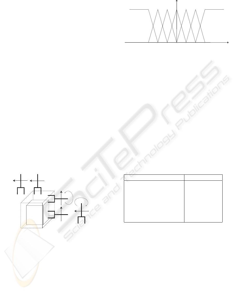
the robot arm. The term End Effector is used to indi-
cate this tool, that is depicted in figure 2 for different
configurations. In robot terminology, the central point
of the End Effector is called the Tool Center Point
(TCP). The dots between the ends of the End Effector
in figure 2 represent this TCP.
3.2 Fuzzy Avoidance Strategy
A fuzzy rule containing two types of actuating forces
was designed. An attracting force proportional to the
1D distance differences between actual TCP coordi-
nates and final location coordinates causes the FLC to
output distance increments towards the final location.
A repelling force describing the distance to the obsta-
cle’s sides deactivates the attracting force and invokes
specific avoidance actions that have to be undertaken
by the robot’s End Effector to avoid collision with the
obstacle.
Further on, it will be explained how safety zones
are constructed around the obstacle, based on the dis-
tance differences between the TCP and the obstacle’s
sides. When the robot’s TCP enters one of these
safety zones around the obstacle, two types of avoid-
ance actions are undertaken. Rotational actions guar-
antee the End Effector’s orthogonal position to the ob-
stacle’s sides and translational actions assure an accu-
rate avoidance in position. This idea is depicted in
figure 2.
5
4
3
2
.
.
.
.
.
1
+90° y
-
90° y
Very Close
Figure 2: Fuzzy avoidance strategy.
3.3 Inputs to the Fuzzy Logic Controller
The inputs of the FLC consist of two types. A first
type describes 1D distance differences between actual
TCP coordinates and final location coordinates, while
the second input indicates if the TCP is near to one of
the obstacle’s sides. The first input is related to the at-
tracting influence and the second one to the repelling
influence. It will now be explained how both types of
inputs to the FLC are composed.
The distance between final location and TCP can
be described in linguistic terms as e.g. Close or Far.
Close
Neg
Far
Neg
VClose
Neg
VClose
Pos
Close
Pos
Far
Pos
∆r
Figure 3: MFs for fuzzy sets of attracting influence.
For a given numeric value of distance to the final lo-
cation, each of the linguistic labels will be true with
a certain value in the range [0, 1]. This value will
be determined by the Membership Function (MF) of
the specified linguistic distance label. Figure 3 illus-
trates the MFs of the labels that describe the distance
difference ∆r in x, y and z direction between the coor-
dinates of the Tool Center Point and the final location
coordinates. MFs of triangular and open trapezoidal
form were chosen because they are easy to implement
in programming applications and require small evalu-
ation times. The central triangular represents the MF
for Contact with the obstacle. Table 1 indicates the
1D distance descriptions in coordinates r = x, y and z
towards the final desired configuration.
Table 1: Labels for attracting influence.
Linguistic label Short notation
Goal Far Negative GFar Neg r
Goal Close Negative GCl Neg r
Goal Very Close Negative GVCl Neg r
Goal Reached Goal r
Goal Very Close Positive GVCl Pos r
Goal Close Positive GCl Pos r
Goal Far Positive GFar Pos r
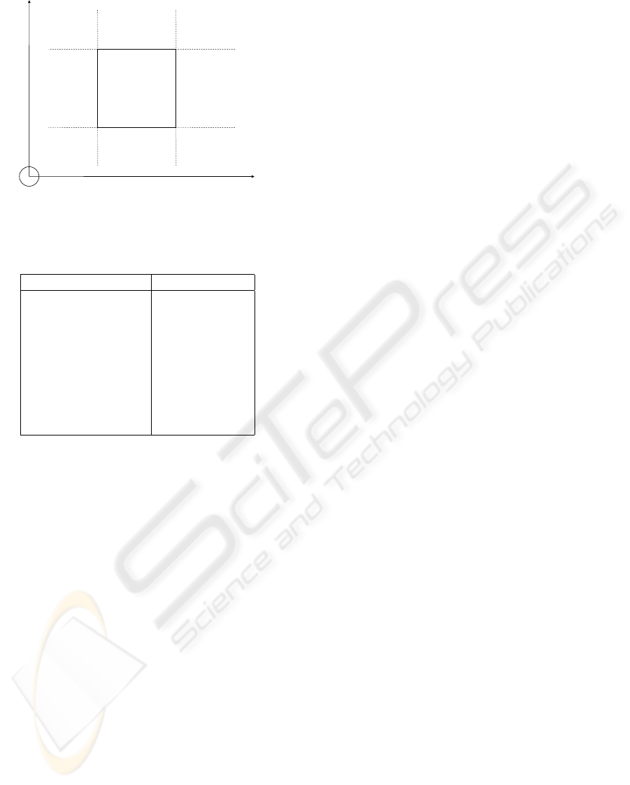
The second FLC input is related to the repelling
force. To understand how these FLC inputs originate,
we make the following consideration. If the robot’s
TCP is Very Close to the positive x side of the obsta-
cle, this means it is close to the positive x bound of
the obstacle AND: within the y and z range OR within
the y range and very close to the positive z bound OR
... . Figure 4 illustrates this idea for the construction
of the label Very Close Positive x.
The distance differences ∆s (s = x, y and z-
dimension) represent the distances of the TCP to the
closest obstacle bound in the considered coordinate.
For the example of figure 4, the considered label
needs to be evaluated using AND and OR logical oper-
ators. Table 2 represents distance difference descrip-
tions towards the sides of the obstacle.
ICINCO 2008 - International Conference on Informatics in Control, Automation and Robotics
20
Z
Y
X
VCl Pos ∆y
VCl Neg ∆z
VCl Pos ∆y
Contact ∆z
VCl Pos ∆y
VCl Pos ∆z
Contact ∆y
VCl Neg ∆z
Contact ∆y
Contact ∆z
Contact ∆y
VCl Pos ∆z
VCl Neg ∆y
VCl Neg ∆z
VCl Neg ∆y
Contact ∆z
VCl Neg ∆y
VCl Pos ∆z
VCl Pos ∆x
Figure 4: Construction of label Very Close Positive x.
Table 2: Labels for repelling influence.
Linguistic label Short notation
Far Negative Far Neg ∆s
Not Close Negative NCl Neg ∆s
Close Negative Cl Neg ∆s
Very Close Negative VCl Neg ∆s
Contact Contact ∆s
Very Close Positive VCl Pos ∆s
Close Positive Cl Pos ∆s
Not Close Positive NCl Pos ∆s
Far Positive Far Pos ∆s
Note that, according to the idea of figure 4, the
labels of table 2 have three-variable MFs, because
they are all composed of one dimensional MFs for
coordinate differences ∆r (r = x, y and z) towards the
obstacle’s boundary coordinates. These 1D MFs are
similar to the ones for the attracting forces depicted
in figure 3. Next step is to construct safety zones
around the obstacle, as shown in figure 2 for the label
Very Close. Analogously, zones Close and Not Close,
and an outer region Far, complementary to the inner
zones, are constructed.
To fuzzify the entrances of the Fuzzy Inference
System, we used a singleton fuzzificator (J. R. Llata
Garc
´
ıa et al., 2003).
3.4 Design of a Rule Base
The basic principle of the rule base is the deactivation
of the attracting influence -determined by the distance
to the final location- when the repelling influence is
triggered. Taking this into account, logical rules for
closing up to the final location can be constructed.
For the rules related to the repelling influence, we
can state that the designer of the rule base is free to
choose the direction and sense of the avoidance ac-
tions. We decided to undertake an avoidance action
in positive z direction when the TCP closes up to the
(Very) Close x or y, Negative or Positive side of the
obstacle.
The avoidance action for the (Very) Close z, Pos-
itive or Negative side, is decided upon by a criterion
that checks the distance difference in x and y coordi-
nate of the TCP’s current position and the final loca-
tion coordinates. If the distance difference is bigger
in the x direction, then an avoidance action in x is un-
dertaken, otherwise in y direction.
As soon as the TCP enters the safety zone Not
Close, a rotation of -90
◦
or +90
◦
around the appro-
priate axis of a fixed coordinate system needs to be
undertaken, to prevent the End Effector from hitting
the obstacle (see figure 2).
To resolve the fuzzy intersection operator used for
the composition of rule premises and for the impli-
cation on rule consequents, we used a T-norm of the
product type. In the aggregation of rule consequents
an S-norm for the fuzzy union operator was chosen.
We implemented a maximum operator as this S-norm
to save in processing time.
Given an initial and final position and an obsta-
cle’s location supplied by the vision system, the FLC
outputs a set of positional and rotational configura-
tions that guarantee collision free motion towards the
final location.
3.5 Outputs of the FLC
Fuzzy outputs of the Sugeno singleton type (J. R.
Llata Garc
´
ıa et al., 2003) were used for defuzzifica-
tion. Depending on the output of a rule, a specific
value can be assigned to the considered system out-
put. The designer of the FLC is free to determine the
size of the output actions.
Upon detection of an obstacle and halting of robot
motion, the TCP’s current position is sent by the
robot’s operational system over a socket connection
to the artificial intelligence system as a start point
for the calculation of an alternative path. Alternative
positions and rotational configurations are then sent
back over the socket in data packages that contain the
desired coordinates of the TCP and the desired rota-
tional configuration of the End Effector with respect
to the fixed coordinate system.
ACTIVE SECURITY SYSTEM FOR AN INDUSTRIAL ROBOT BASED ON ARTIFICIAL VISION AND FUZZY
LOGIC PRINCIPLES
21
4 EXPERIMENTAL SETUP
4.1 Real-time Communication
Robotic control applications often have cycle times
of typically hundreds of microseconds. When oper-
ational data needs to be exchanged between a robot
and an operator’s pc, the fastness and the guarantee
of data transmission is of utmost importance. For
many years, Ethernet was banned as a communication
medium from the industrial work floor, for data pack-
ages that are sent over the Ethernet by devices con-
nected to a same Local Area Network can collide and
be lost, due to the network’s media access control pro-
tocol CSMA/CD (Van Moergestel, 2007). Nowadays,
Fast Ethernet switches can be used to isolate network
devices into their own collision domain, hereby to-
tally eliminating the chance for collision and loss of
data packages. Ethernet switches together with the
development of Fast Ethernet (100Mbps) and Giga-
bit Ethernet (1Gbps) have made Ethernet popular as
a real-time communication medium in industrial set-
tings (Decotignie, 2005).
To establish the Ethernet communications in the
ASSYS, we used so called Ethernet sockets. Sockets
are software entities that are assigned to a combina-
tion of communication port and IP address, so that
they can be used by a client and a server device to
communicate over a LAN. In our setup, this LAN was
created by a Fast Ethernet switch. The exchange of all
data packages between the industrial FANUC Robot
Arc Mate 100iB and a pc running the vision and fuzzy
logic applications is performed by socket messaging.
4.2 Multitask Robot Application
A multitask oriented active security application was
developed and tested in KAREL, the programming
language of FANUC Robotics for advanced user ap-
plications. A motion task executes a normal opera-
tion trajectory until a condition handler is triggered
by the detection signal that was received through an
Ethernet socket by a concurrently running communi-
cation task. When this condition handler is triggered,
robot motion is halted within a time that is accept-
ably small and the TCP’s current position is sent by
the communication task to the operator’s pc, where
the FLC calculates the first alternative positions and
sends them back over the opened socket connection to
the communication task. An interrupt routine for mo-
tion along the alternative path is then invoked in the
motion task. The robot axes’s motors start accelerat-
ing immediately. Meanwhile, the communication task
completes the reading in of subsequent alternative po-
sitions and rotational configurations. Motion contin-
ues until the original final location is reached. The
KAREL application is written in a non-cyclic way.
Upon reaching the final position, program execution
is aborted. Coordination between the motion task and
the communication task was realised by the use of
semaphores. The artificial vision system, the FLC and
the robot control application in KAREL were tested in
an integrated way.
5 RESULTS AND DISCUSSION
The obstacle is dragged into the robot’s workspace
when the robot arm is close to the leftmost or right-
most point of its regular trajectory. Absence of the
robot’s arm in the central zone of the workspace is
necessary for correct obstacle detection because the
robot arm would deform the binary image of the ob-
stacle’s squared contour. Further development of the
vision system is therefore needed to distinguish the
robot arm from the obstacle in order to be able to sig-
nal obstacle presence in all operational situations. In
an advanced stadium, detection criteria for human op-
erators can also be elaborated.
However, if the robot arm is occulting one of the
obstacle’s upper corners in one of the three images,
performing an accurate reconstruction of the obsta-
cle’s 3D location is still possible, since a free view on
three of the four upper corners in all images is suffi-
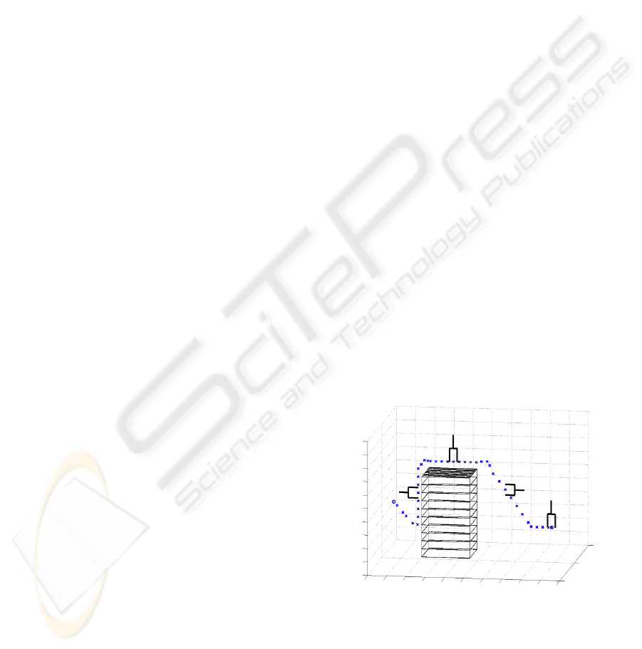
cient for the reconstruction. The parallelepiped in fig-
ure 5 depicts the result of the vision system and fuzzy
logic path planning.
Figure 5: Alternative trajectory around reconstructed obsta-
cle.
With distance increments of 50 millimeter in the
FLC we typically obtained a number of 40 alterna-
tive positions. The designer of the FLC is free to
choose the size of the translational increments larger
or smaller and in a rather intuitive way. However, a
ICINCO 2008 - International Conference on Informatics in Control, Automation and Robotics
22

thorough study can be performed making a trade-off
between small increments and thus larger calculation
times and larger robot processing times or large dis-
tance increments and thus smaller calculation times
and robot processing times. This last option impli-
cates however that the safety zones around the obsta-
cle need to be bigger and that longer trajectories have
to be completed by the robot tool before it reaches
the final location. For industrial settings, where small
robot motion execution times are of utmost impor-
tance, this trade-off study is an interesting topic for
future research. More specifically, a time efficient and
distance optimal path construction algorithm can be
designed.
The FLC only takes the TCP’s position as an in-
put. Collision of the robot’s arm is prevented by ro-
tating the End Effector +90
◦
or -90
◦
when it enters
the first safety zone Not Close. For the majority of
practically executable robot trajectories, this preven-
tive action has proven to be sufficient. In future re-
search however, the distance to the obstacle of extra
points on the robot’s arm will have to be monitored to
guarantee safer motion.
In this design, a parameter to take into account
is the processing time needed by the robot’s system
to handle new motion instructions. The robot system
is able to continue program execution after launching
a motion instruction. Moreover, a continuous transi-
tion between two separate motion instructions is pos-
sible using the appropriate clauses in the motion com-
mands. Nevertheless, we chose to keep the number
of motion commands as limited as possible and de-
cided to only send every fourth alternative position as
an effective motion instruction to the robot. Given the
fact that alternative positions are situated close to each
other (see figure 5), this strategy still results in accu-
rate obstacle avoidance and in a smooth, continuous
robot motion.
The time needed to draw images out of the video
stream and save them as pixel matrices for further
image processing could be restricted to 15 millisec-
onds. The computational time to identify pixel corre-
spondences and make a 3D reconstruction is also very
small. Regarding processing time, the bottleneck of
the vision system, and thus of the entire ASSYS, has
proven to be the identification of characteristic object
pixels, in our case corner pixels of the parallelepiped.
Improvements have to be made. Remark that during
3D reconstruction of the obstacle the robot is motion-
less, thus no unsafe situation is created due to the high
processing times of the vision system.
6 CONCLUSIONS
An active security system for an industrial FANUC
robot was designed. With special attention for real-
time performance of the constituting subsystems, sat-
isfying experimental results were obtained. The setup
of the Ethernet communication through sockets, the
fuzzy obstacle avoidance mechanism and the vision
system open wide perspectives for future investiga-
tion on active security. More attention can be given
to distinguishing the robot arm from foreign objects,
to optimizing image processing times, to searching
cost optimized alternative paths and to automating the
robot application in a cyclic way.
REFERENCES
A. J. Baerveldt (1992). A safety system for close interaction
between man and robot. Proceedings of IFAC Confer-
ence on Safety Security Reliability SAFECOMP 1992.
Bischoff, A. (1999). Echtzeit Kollisionsvermeidung f
¨
ur
einen Industrieroboter durch 3d-Sensor
¨
uberwachung.
D. Ebert et al. (2005). Safe human-robot-coexistence:
Emergency-stop using a high-speed vision-chip. 2005
IEEE/RSJ International Conference on Intelligent
Robots and Systems, pages 1821–1826.
Decotignie, J.-D. (2005). Ethernet-based real-time and in-
dustrial communications. IEEE, 93:1102–1117.
Gonzal
´
ez Jim
´
enez, J. (1999). Visi
´
on por computador.
Paraninfo.
J. Heikkil
¨
a et al. (1997). A four-step camera calibra-
tion procedure with implicit image correction. 1997
IEEE Computer Society Conference on Computer Vi-
sion and Pattern Recognition.
J. R. Llata Garc
´
ıa et al. (2003). Introducci
´
on a las T
´
ecnicas
de Inteligencia Artificial. Grupo de Ingenier
´
ıa de Con-
trol, Departamento de Tecnolog
´
ıa Electr
´
onica e In-
genier
´
ıa de Sistemas y Autom
´
atica, Universidad de
Cantabria.
O. Cordon et al. (2001). Genetic fuzzy systems: Evolu-
tionary tuning and learning of fuzzy knowledge bases.
World Scientific.
P. Zavlangas et al. (2000). Industrial robot navigation and
obstacle avoidance employing fuzzy logic. Journal of
Intelligent and Robotic Systems, 27:85–97.
Torre Ferrero, C. (2002). Reconstrucci
´
on de piezas en 3d
mediante t
´
ecnicas basadas en visi
´
on estereosc
´
opica.
Van Moergestel, L. J. M. (2007). Computersystemen en Em-
bedded Systemen, 2nd reviewed print. Academic Ser-
vice, Den Haag.
ACTIVE SECURITY SYSTEM FOR AN INDUSTRIAL ROBOT BASED ON ARTIFICIAL VISION AND FUZZY
LOGIC PRINCIPLES
23
