
CONTRIBUTION CONCERNING ROBOT ACCURACY USING
NUMERICAL MODELING
Daniela Ghelase
1
, Luiza Daschievici
1
and Irina Ghelase
2
1
“Dunarea de Jos” University, Str. Domneasca, Nr. 47, Galati, Romania
2
Politehnica University, Bucharest, Romania
Keywords: Robot accuracy, numerical modelling, computer simulation, rigidity of gearing.
Abstract: The kinematical accuracy of robot is very important. It is induced by the rigidity of each mechanism of the
robot. The paper presents a numerical method to evaluate the rigidity of worm-gearing teeth. The software,
including setting-up and graphic display, could be adopted of any kind of cylindrical worm-gear drive or for
spur gear drives and bevel gear drives, mechanisms which are in the robot structure. Besides, we can
determine geometrical parameters of the gear drives which influence the increase of accuracy of robot
linkages.
1 INTRODUCTION
Into the kinematical chain there are worm-gear
drives, screw-nut mechanisms and pinion-rack
drives. During the working, these gear drives and
mechanisms of the robot deform under the load,
leading to the motion errors. The errors can not be
entirely eliminated, but their maximum values must
be limited. The theoretical advantage of the
conjugate action in involute gears is lost due to the
deflection of the teeth under load and due to the
manufacturing and assembling errors. These factors
produce instantaneous variations in the gear ratio.
As it is well-known, the rigidity of the meshing
teeth changes as the contact point moves from the
initial point of contact to the final point of contact.
During the meshing the normal force is mobile on
the tooth flank, it changes continuously the position
with respect to the fixing zone of the teeth. The load
is unevenly distributed, depending on the contact
ratio. Consequently, all these factors causes rotative
speed variations of the driven shaft, vibrations,
shocks, noise, power loss, low durability of gears.
The purpose of the present work is to develop a
methodology to evaluate the rigidity of the worm-
gearing tooth. By means of this methodology the
performances of the robot mechanisms may be
improved.
2 GEOMETRY OF THE
WORM-GEARING TOOTH
In order to analyze the rigidity of the worm-gearing
tooth we assume that the spatial gearing consists of
more plane-gearings (pinion-rack drives), that in fact
are cross sections perpendicular to worm-gear axis
(Figure 1). The analytic solving of the problem, even
for a ruled worm-gearing, is very difficult due to the
complexity of the equations of the plane-gearing
profiles that are involved in the enveloping.
Consequently, we use the “minimum distance
method” applied in the case of the “discrete
representation” of the enveloping profiles. Thus, the
enveloping profile of the elementary worm-gear
(plane-gear) can be determined numerically by
knowing “discretely” a matrix having as elements
the coordinates of the worm axial section and by
using the theorem of the “minimum distance
method”.
The minimum distance theorem in “discrete
way” states (Ghelase, D., Daschievici, L., 2006):
The envelope to the family of curves, represented
in “discrete way” as massive of the coordinates of
the points belonging to the family curves, consists of
the all points there are on these curves, for which, at
a certain size of the increment ϕ
1
, the distance at the
meshing pole is minimum.
24
Ghelase D., Daschievici L. and Ghelase I. (2008).
CONTRIBUTION CONCERNING ROBOT ACCURACY USING NUMERICAL MODELING.
In Proceedings of the Fifth International Conference on Informatics in Control, Automation and Robotics - RA, pages 24-29
DOI: 10.5220/0001478800240029
Copyright
c
SciTePress
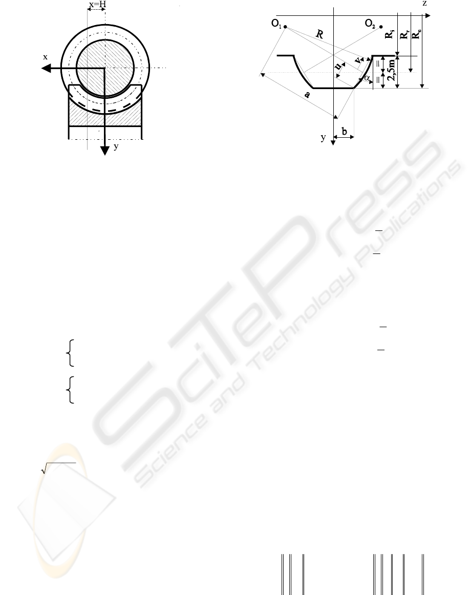
Figure1: Worm-gear drive.
2.1 Worm-Geometry
In order to determine the coordinates of the worm
axial section, we focus on the case of a worm-
gearing with modified profile could ensure, as well
as possible, the generalization of the model from the
geometrical viewpoint. Hence, let the axial section
(x=0) of the worm (Figure 2) with constant pitch,
having a circular arch profile with the centre in O
1
for the right flank and in O
2
for the left flank. The
coordinates of the centre O
1
, respectively O
2
, are
given by the following relations:
Y
O1
=R
e
-u·cosα-a·sinα
Z
O1
=b+u·sinα-a·cosα
(1)
Y
O2
=R
e
-u·cosα-a·sinα
Z
O2
=-b-u·sinα-a·cosα
where: a is a constant parameter;
b=π⋅m/4-1.25⋅m⋅tg α;
p=m/2;
u=1.25⋅m/cosα;
Rau=+
22
is the radius of the circular arc
profile;
R
e
is the tip radius of the worm tooth, all
measured in mm (see Figure 2).
2.1.1 Equations of the Worm Flanks
In accordance with Figure 2, a point of the worm
flank has the following coordinates:
Figure 2: Worm flank geometry.
For the right flank:
X
YY R v
ZZ R v
O
O
=
=+⋅ −+
=+⋅ −+
⎧
⎨
⎪
⎪
⎪
⎩
⎪
⎪
⎪
0
2
2
11
11
;
cos( );
sin( );
π
α
π
α
(2)
For the left flank:
X
YY R v
ZZ R v
O
O
=
=+⋅ −+
=−⋅ −+
⎧
⎨
⎪
⎪
⎪
⎩
⎪
⎪
⎪
0
2
2
22
22
;
cos( );
sin( ).
π
α
π
α
(3)
In the above relations, ν
1
and ν
2
are variable
parameters of the right flank and left flank,
respectively. Generally, the helical motion can be
written by means of two coordinate transformations
corresponding to simple motions, components of the
helical motion: rotation about Oz axis, having
parameter ϕ, and translation on the same axis,
proportional to the rotation angle p⋅ϕ, p being helical
parameter. In this way, the helical motion of the
movable coordinate system XYZ is described by the
matrix equation:
xXa
T
=
⋅+
ω
ϕ
3
(
)
(4)
or
x
y
z
X
Y
Zp
=
−
⋅+
⋅
cos sin
sin cos
ϕϕ
ϕϕ
ϕ
0
0
001
0
0
(5)
where x is the matrix of a point coordinates with
respect to the coordinate system xyz fixed to the
frame, X is the matrix of the same point coordinates
CONTRIBUTION CONCERNING ROBOT ACCURACY USING NUMERICAL MODELING
25
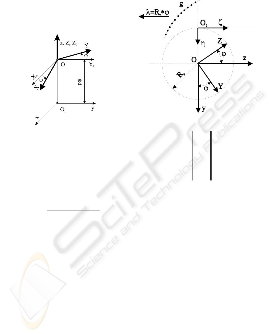
with respect to the movable coordinate system, a is
the matrix of the point O coordinates (the origin of
the movable coordinate system) with respect to the
point O
1
(see Figure 3), and ω
3
(ϕ) is the matrix of
the rotation transformation.
Figure 3: Coordinate system applied for the helical
motion.
Substituting (1), (2) and (3) in (4), we obtain the
parametric equations of the right flank surface and
left flank surface.
Then, crossing these surfaces with the plane
x=H, the curve representing the worm profile
corresponding to the sectional plane takes the form
(for example, the right flank):
Σ
DH
O
O
O
H
YR v
yY R v
zZ R v p
sin
[sin()]
;
[()]cos;
cos( ) ;
ϕ
α
αϕ
αϕ
1
11
111
111
=
−+⋅ −
=+⋅−⋅
=+⋅ −+⋅
⎧
⎨
⎪
⎪
⎩
⎪
⎪
(6)
2.2 Determination of the Worm-Gear
Flank Profile
The worm-gear tooth surface is generated by the
rolling.
We apply the “minimum distance method” on
the algorithm of the discretization in the case of
generation with the rack-bar tool.
First of all, we get the discretization of the
generating curve C
Σ
, which in this case is the worm
profile, represented by the vector (7), where:
y
i
and z
i
are the coordinates of the profile from
the “H” plane, which were determined by (5).
The gear flank generation of the elementary gear
drive is made with the rack-bar tool (see Figure 4).
g
yz
yz
yz
nn
=
11
22
..
..
..
(7)
The rolling condition interpreted in “discrete” way is
the following:
K⋅Δλ=R
r
⋅Δϕ⋅j (8)
Where Δϕ is the angular increment of the rolling. It
is then obvious that for generating a profile with
high accuracy from the technical viewpoint, this
increment has to be enough small.
2.2.1 Generation Motion
The generation motions of the worm-gear flank are:
1) Rotation of centroid, associated to the gear of the
elementary gear drive, with respect to the fixed
coordinate system xyz, described by the matrix
equation
x=ω
1
T
(j⋅Δϕ) X. (9)
In this relation, x is the matrix of the point
coordinates with respect to the fixed coordinate
system, X is the coordinates matrix of the same
point with respect to movable coordinate system
XYZ and ω
1
(ϕ) is matrix of the rotation
transformation about O
x
axis;
2) Translation of the movable coordinate system ξηζ
associated to the rack, with respect to the fixed
Rolling line of
the rack
Figure 4: Worm-gear flank generation.
ICINCO 2008 - International Conference on Informatics in Control, Automation and Robotics
26
coordinate system, described by the equation (a is
the coordinates matrix of the point O
1
, the origin of
the movable coordinate system, with respect to the
point O):
x=ξ+a (10)
with
aR
Rj
r
r
=−
−⋅⋅
0
()Δϕ
. (11)
3) Relative motions
Combining (9) and (10) we obtain that the
motion equation of a point on the generating curve
“g” (Figure 4) from the coordinate system XYZ with
respect to the coordinate system ξηζ is as follows:
ξ=ω
1
T
(j⋅Δϕ) X-a (12)
X=ω
1
T
(j⋅Δϕ)[ξ+a]. (13)
From the last equation, we infer that
⎪
⎪
⎪
⎩
⎪
⎪
⎪
⎨
⎧
⋅
⋅⋅⋅−+⋅⋅−−=
⋅
⋅⋅⋅−+⋅⋅−=
=
).Δcos(j
)]Δ(jR[ζ)Δsin(j)R(ηZ
);Δsin(j
)]Δ(jR[ζ)Δcos(j)R(ηY
ξ;X
rr
rr
ϕ
ϕϕ
ϕ
ϕϕ
(14)
The system of equations (14) represents the
family of generating curves “g” with respect to the
coordinate system of the worm-gear, η and ζ being
the coordinates of the points that are on the
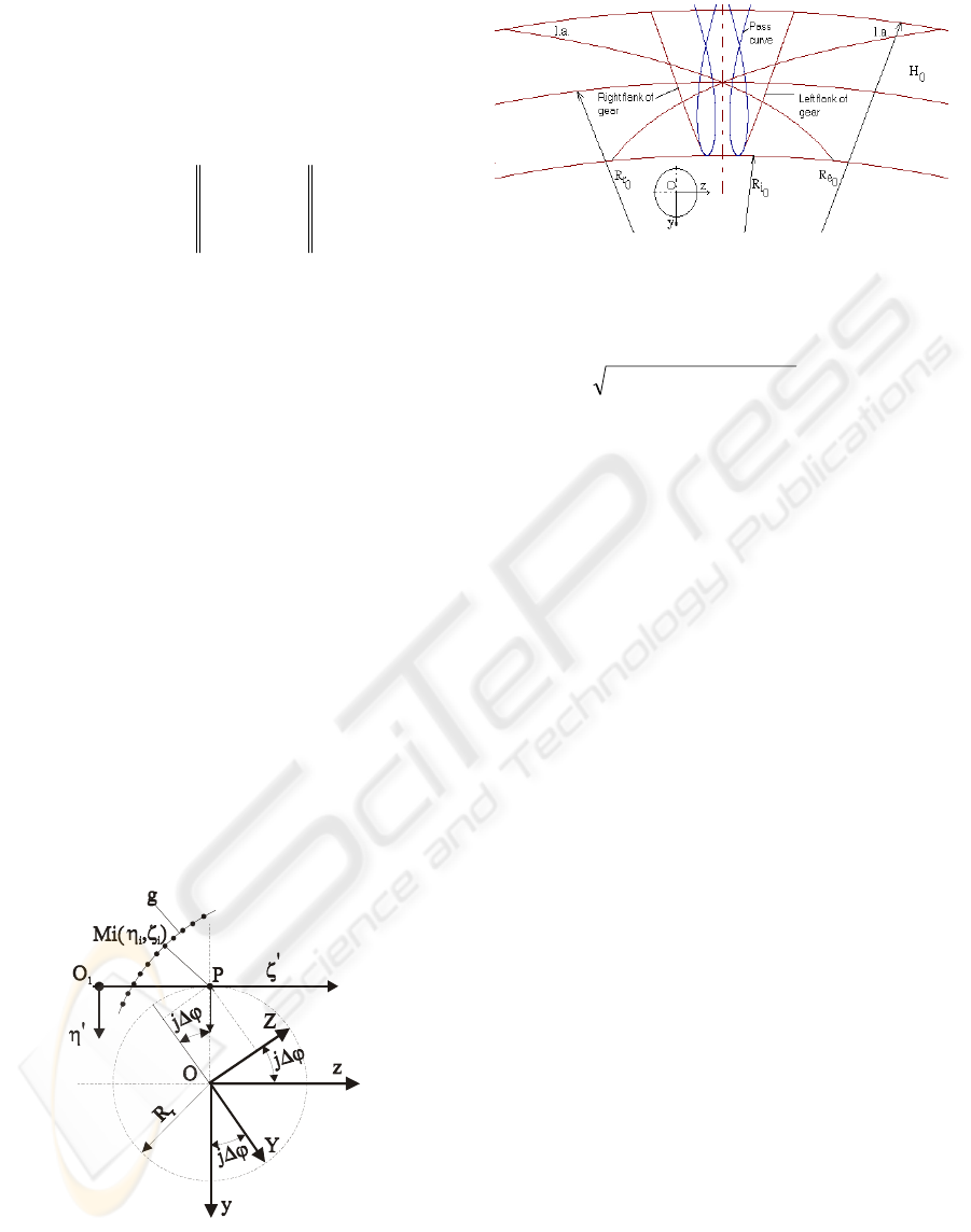
generating curve (Figure 5).
Figure 5: Coordinates of the meshing pole P.
The envelope to the family (14) is what we have
to determine, more precisely, the gear profile (see
Figure 6, flank of gear).
Figure 6: Line of contact (l.a.) in the plane H
0
.
The enveloping condition is given by the
minimum of distance
dYY ZZ
PP
=− +−()()
22
, (15)
where Y
P
and Z
P
(coordinates of the meshing pole)
are:
Y
P
= -R
r
⋅cos(j⋅Δϕ); Z
P
= R
r
⋅sin(j⋅Δϕ). (16)
2.3 Surface of Contact
The surface of contact is defined as locus of the
contact points of the two conjugated surfaces (which
are in enveloping) in the fixed coordinate system
xyz (Figure 4). The parametric equations of the
surface of contact are obtained associating the
enveloping condition to the absolute motion
equation of the worm-gear flank profile. In the
sectional plane x=H, the line of contact is given by:
yY
j
Z
j
zY
j
Z
j
=⋅ ⋅ −⋅ ⋅
=⋅ ⋅ +⋅ ⋅
⎧
⎨
⎩
cos( ) sin( )
sin
(
)
cos
(
)
Δϕ Δϕ ;
Δϕ Δϕ .
(17)
3 WORM-GEARING TOOTH
RIGIDITY
Once the algorithm for the determination of the
contact points, both on the flank height and along
the line of contact, is performed, then it is possible
to evaluate the rigidity of the worm-gearing tooth.
3.1 Bases of Design
The mathematical model is based on the following
assumptions:
The worm-gearing is errors free and the gears are
rigid except the teeth;
Taken into consideration only the bending
produced by the meshing normal force;
CONTRIBUTION CONCERNING ROBOT ACCURACY USING NUMERICAL MODELING
27
Consider that the worm-gearing consists of more
plane-gear drives (pinion-rack drives), named
“elementary gear drives”, that in fact are cross
sections perpendicular to axis of rotation of the
worm-gear (Figure 1);
The tooth of the elementary gear drive is
supposed to be a beam fixed at one end in the body
of gear;
The assembly of the plane-gear drives into the
worm-gear drive was made provided that the teeth of
the elementary gear drives to deform together and
not separately under the same load.
3.2 Computer Program
Our algorithm to evaluate the rigidity of the worm-
gearing tooth is the following (Ghelase, D., 2005):
1) Computation of the rigidity for an elementary
tooth;
2) Computation of the rigidity for a pair of
elementary teeth;
3) Computation of the rigidity for an elementary
gearing tooth (pinion-rack drive);
4) Computation of the rigidity for the worm-
gearing tooth.
0
200
400
600
800
1000
1200
1400
1600
1800
2000
-69
-46
-23
0
23
46
69
92
115
138
161
184
207
230
253
276
Rolling angular parameter
Rigidity [KN/mm]
Figure 7: Rigidity of the worm-gearing tooth.
By means of the numerical modelling, these
steps will be added to the computer program used
for the study of the worm-gearing tooth geometry,
finally providing the instrument for the
determination of the worm-gearing tooth rigidity.
The computation diagram of rigidity of worm-
gearing tooth can be seen in Figure 7.
The cvasisinusoidal zone of the curve from
Figure 7 repeats periodically, because it represents
the rigidity during the meshing when the all plane-
gear drives are involved in the meshing. Thus, if the
input and output rigidities are eliminated, being less
importing for our study, we get the elasticity
characteristic of the worm-gearing tooth.
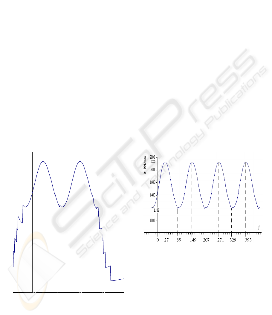
3.3 Elasticity Characteristic
The elasticity characteristic represents the variation
of rigidity of the worm-gearing tooth depending on
the rolling angle (j·Δφ), where “j” is the rolling
angular parameter (Ghelase, D., Tomulescu, L.,
2003). It is cvasisinusoidal curve with the high
jumps when a tooth binds or recesses (Figure 8).
The investigation of the elasticity characteristic
is very important for the study of an elastic system,
such as: gearing, linkage. Hence, the introduction of
this concept contributes to the completion of the
used gearing study and it leads to increase of the
gearing tooth rigidity.
Figure 8:
Elasticity characteristic of the worm-gearing
tooth.
3.4 Influence of Geometrical
Parameters
The influence of the geometrical parameters on the
rigidity was obtained by means of the computerized
simulation (Ghelase, D., 2003). It was applied to 150
worm-gear drives and we can present the following
conclusions:
1. The rigidity of worm-gearing tooth increases if
diametral quotient q increases and radius of profile
curvature R increases (Ghelase, D., 2003).
ICINCO 2008 - International Conference on Informatics in Control, Automation and Robotics
28
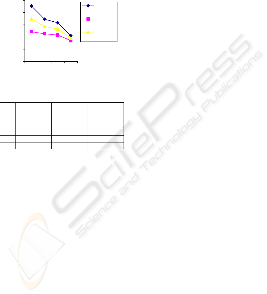
2. The rigidity of worm-gearing tooth reduces if
profile angle α increases (Ghelase, D., 2003) and
number of the gear teeth z
2
increases (Figure 9,
Table 1).
0
500
1000
1500
2000
2500
53 80 90 169
z
2
Rigidity kN/mm
Maximum
Rigidity
Minimum
Rigidity
Medium
Rigidity
Figure 9: Rigidity depending on number of gear teeth z
2
.
Table 1: Influence of number of gear teeth on rigidity.
z
2
Maximum
Rigidity
[kN/mm]
Minimum
Rigidity
[kN/mm]
Medium
Rigidity
[kN/mm]
53 2267.385 1215.140 1741.262
80 1727.633 1132.201 1429.917
90 1581.896 1079.696 1330.796
169 1055.990 853.826 954.908
4 CONCLUSIONS
Finally, we can draw the following conclusions:
1) A method to evaluate the rigidity of worm-
gearing tooth was developed;
2) The proposed approach may be applied for
any types of cylindrical worm-gearing and for spur
gearing and bevel gearing. These mechanisms are in
the structure of robot and by them rigidity depends
the kinematical accuracy of robot;
3) The introduction of “elasticity characteristic”
concept contributes to the completion of study for
the used mechanisms;
4) The developed computer program enables to
obtain numerical solutions and graphic illustration;
5) The numerical method, proposed and analyzed
in this paper, affords the geometry optimization and
the study of the meshing for various geometrical
parameters of the worm-gearing, being in fact a
simulation of meshing;
6) Moreover, we can determine the parameters
which influence the improvement of rigidity for
worm-gearing tooth and the increase of accuracy of
robot linkages.
REFERENCES
Ghelase, D., Daschievici, L., 2006. Computerized Design-
Generation of the Worm-Gear Flank.
The Archive of
Mechanical Engineering– Polish Academy of Sciences
Committee of Machine Design , 2, 165-178.
Ghelase, D., Gratie, L., 2005. Numerical Computation
Rigidity of Worm-Gearing Tooth with Circulare
Profile. In
IEEE ICIT2005, International Conference
on Industrial Techology.
City University of Hong
Kong.
Ghelase, D., Tomulescu, L., 2003. Computerized
Determination of the Elasticity of the Worm-Gearing
Tooth for Machine-Tools and Robots. In
Machine-
Building and Technosphere of the XXI Century,
International Science and Engineering Conference.
Donetsk National Technical University.
Ghelase, D., 2003. Influence of the Geometrical
Parameters on Rigidity of the Worm-Gearing Tooth.
The Annals of “Dunarea de Jos” University of Galati,
Fascicle XIV,
45-48.
CONTRIBUTION CONCERNING ROBOT ACCURACY USING NUMERICAL MODELING
29
