DISCRETE-TIME ADAPTIVE REPETITIVE CONTROL
Internal Model Approach
Andrzej Krolikowski and Dariusz Horla
Poznan University of Technology, Institute of Control and Information Engineering
Division of Control and Robotics, ul. Piotrowo 3a, 60-965, Poland
Keywords:
Discrete-time systems, IMC structure, Adaptive repetitive control.
Abstract:
Repetitive control is known as one of the most effective methods to reduce repetitive errors with a known
period in various practical control systems performing repetitive tasks. The application of Internal Model
Control (IMC) structure for repetitive control is introduced. Two IMC-based repetitive control configurations
are proposed together with their adaptive versions. A comparative simulation study is carried out for the model
of a first link of the robot.
1 INTRODUCTION
Many computer-controlled control systems perform
repetitive (periodic) tasks thus being subjected to
repetitive as well as nonrepetitive disturbances. Re-
jecting of periodic disturbances or tracking a periodic
reference signal can be considered as the original aim
of the repetitive controller. In last years much effort
has been devoted to the development of discrete-time
repetitive control systems which may be considered
to be very powerful tools to regulate the repetitive er-
rors whose fundamental frequencies are priori known
(Hillerström and Walgama, 1996; Chang et al., 1995;
Kempf et al., 1993; Hu and Yu, 1996). The case of un-
certain period time is analyzed in (Steinbuch, 2002).
Usually, the repetitive errors containing only one fun-
damental frequency and its harmonics are taken for
consideration. A discrete-time repetitive controller
for odd harmonic reference and disturbance signals is
proposed in (Griñó and Costa-Castelló, 2005). This
type of signals appear for example in power electron-
ics systems. Usually, the period of repetitive signals
is assumed to be known. In (Steinbuch, 2002), a new
structure for repetitive control is proposed which is
robust for changes in period-time. The problem of
tracking arbitrary periodic reference signals is dis-
cussed in (Ledwich and Bolton, 1993), where the
compensator design is proposed to give zero steady-
state error. The robustness issues of repetitive con-
trol are for example examined in (Chang et al., 1995;
Hu and Yu, 1996; Tenney and Tomizuka, 1996). The
problem of adaptiverepetitivecontrol is not much dis-
cussed in the literature.
In this paper, two structures of the adaptive repeti-
tive IMC system are presented and simulated using
the model of one link of the robot.
2 THE INTERNAL MODEL
PRINCIPLE
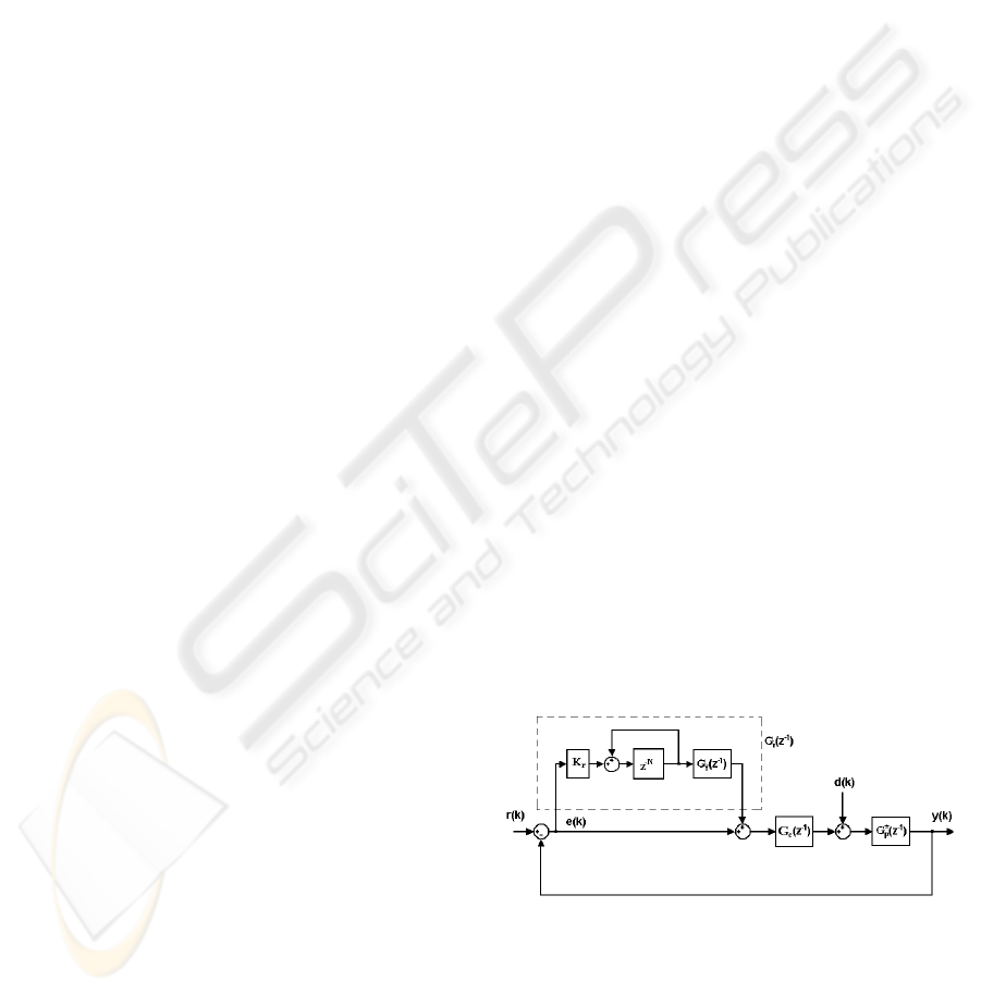
A block diagram of the conventional discrete-time
repetitive control system based on the Internal Model
Principle (IMP) for a single fundamental frequency of
repetitive errors is shown in Fig.1.
Figure 1: IMP-based repetitive control system.
In this block diagram r(k) and d(k) represent
the unknown periodic reference and disturbance with
known period, respectively. Typically, the disturbance
is assumed to have one fundamental frequency f
o
and
higher harmonics. The gain K
r
is an adjustable pa-
rameter of the repetitive controller G
r
(z
−1
).
90
Krolikowski A. and Horla D. (2008).
DISCRETE-TIME ADAPTIVE REPETITIVE CONTROL - Internal Model Approach.
In Proceedings of the Fifth International Conference on Informatics in Control, Automation and Robotics - SPSMC, pages 90-95
DOI: 10.5220/0001479700900095
Copyright
c
SciTePress
The IMP implies a use of the repetitive signal gener-
ator which is a N step delay chain with positive feed-
back around it (Hillerström and Walgama, 1996) hav-
ing the transfer function
G
im
(z
−1
) =
z
−N
1− z
−N
(1)
This generator represents simply the model of a pe-
riodic disturbance. If T
s
denotes the sampling period
then NT
s
is chosen to be equal to the period of the
fundamental component of the repetitive errors, i.e.
NT
s
= T
o
=
1
f
o
so N =
T
o
T
s
. A harmonic signal has only
one component at
2Πk
NT
s
rad s
−1
for k = 1, 2, ···.
Let the plant be given by the transfer function
G
∗
p
(z
−1
). It is known (Kempf et al., 1993) that for the
repetitive control system design a parametric model
of the plant is required. The nominal plant is charac-
terized by the transfer function
G
p
(z
−1
) = z
−d
B(z
−1
)
A(z
−1
)
(2)
with B(z
−1
) = b
1
z
−1
+ ·· · + b
nb
z
−nb
, A(z
−1
) = 1 +
a
1
z
−1
+ · ·· + a
na
z
−na
and d ≥ 0.
A nominal feedback controller G
c
(z
−1
), typically a
lag-lead compensator or PD controller is designed
so that for the nominal open-loop transfer function
G
o
(z
−1
) = G
c
(z
−1
)G
p
(z
−1
), the nominal closed-loop
transfer function
G(z
−1
) =
G
o
(z
−1
)
1+ G
o
(z
−1
)
(3)
is asymptotically stable and minimumphase. To as-
sure the stability of the control system with repetitive
controller the filter G
f
(z
−1
) such that
G
f
(z
−1
)G(z
−1
) = 1 (4)
is usually introduced (Chang et al., 1995; Kempf
et al., 1993; Chang et al., 1998).
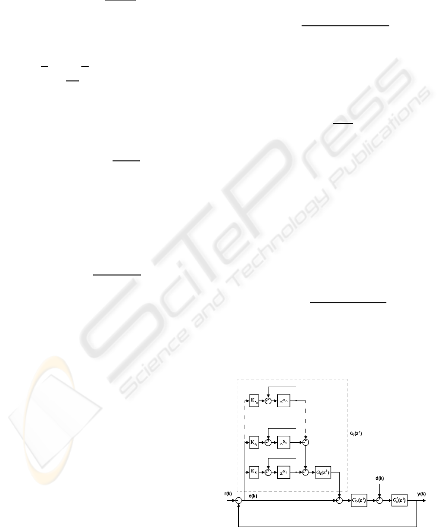
3 THE MULTIPLE REPETITIVE
CONTROL SYSTEM
The purpose of the multiple repetitive controller is to
regulate multiple repetitive errors which contain mul-
tiple dominant fundamental frequencies and their har-
monics (Chang et al., 1998). The multiple repetitive
discrete-time control system is depicted in Fig.2. It is
worthy to note that all repetitive control systems can
be augmented by multiple repetitive loops.
Consider again the unmodelled dynamics in the
form of a multiplicative modelling uncertainty given
by G
∗
(z
−1
) = G(z
−1
)[1 + ∆(z
−1
)]. Then from (4), a
relationship between G
f
(z
−1
) and G
∗
(z
−1
) can be ob-
tained in terms of modelling uncertainty
G
f
(z
−1
)G
∗
(z
−1
) = 1+ ∆(z
−1
)] (5)
From (3),(4) and (5), a modelling uncertainty can be
derived as
∆(z
−1
) =
G
∗
p
(z
−1
) − G
p
(z
−1
)
G
p
(z
−1
)(1+ G
∗
o
(z
−1
))
(6)
where G
∗
o
(z
−1
) = G
c
(z
−1
)G
∗
p
(z
−1
).
Assuming that |∆(z
−1
)| ≤ ε for each z such that
|z| ≥ 1, the robust stability can be demonstrated
(Chang et al., 1998) provided that the gains K
ri
sat-
isfy the condition
n
∑
i=1
K
ri
<
2
1+ ε
. (7)
4 THE INTERNAL MODEL
CONTROL STRUCTURE
4.1 The Main IMC Configuration
The discrete-time IMC (Internal Model Control) sys-
tem structure is shown in Fig.3. This structure is
a counterpart of the continuous-time IMC controller
given in (Datta, 1998). It is known that every stabiliz-
ing controller G
c
(z
−1
) is given by
G
c
(z
−1
) =
Q(z
−1
)
1− G
p
(z
−1
)Q(z
−1
)
(8)
where Q(z
−1
) varies over the set of all stable ratio-
nal transfer functions. This structure may also yield
a stable closed-loop performance for unstable plant
Figure 2: Multiple repetitive control system.
DISCRETE-TIME ADAPTIVE REPETITIVE CONTROL - Internal Model Approach
91
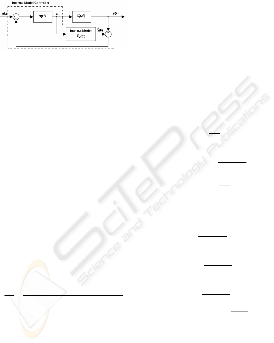
Figure 3: IMC structure.
provided that a plant model
ˆ
G
p
(z
−1
) is stable, how-
ever in this case Q(z
−1
) must not only be stable but
must also satisfy certain constraints imposed by un-
stable poles of the plant.
Suppose that the (possibly proper)
ˆ
G
p
(z
−1
), Q(z
−1
) are stable so that the IMC structure
is stable for
ˆ
G
p
(z
−1
) = G
∗
p
(z
−1
). Let the uncertainty
modelling have the following multiplicative form
G
∗
p
(z
−1
) =
ˆ
G
p
(z
−1
)[1+ ∆
p
(z
−1
)] (9)
where ∆
p
(z
−1
) is stable strictly proper uncertainty.
From the IMC structure (Fig.3) the following equa-
tion can be derived
u(k) = −
ˆ
G
p
(z
−1
)Q(z
−1
)∆
p
(z
−1
)u(k) + Q(z
−1
)r(k)
(10)
so
||u(k)||
2
≤ ||
ˆ
G
p
(z
−1
)Q(z
−1
)∆
p
(z
−1
)||
∞
||u(k)||
2
+
+||Q(z
−1
)||
∞
||r(k)||
2
(11)
This shows that if
||
ˆ
G
p
(z
−1
)Q(z
−1
)∆
p
(z
−1
)||
∞
< 1 (12)
then
||u(k)||
2
≤ [1− ||
ˆ
G
p
(z
−1
)Q(z
−1
)∆
p
(z
−1
)||
∞
]
−1
×
×||Q(z
−1
)||
∞
||r(k)||
2
(13)
so the condition (12) gives the sufficient condition
for L
2
stability, thus the IMC structure is robust with
respect to modelling errors in the plant. Note that the
closed-loop transfer function is
y(z)
r(z)
=
ˆ
G
p
(z
−1
)Q(z
−1
)∆
p
(z
−1
) +
ˆ
G
p
(z
−1
)Q(z
−1
)
1+
ˆ
G
p
(z
−1
)Q(z
−1
)∆
p
(z
−1
)
(14)
For similar approach in continuous-time IMC struc-
ture see (Datta, 1998).
4.2 The Pole-placement IMC
Configuration
The standard RST controller has a form
R(z
−1
)u(k) = −S(z
−1
)y(k) + T(z
−1
)r(k + d + 1)
(15)
and is the solution of
A(z
−1
)R(z
−1
) + z
−d
B(z
−1
)S(z
−1
) = A(z
−1
)P(z
−1
)
(16)
where P(z
−1
) is the stable polynomial the roots of
which are assumed to be the closed-loop poles. The
above equation implies that
S(z
−1
) = A(z
−1
)S
′
(z
−1
), (17)
i.e.(16) is replaced by
R(z
−1
) + z
−d
B(z
−1
)S
′
(z
−1
) = P(z
−1
) (18)
and this allows the controller to be characterized by
R(z
−1
) = P(z
−1
) − z
−d
B(z
−1
)S
′
(z
−1
). (19)
Polynomial S
′
(z
−1
) is assumed to be stable. For ex-
ample, if R(z
−1
) contains an integrator then
S
′
(1) =
P(1)
B(1)
(20)
yielding
R(z
−1
) = P(z
−1
) − z
−d
B(z
−1
)P(1)
B(1)
(21)
and
S(z
−1
) = A(z
−1
)
P(1)
B(1)
(22)
Using the controller equation (15) and (18) one ob-
tains
P(z
−1
)B(1)
A(z
−1
)P(1)
u(k) = −[y(k) − z
−d
B(z
−1
)
A(z
−1
)
u(k)] +
+
T(z
−1
)B(1)
A(z
−1
)P(1)
r(k + d + 1) (23)
which is the IMC scheme as shown in Fig.4 where
G
T
(z
−1
) =
T(z
−1
)B(1)
A(z
−1
)P(1)
. (24)
and using the notation from Fig.3
Q(z
−1
) =
A(z
−1
)P(1)
P(z
−1
)B(1)
. (25)
It is easy to see that taking T(z
−1
) =
P(1)A(1)
B(1)
guaran-
tees the zero steady-state error in the case of perfect
matching.
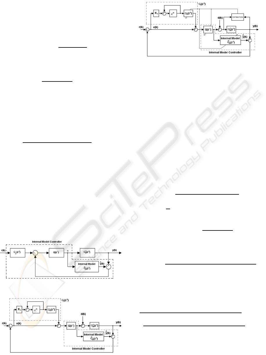
4.3 The Repetitive IMC Configuration
The proposed repetitive IMC system structure is rep-
resented in Fig.5. This is a combination of the IMC
structure (Figs.3,4) and the standard repetitive con-
troller (or multiple repetitive controller). The aim of
ICINCO 2008 - International Conference on Informatics in Control, Automation and Robotics
92
this control system is reject the repetitive errors by the
repetitive controller and to improve the robustness by
a proper choice of Q(z
−1
.
From (3), (4), (9) and (13) the following rela-
tion between uncertainties ∆
p
(z
−1
) and ∆(z
−1
) can be
found
∆(z
−1
) =
∆
p
(z
−1
)
1+ G
∗
o
(z
−1
)
. (26)
Taking into account that |∆(z
−1
)| ≤ ε as in (6) the
following condition can be derived
|
∆
µ
(z
−1
)
1+ G
∗
o
(z
−1
))
| ≤ ε (27)
This means that under this condition the robust sta-
bility of the repetitive IMC structure will be assured
if additionally the uncertainty ∆(z
−1
) is stable. The
inequality (27) can not practically be checked out be-
cause G
∗
o
(z
−1
) is not known, however using (8) and
(9) the inequality |∆(z
−1
)| ≤ ε takes a form
|
∆
p
(z
−1
)(1− G
p
(z
−1
)Q(z
−1
))
1+ G
p
(z
−1
)Q(z
−1
)∆
p
(z
−1
)
| ≤ ε (28)
so the (multiple) repetitive IMC system is robustly
stable if the uncertainty ∆
p
(z
−1
) is such that the above
condition is fulfilled.
4.4 The Adaptive Repetitive IMC
Structure
The proposed adaptive repetitive IMC system struc-
ture is represented in Fig.6, where the parameter esti-
mation is realized using the standard recursive least-
squares algorithm. The adaptation is realized in an
Figure 4: Pole-placement IMC structure.
Figure 5: Repetitive IMC structure.
Figure 6: Adaptive repetitive IMC structure.
indirect way, i.e. the model parameters are first esti-
mated, and subsequently the obtained parameter es-
timates
ˆ
θ(k) = ( ˆa
1
(k), . . . , ˆa
na
(k),
ˆ
b
1
(k), . . . ,
ˆ
b
nb
(k))
T
are used for tuning the parameters of both repetitive
and internal model controllers.
5 SIMULATIONS
Often robotic manipulators are required to execute
repetitive tasks. Then the desired trajectory to be fol-
lowed by the manipulator is bounded and periodic
with known period. Below a first link of the Adep-
tOne robot (Tenney and Tomizuka, 1996) is taken as
an example for simulations. The link considered as a
plant is approximated by the nominal ARX model
G
p
(z
−1
) =
0.000242z
−1
1− 1.9788z
−1
+ 0.9789z
−2
(29)
obtained at
1
T
s
= 1kHz sampling rate. The nominal
compensator has a form of PD-type
G
c
(z
−1
) = 119.5
1− 0.925z
−1
1− 0.65z
−1
. (30)
The main IMC repetitive controller has been
tested for
Q(z
−1
) =
119.5− 347z
−1
+ 335.7z
−2
− 108.2z
−3
1− 2.6z
−1
+ 2.238z
−2
− 0.6363z
−3
(31)
that has been obtained according to (8) for a stable
plant model (29). In turn, the filter G
f
(z
−1
) was de-
rived according to (4) as
G
f
(z
−1
) =
1− 4.55z
−1
+ 8.278z
−2
− 7.529z
−3
0.02892z
−1
− 0.08397z
−2
+ 0.08124z
−3
− 0.02619z
−4
+
3.424z
−4
− 0.6229z
−5
0.02892z
−1
− 0.08397z
−2
+ 0.08124z
−3
− 0.02619z
−4
. (32)
The disturbance d(k) with amplitude of 5 units con-
tains the fundamental and harmonic frequencies of
f
o1
= 5Hz (10Hz, 15Hz), f
o2
= 7Hz (14Hz, 21Hz),
f
o3
= 9Hz (18Hz,27Hz) thus N
1
= 200, N
2
= 143,
DISCRETE-TIME ADAPTIVE REPETITIVE CONTROL - Internal Model Approach
93
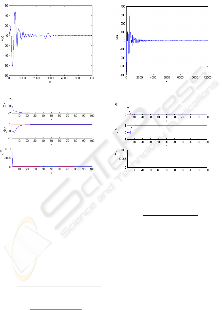
Figure 7: Adaptive repetitive IMC, disturbance attenuation.
Figure 8: Adaptive repetitive IMC, parameter estimates.
N
3
= 111 with K
r1
= K
r2
= K
r3
= 0.5. Additionally,
a pulse disturbance d
p
with amplitude of 15 units is
also inserted to the input of the plant.
The initial conditions for parameter estimates and
covariance matrix in the recursive least squares al-
gorithm were taken as
ˆ
θ(0) = (0.01, 0.01, 0.01)
T
and
P(0) = 100I.
The performance of adaptive multiple repetitive
IMC control system given in Fig.7 shows the effect of
disturbance attenuation. The corresponding parame-
ter estimates are shown in Fig.8.
Finally, the adaptive pole-placement IMC structure
was combined with multiple repetitive controller. For
the polynomial P(z
−1
) = 1−1.8z
−1
+ 0.9z
−2
one ob-
tains from (25)
Q(z
−1
) =
0.1− 0.1979z
−1
+ 0.09789z
−2
0.000242− 0.0004356z
−1
+ 0.0002178z
−2
,
(33)
and from (24)
G
T
(z
−1
) =
0.0001
1− 1.979z
−1
+ 0.9789z
−2
. (34)
Figure 9: Adaptive repetitive pole-placement IMC.
Figure 10: Adaptive repetitive pole-placement IMC.
The filter G
f
(z
−1
) was derived again from (4), how-
ever in this case the transfer function G(z
−1
) is
G(z
−1
) =
G
T
(z
−1
)Q(z
−1
)G
p
(z
−1
)
1+ G
T
(z
−1
)Q(z
−1
)G
p
(z
−1
)
. (35)
The error signal is shown in Fig.9, and the corre-
sponding parameter estimates are shown in Fig.10 for
multiple harmonic disturbance attenuation.
6 CONCLUSIONS
Two structures of IMC repetitive control system are
examined and their adaptive versions are simulated
taking the first link of an AdeptOne robot as the ex-
ample. The proposed control structures can be en-
larged by the multiple repetitive controller. The adap-
tive loop included into the IMC repetitive control sys-
tem reduces the level of parametric uncertainty thus
improves the quality of disturbance attenuation. In
ICINCO 2008 - International Conference on Informatics in Control, Automation and Robotics
94

this way the proposed configurations can be consid-
ered as the robust adaptive ones.
REFERENCES
Chang, W., Suh, I., and Kim, T. (1995). Analysis and de-
sign of two types of digital repetitive control systems.
Automatica, 31(5):741–746.
Chang, W., Suh, I., and Oh, J.-H. (1998). Synthesis
and analysis of digital multiple repetitive control sys-
tems. In Proceedings of the ACC, pages 2687–2691,
Philadelphia.
Datta, A. (1998). Adaptive internal model control.
Springer.
Griñó, R. and Costa-Castelló, R. (2005). Digital repeti-
tive plug-in controller for odd-harmonic periodic ref-
erences and disturbances. Automatica, 41:153–157.
Hillerström, G. and Walgama, K. (1996). Repetitive control
theory and applications - a survey. In Proceedings of
the 13th IFAC World Congress, pages CD–ROM, San
Francisco.
Hu, J. and Yu, S.-H. (1996). Optimal repetitive control
system design using mixed time and frequency do-
main criteria. In Proceedings of the 13th IFAC World
Congress, pages CD–ROM, San Francisco.
Kempf, C., Messner, W., Tomizuka, M., and Horowitz, R.
(1993). Comparison of four discrete-time repetitive
control algorithms. IEEE Control Systems, 13(6):48–
54.
Ledwich, G. and Bolton, A. (1993). Repetitive and periodic
controller design. IEEE Proceedings-D, 140(1):19–
24.
Steinbuch, M. (2002). Repetitive control for systems with
uncertain period time. Automatica, 38:2103–2109.
Tenney, J. and Tomizuka, M. (1996). Effects of non-
periodic disturbances on repetitive control systems. In
Proceedings of the 13th IFAC World Congress, pages
CD–ROM, San Francisco.
DISCRETE-TIME ADAPTIVE REPETITIVE CONTROL - Internal Model Approach
95
