
DESIGN AND BALANCING CONTROL OF AIT LEG
EXOSKELETON-I (ALEX-I)
Narong Aphiratsakun, Kittipat Chirungsarpsook and Manukid Parnichkun
Asian Institute of Technology, P.O.Box 4, Klong Luang, Pathumthanee, 12120, Thailand
Keywords: ALEX-I, Exoskeleton, robot suit, balancing control, mechanical design.
Abstract: This paper is focused on the design of mechanical hardware, controller architectures, and analysis of
balancing control at the Asian Institute of Technology Leg EXoskeleton-I (ALEX-I). ALEX-I has 12 DOF
(6 DOF for each leg: 3 at the Hip, 1 at the knee and 2 at the ankle), controlled by 12 DC motors. The main
objective of the research is to assist patients who suffer from the paraplegia and immobility due to the loss
of lower limbs. ALEX-I’s parts and assembly are designed on CAD software, SolidWorks, exported to
MATLAB simulation environment, and observed using 3D VRML script interpreter to investigate balancing
postures of the exoskeleton. The simulation model is proven to be accurate by comparing the resulting
kinematics characteristics with the results from Corke’s MATLAB Robotics Toolbox (Corke, 1996). PC104
is employed as the main (master) processing unit for calculation of the balanced gait motion corresponding
to feedback signals from the force sensors mounted at the two feet plates, whereas ARM7’s are used for the
low-level (slave) control of the angular position of all joints. The balanced posture set-points (joint
trajectories) under the Center of Mass (CM) Criterion are generated in the simulation before testing on the
real mechanical parts is implemented to avoid damaging the system.
1 INTRODUCTION
Our society nowadays has many elders and patients
that have difficulties in their locomotion. All of
these patients need to sit, stand, walk, and perform
other activities to fulfil their daily tasks. These
people need assistance from either the nursing
personnel or assistive devices such as walkers or
wheelchairs. Our exoskeleton is intended to work as
an intelligent assistive device that would help
eliminating the difficulties and risks during the
locomotion of the wearer. For this purpose, the
exoskeleton has to be able to balance itself, carry the
wearer, and walk even if the lower part of the patient
is completely paralyzed. In addition to improving
the quality of many lives, the developed exoskeleton
can also serve as a tool used to imitate and integrate
human natural blueprints.
Exoskeleton systems also find their applications
in other various fields that draw a lot of interests
from many robotics researchers who want to imitate
the perfectly-designed and sophisticated
biomechanics and human anthropometries. Some of
the successful stories are HAL (Kawamoto, Kanbe,
Lee and Sankai, 2002 and 2003), BLEEX (Chu,
Kazerooni, Zoss, Racine, Huang and Steger, 2005),
and Sarcos (Guizzo and Goldstein, 2005)
exoskeletons, which are designed for power
enhancing and military missions respectively. HAL-
3 was developed by the research team of Tsukuba in
Japan. It was designed to help the elders in
performing their daily activities such as walking,
sitting, and standing. The latest model, HAL-5, is
the whole-body suit unit, which is suitable for either
the left or the right side paraplegic patient. BLEEX
developed by the University of California, Berkeley,
and Sarcos developed at Sarcos Research Corp. in
Salt Lake City implemented the hydraulic-actuated
exoskeletons as they are focusing on the power-
enhanced legs for the application of carrying heavy
loads in the difficult terrains.
Asian Institute of Technology Leg EXoskeleton-
I or known as ALEX-I is developed with the aim to
carry with it both the external loads and the pilot (or
the wearer). The exoskeleton has to be able to walk
on its own. Building up the robot and physically
testing it by means of trial-and-error could result in
damaging the robot links and fragile electronics
devices. Hence, we have to model the exoskeleton
robot to conduct the experiments in the both real
world and simulated environments. The simulation
model of ALEX-I has shown promising results
151
Aphiratsakun N., Chirungsarpsook K. and Parnichkun M. (2008).
DESIGN AND BALANCING CONTROL OF AIT LEG EXOSKELETON-I (ALEX-I).
In Proceedings of the Fifth International Conference on Informatics in Control, Automation and Robotics - RA, pages 151-158
DOI: 10.5220/0001480401510158
Copyright
c
SciTePress
through the modelling with MATLAB’s
SimMechanics library. Consequently, precise gait
pattern generation can be investigated based on the
kinematics information of all moving bodies. This
simulation model can serve as the framework for
development of the whole-body exoskeleton and all
types of biped robots, which will be developed in the
future at AIT.
This paper describes the analysis of the
architecture layout of the ALEX-I system in both
software and mechanical hardware. The mechanical
properties and controllers layout of the ALEX-I will
be explained in the next 2 sections. The simulation
model of the exoskeleton, its the interpretation of
experimental result in 3D virtual reality (VR)
environment, as well as the example of gait pattern
generation of one-step gait motion will be discussed
in section 4.
2 MECHANICAL DESIGN
Our previous work (Aphiratsakun and Parnichkun,
2007) reveals the required specification of the 12
actuators through the required torque calculations of
all the joints. The range of motion of the joints
determined in the previous work is refined to
disregard the range that will never be employed in
the real physical implementation, and the resulting
range of motion of all DOF is shown in Table 1.
The ALEX-I has 12 DOF (6 DOF for each leg: 3
at the Hip, 1 at the knee and 2 at the ankle),
controlled by 12 DC motors. Each motor is coupled
with a 1:100 gearhead and equipped with a 1024-
pulse incremental encoder as a feedback sensor. The
Scooter DC motors and Bonfiglioli Gearhead model
VF44P63B14 are selected in this work to conform to
the required flexibility in the mounting structures,
shapes, and weights. Table 2 gives specification of
the motors and the gearheads mounted on each joint.
Obviously, the torques offered by the gearheads in
each joint are in comply with the torque
requirements revealed in (Chu, Kazerooni and Zoss,
2005).
Table 1: Range of motion of each joint.
Joint Axis Range of rotation
(degree)
X (pitch) -90<θ<90
Y (yaw) -35<θ<35
Hip
Z (roll) -15<θ<15
Knee X (pitch) 0<θ<90
X (pitch) -45<θ<45 Ankle
Z (roll) -20<θ<20
Table 2: Specification of the motors coupled with 1:100
gearhead at each joint.
Motors
Joints the motors
mounted on
RPM ;
Rad/s
Torque
[Nm]
250 W Hip (yaw) 95
350 W
Hip (roll),
Ankle (roll)
134
500 W
Hip (pitch),
Knee (pitch),
Ankle (pitch)
25 ; 2.62
191
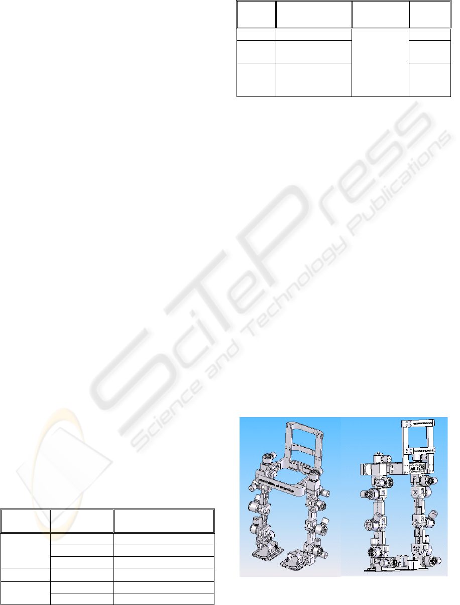
The lower limb exoskeleton mechanical parts are
designed with a CAD Application, SolidWorks, as
shown in Figure 1. The anthropometric
considerations and other design parameters are
discussed in (Aphiratsakun and Parnichkun, 2007).
This CAD assembly can be imported to MATLAB
development environment, which will be used to
analyze for the balanced gait motion through the
simulation model. The simulation model will be
revisited in section 4.
With the CAD design, aluminum 5083 with the
density of 2657.27 Kg/m
3
is mainly used for the
frame structure. The front and back views of the
fabricated prototype is shown in Figure 2. The
weight of the ALEX-I is measured to be 117.5 Kg
excluding the weight of the bag pack.
Force sensors or load cells are used to measure
the forces exerted by the body. Futek LLB400 load
cell, which can measure up to 500 lb (2224 N) of
force, is chosen in the implementation. Four of these
sensors are placed between two plates of the ALEX-
I’s feet. INA126 micro power instrumentation
amplifier is used as the amplifier for the load cell.
The designed layout of the load cell and its amplifier
circuit is shown in Figure 3. From the force reading
from the load cells, the center of mass (CM) position
could be calculated.
Figure 1: Prototype design of exoskeleton frame (lower
part) (a) front view and (b) back view.
ICINCO 2008 - International Conference on Informatics in Control, Automation and Robotics
152
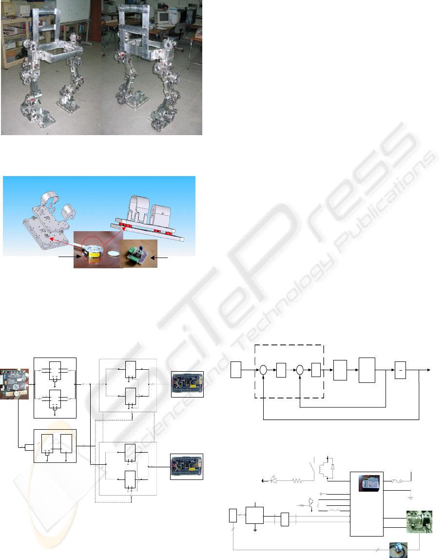
Figure 2: Front and back views of the ALEX-I mechanical
frame.
Amplifier
Circuit
Load Cell
ALEX-I’s feet
Figure 3: Load cells arrangement.
3 CONTROLLER
ARCHITECTURE
16
8
74LS373
(1)
D
1-8
Q
1-8
O/P
Control
G
8
8
74LS373
(2)
D
1-8
Q
1-8
O/P
Control
G
8
16
ARM (1)
16
74LS154 (1)
System 1
ARM (12)
System 12
12
4
74LS373
(1), (2)…..(12)
5
Buffer
1A
2A
1Y
2Y
74LS244
4
4
8 8
1G 2G
PC104
1A
2A
1Y
2Y
74LS244
4
4
8 8
1G 2G
16
74LS154
4IN
ABCD
OUT
74LS244
1A
1Y
2A
2Y G
2
G
1
1G
2G
Chip Select
8
74LS373
(1)
D
1-8
Q
1-8
O/P
Control
G
8
8
74LS373
(2)
D
1-8
Q
1-8
O/P
Control
G
8
16
16
74LS154 (12)
Latch
Latch
Figure 4: Overview of High and Low level controllers’
architecture.
The data of gait analysis from the simulation is used
as the input for positional control of the motors,
which will eventually make ALEX-I walk in the
desired motion. In this work PC104 and ARM7
LPC2138 are used as the high and low level
controllers respectively. The overview of the
controllers’ layout is shown in Figure 4. The twelve
set-points data for the joints’ trajectories, which are
sent from PC104, are stored in the latching circuit to
eliminate the lag time that might be incurred from
serial communication. Chip selecting circuit is then
used to address each slave-controller with its proper
set point. Putting these set-points data in parallel
manner allows low-level controller to acquire the
data without delay.
3.1 Joint Controller: ARM7 LPC2138
Microcontroller
The joint controller block set is shown in Figure 5.
The twelve sets of 16-bits set points command are
sent from PC104, which configures the required
motion balancing tasks for the whole system, as the
input to the low-level close-loops that comprise 2
closed loops (P and PD) for each control block:
speed and position loops. 10 Bits, 1024 pulses/rev
Koyo TRD-S1024V series incremental encoder is
used as a feedback sensor at each joint. LS7366 by
LSI, is used to obtain the quadrature A/B of the
incremental encoder signal. This IC communicates
through SPI with ARM7 processor and increases the
quadrature counting up to four times. It increases the
resolution of the encoders to 4096 pulses/rev. Axor
MicrospeedPlus is chosen as the servo driver and
interfaced between ARM7 as shown in Figure 6.
Mo t o r
+
Gearhead
1
s
-
+
-
+
Mot or
Dr i v er
PC10 4
Set point
joint di stance
P
PD
ARM7 Controller
Figure 5: Joint controller.
1 OK
3 GND
24 V
4 +10 V
5 -10 V
6 Enable
5 V
7 PWM
8 Dir
ARM7
Controll er
3.3 V
From
control ler
+AT
-AT
36 V
+M
-M
Motor 24 VDC + Gear head
Encoder
1024 pulses/rev
3
A, B , Z
3 A, B, Z
Microspeed
Plus
NO
5 V
2.2 K
2 K
0-9V
MC14504
PWM
1: ccw /0: cw
LPC2138
0-3.3 V
DIR
LS7366
NC
limit2
NC
limit1
SPI
4
Figure 6: Servo interfacing circuit.
DESIGN AND BALANCING CONTROL OF AIT LEG EXOSKELETON-I (ALEX-I)
153
4 SIMULATION MODEL
This section shows the model of ALEX-I in its
simulation environment and the gait pattern
generation. All links and joints are modelled with
their real inertia matrices, links’ location of centers
of gravity (CG), and location of joints as calculated
automatically in Solidworks’s mass properties
command. Our simulation approach allows the
researcher to keep track of all joints’ and links’
kinematics and dynamics properties very precisely
through virtual sensors. Firstly, the ALEX-I
SimMechanics model is verified with simple
Denavit-Hartenberg (DH) matrix for analysis of
manipulator’s end-effector to verify the correctness
of our simulation model. The balanced gait motion is
also performed and shown in latter part of the
section.
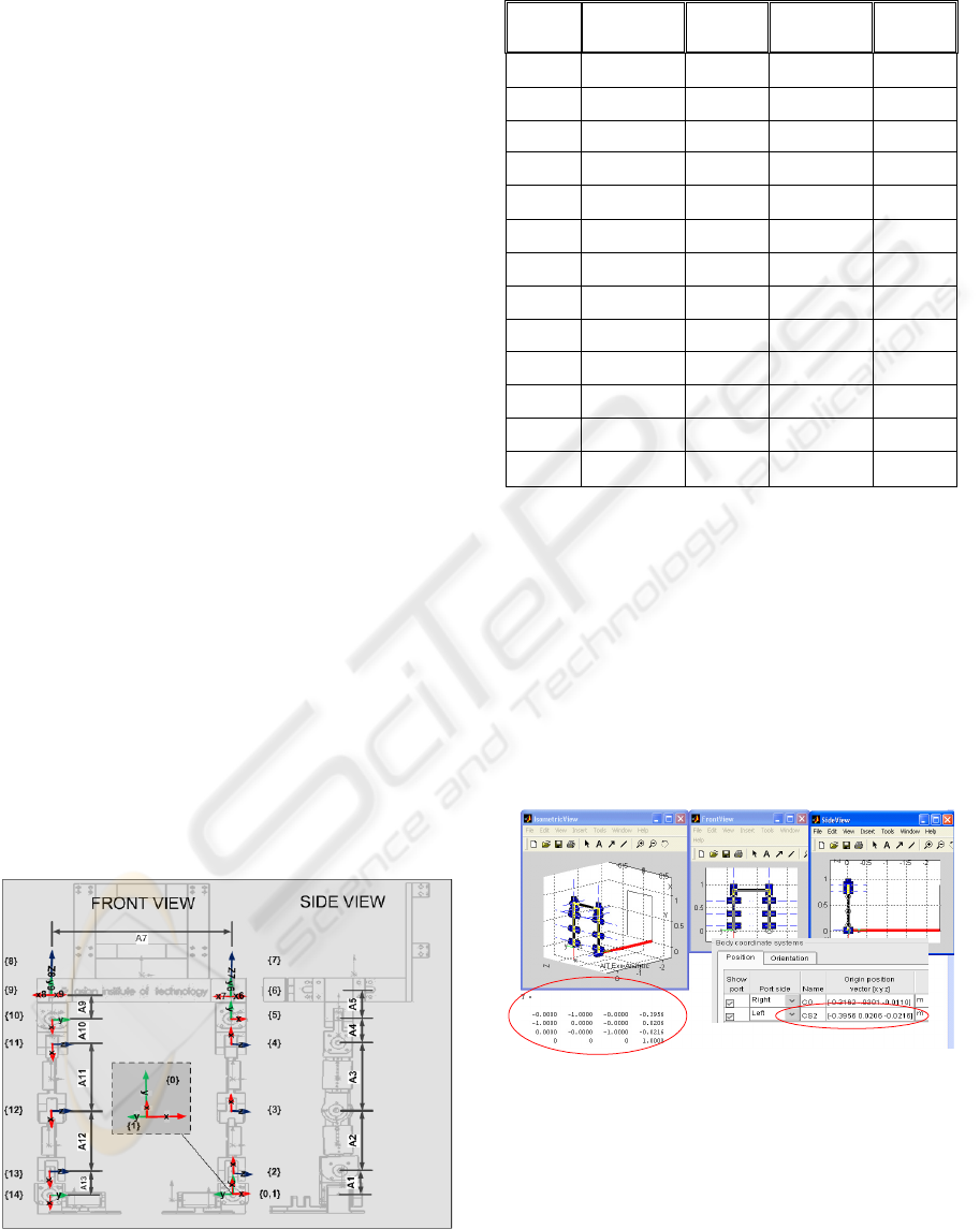
4.1 Model Verification with
Denavit-Hartenberg Matrix and
P. I. Corke’s MATLAB Robotics
Toolbox
To verify the correctness of the simulation
modelling, the authors use the DH matrix in
describing the 12-DOF ALEX-I assuming that the
left ankle is fixed to the ground as if the whole robot
is a 12-DOF manipulator with the right ankle being
the end-effector. Obviously, the dynamics behavior
of the robot with this assumption does not match the
real situation. However, the position and velocity
obtained from the DH and Jacobian matrix
consideration proves our simulation model to be
quite accurate in terms of kinematics characteristics.
Figure 7 and Table 3 conclude the properties of links
as defined by DH (Craig, 2005).
Figure 7: Assignment of coordinate systems in accordance
to DH.
Table 3: Links’ properties required for the calculation of
DH transformation matrixes and Jacobian matrices.
Link
α
[degree]
a
[m]
θ
[degree]
d
(m)
1 90 0.1 90 0
2 0 0.26 0 0
3 0 0.28 0 0
4 90 0.11 0 0
5 0 0.12 0 0
6 -90 0 90 0
7 0 0.594 0 0
8 -90 0 0 0
9 0 0.12 -90 0
10 -90 0.11 0 0
11 0 0.28 0 0
12 0 0.26 0 0
13 90 0.1 0 0
Applying the links’ properties in Table 3 with
the Robotics Toolbox written (Corke, 1996), we
obtain another version of stick diagram as shown in
Figure 8. The toolbox calculates transformation
matrix referred from the end-effector (right ankle) to
the world coordinate (left ankle) as similar to that of
our simulation model with accuracy of 1 millimeter
as shown in the highlighted numerical data. The left
circle highlights the transformation matrix resulted
from the Corke’s procedures whereas the right circle
is the data from our developed simulation model
.
Figure 8: Simulation result from P. I. Corke Robotics
Toolbox (Corke, 1996).
4.2 MATLAB Physical Model
The simulation modelling of the 12-DOF ALEX-I
has to be started with the transformation of CAD
data from the CAD application, SolidWorks, to the
physical model format in MATLAB’s
ICINCO 2008 - International Conference on Informatics in Control, Automation and Robotics
154
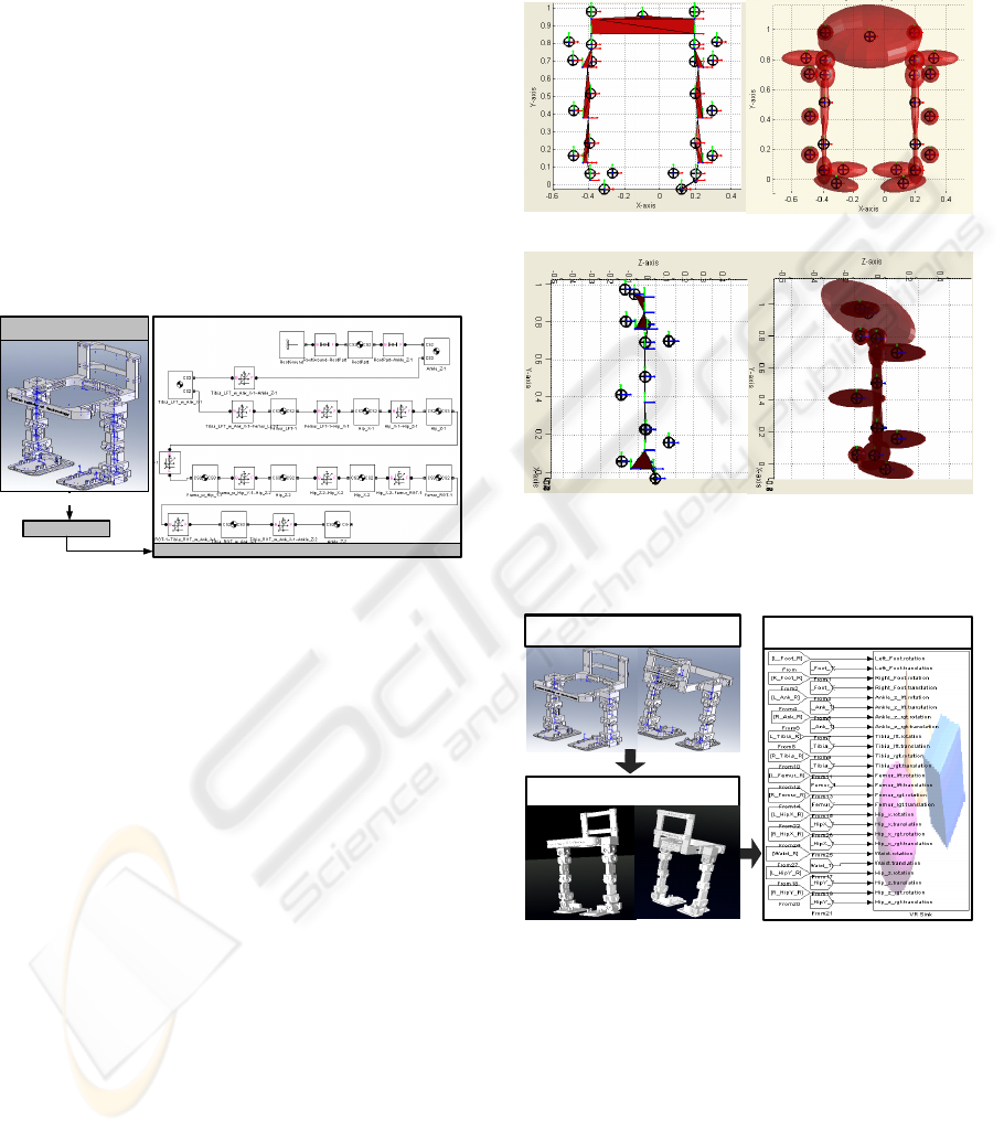
SimMechanics. The mating functions and mass
properties are automatically translated into the joints
and links with precise inertia matrices and joint
coordinate systems location as referred from the
grounded position. Figure 9 shows the flow of how
the precise simulation model can be created from
CAD assembly file format. Apparently, this
simulation model is very accurate in resembling the
real physical exoskeleton as it is created from the
exact sizes, mass and inertia properties, and joint
locations of the real fabricated links and assembled
robot. In the figure, the block diagrams with the
signs of the CGs and the signs of 5-DOF represent
the robot links and joints as defined in the mating
function respectively. Figure 10 shows the imported
frontal and lateral views of the ALEX-I model.
Filename.xml
Assembly File from
SolidWorks
MATLAB: Filename.mdl
Save as ...
Import_physmod(‘Filename.xml’)
Figure 9: Importing the physical model from SolidWorks
assembly file.
4.3 SimMechanics Virtual Sensors
Development of the simulation model on the
MATLAB environment offers great advantages
since the SimMechanics Library offers virtual
sensors that allow monitoring of kinematics and
dynamics properties of all moving bodies and joints,
including the monitoring of position, velocity,
acceleration, angular displacement, angular velocity,
angular acceleration, reaction force, and reaction
torque. More importantly, the SimMechanics also
offers virtual actuators that allow the actuation of
both the joints and the bodies by the Source toolbox
in the Simulink Library. With the virtual tools
offered by SimMechanics Library, the manipulation
of all kinematics and dynamics parameters could be
done and monitored so as to study the motion
behaviour and gait generation of the ALEX-I in
virtual environment.
Nevertheless, the numerical data observed from
the virtual sensors does not give understandable
interpretation unless applied with the graphical
visualization. The authors create the graphical
interpretation of results both in the forms of 2D
MATLAB graphics and in the 3D Virtual Reality
(VR) environment. Figure 11 shows how the motion
signals could be used as input to the 3D VR
graphics.
(a)
(b)
Figure 10: (a) Frontal and (b) Lateral views of transformed
diagram.
V-Realm Builder:
Part.VRML
SolidWorks:
Part.SLDPRT
VR Sink inputs from virtual
sensors
Figure 11: Procedures for the 3D Virtual Reality Graphical
Interpretation.
Figure 13 shows the illustrated stick diagram,
ellipsoidal mass-represented diagram, and 3D VR
animation respectively. The input signals captured
from the virtual sensors are fed to each joint for the
angular position of all joints. The signals inputted to
create the corresponding posture in Figure 13 are
shown in Table 4 and Figure 12.
θ
1-12
in the Table 4
are left ankle [z,x], left knee [x], left hip [x,z,y],
right hip [y,z,x], right knee [x], right ankle [x,z]
DESIGN AND BALANCING CONTROL OF AIT LEG EXOSKELETON-I (ALEX-I)
155
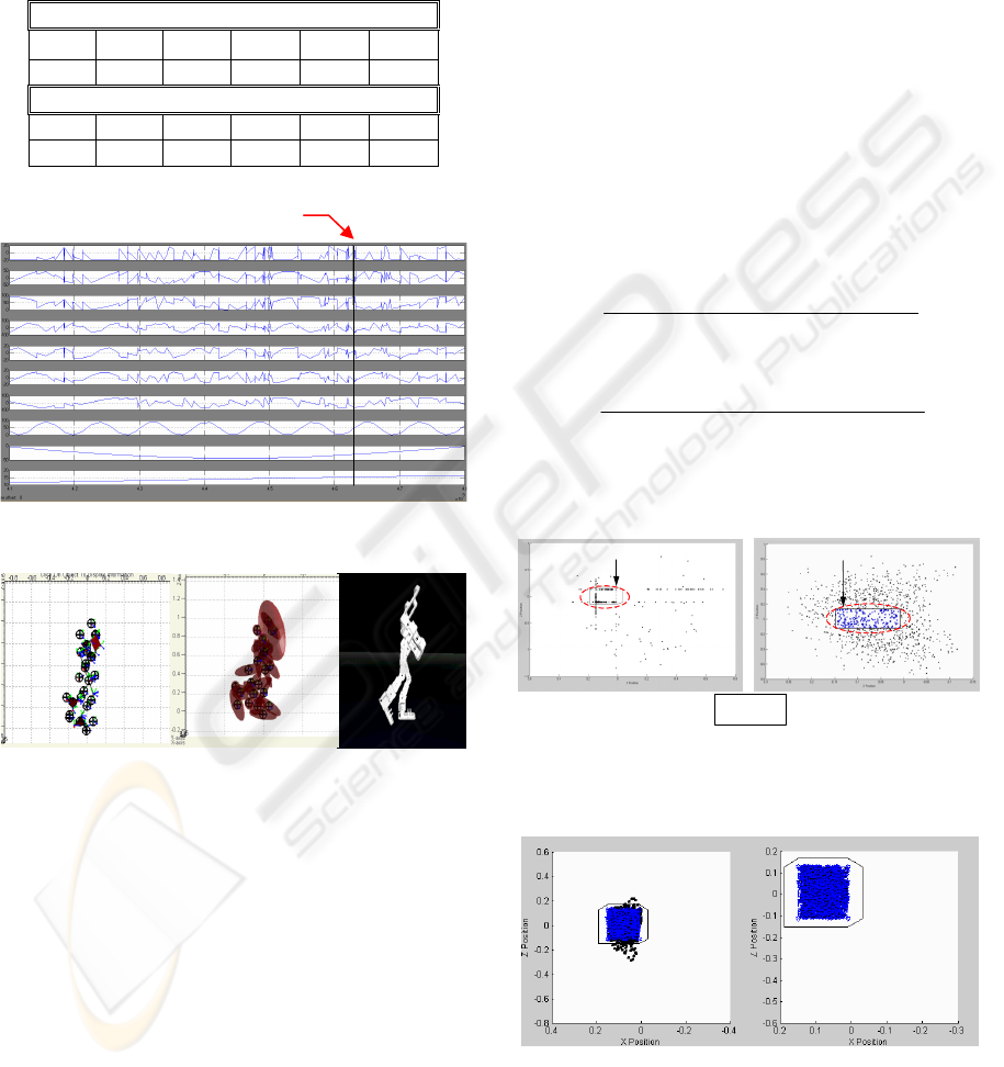
respectively. On the other hand, the input signals
observed from virtual scope in Figure 13 are listed
as the right ankle [z,x], right knee[x], right hip [x,z],
left hip [z,x], left knee [x], and left ankle [x,z] in the
order from the top to the bottom.
Table 4: 12 set-points angles.
Angles (degree)
θ
1
θ
2
θ
3
θ
4
θ
5
θ
6
0.294 36.88 58.95 -66.58 -14.98 0
Angles (degree)
θ
7
θ
8
θ
9
θ
10
θ
11
θ
12
0 -7.61 -65.15 53.73 -31.47 15.48
Figure 12: Sampled set-point signals.
(a)
(b)
(c)
Figure 13: Example of the (a) stick diagram, (b) ellipsoidal
mass-represented diagram and (c) 3D Virtual Reality
Graphical Interpretation at following set-point.
4.4 One Step Gait Motion
The generation of all geometrically feasible postures
of the exoskeleton is done using sine curves to
characterize the changes in the joint trajectories by
assuming that the left and right feet are supporting
and swinging feet respectively. The CM equations as
given in (1), (2) and (3) refer to well known zero
moment point (ZMP) equations where all
acceleration are equal to zero except g ≈ 9.81 m/s
2
.
With random sampling from all postures (6.1 x10
9
postures) while arranging them from time 0 second
to 6.1x10
9
seconds, the range of time (searching
domain) that returns stable leg-swinging postures
could be found from Figure 14 (a) between
4.18x10
9
-5.91x10
9
seconds. From the sampled
experiment, the authors could reduce size of the
searching domain from 6.1x10
9
solutions to
approximately 2x10
9
solutions. However, from the
visual interpretation in VR environment, the
postures that result from the solution numbered
4.7x10
9
to 5.91 x10
9
show the waist orientation that
would be difficult for the wearer of the exoskeleton
to move along with the exoskeleton. Therefore,
another detail simulation is performed to determine
the CM-feasible postures (joint angles) within the
searching domain 4.18 x10
9
to 4.7 x10
9
. The result is
shown in Figure 14 (b).
()
()
i i i i ix ix
iii
ZMP
i
i
my gz mzy I
z
myg
θ
+− −
=
+
∑
∑∑
∑
&&
&&
&&
&&
(1)
()
()
iiiiiziz
iii
ZMP
i
i
my gx mxy I
x
my g
θ
+− −
=
+
∑
∑∑
∑
&&
&& &&
&&
(2)
0
ZMP
y
=
(3)
ALEX-I’s Supporting Feet
* : Safe Location
. Unstable Region
(a) (b)
ALEX-I’s Supporting Feet
Figure 14: (a) Location of CM sampled over the entire
searching domain, (b) Location of CM sampled over the
reduced searching domain.
Figure 15: Filter and interpolated feasible posture CM-
save joints.
Only the postures (joints angles) that return the
balanced gait are saved into the database so that the
12 Set-Points values
ICINCO 2008 - International Conference on Informatics in Control, Automation and Robotics
156
interpolation of all feasible joints angles could be
interpolated. The filtered postures are again
interpolated to obtain very detailed joint trajectories
and filtered to get only the balanced CM joints
angles. The resulting filtered CM locations are
shown Figure 15.
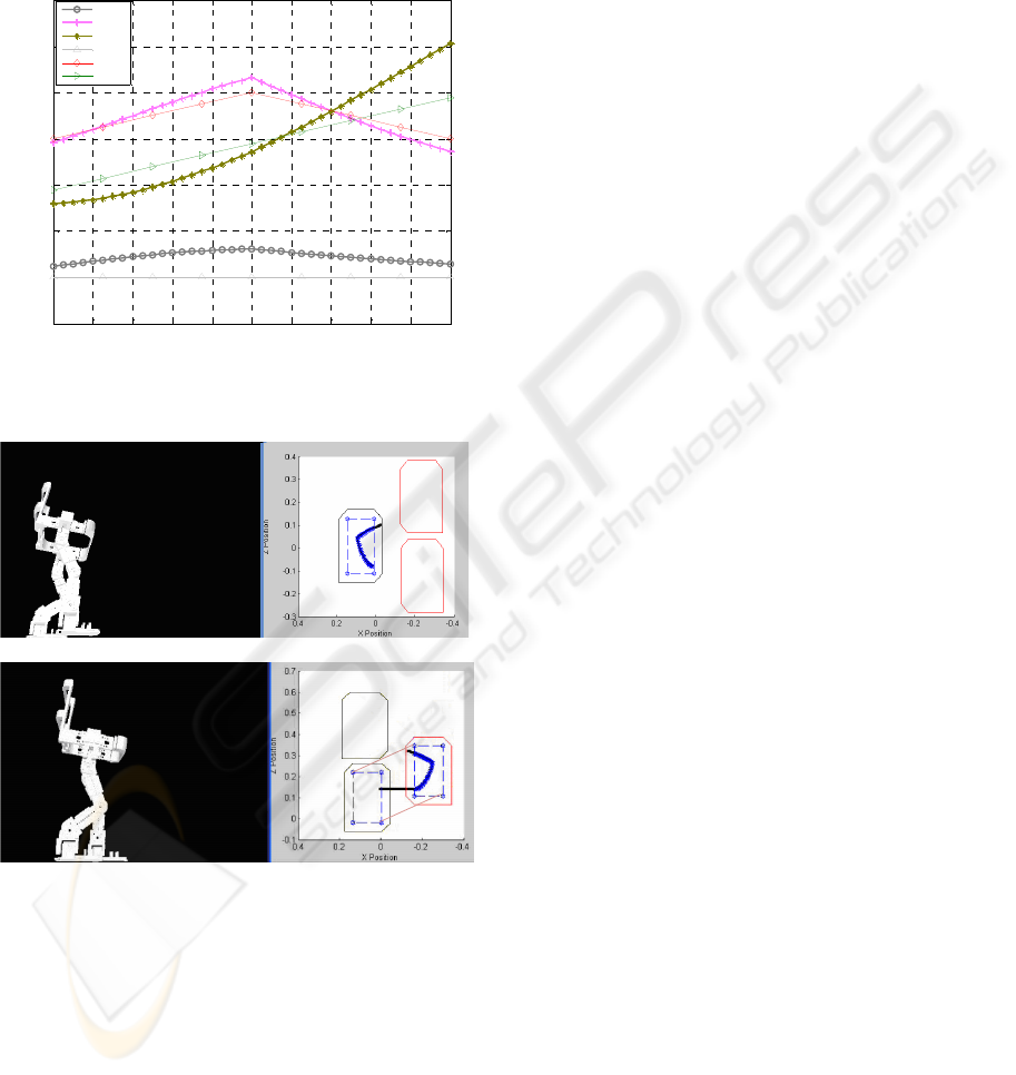
0 10 20 30 40 50 60 70 80 90 100
-0.4
-0.3
-0.2
-0.1
0
0.1
0.2
0.3
Comparison Between Real and Ideal Position of Swing Foot
Cycle (%)
Position (m)
Real X
Real Y
Real Z
Ideal X
Ideal Y
Ideal Z
Figure 16: Comparison between ideal and CM-save gait
pattern.
initial
final
(a)
initial
final
(b)
Figure 17: (a) Right-Swing step, (b) Left-Swing step.
With the feasible joint trajectories, the step
parameters, which comprise the swinging height,
step length, and step time, are obtained. After having
all joints angles in the database together with the
location of the swing foot and orientation of the
ALEX-I from the virtual sensors in the simulation
model, the one-step gait pattern is generated from
the CM-feasible joint trajectories.
In Figure 16, the ideal walking pattern and
balanced CM walking pattern are compared.
Apparently, the obtained step parameters could only
be partially achieved since the ALEX-I has to
balance itself and could not be in some particular
postures. The successful right-swing and left-swing
step are shown in the Figure 17 with the outlined
initial and final locations of the swung feet.
5 CONCLUSIONS
This paper has revealed the balancing control
analysis and design of the architecture layout of the
ALEX-I. The ALEX-I was initially controlled to
walk in open-loop manner. Position control for each
joint is operated with 32-Bits processor ARM7
controller, which senses position feedback from
1024 pulses/rev encoder. PC104 is used as a main
controller to control the entire joints controller and
to calculate all the set-points for the gait motion of
the ALEX-I. The ALEX-I simulation model has
been verified with DH matrix Robotics Toolbox and
the accurate results are observed. The model has
been further integrated to perform gait motion
analysis. The motion is captured in the form of 12
set-points observed with virtual sensors offered by
SimMechanics library. The CM-feasible balance gait
data are filtered and interpolated. One gait cycle has
been shown in the simulation and in this study. With
the obtained balanced gait motion, the data could be
set and calculated by PC104. The future works
would emphasize on the ZMP-feasible gait pattern
generation, implementation with the real wearer, and
disturbance-tolerating control system.
ACKNOWLEDGEMENTS
This research is financially supported by National
Electronics and Computer Technology Center
(NECTEC), Thailand.
REFERENCES
Aphiratsakun, N., Parnichkun, M., 2007. Preliminary
Study and Design of an Exoskeleton. Proceeding of
the CRIT 2007, Nakon Pathom, Thailand.
Chu, A., Kazerooni, H., Zoss, A., 2005. On the
Biomimetic Design of the Berkeley Lower Extremity
Exoskeleton (BLEEX). Proceeding of the 2005 IEEE
International Conference on Robotics and Automation,
Barcelona, Spain, pp. 4345-4352.
DESIGN AND BALANCING CONTROL OF AIT LEG EXOSKELETON-I (ALEX-I)
157

Corke, P. I., 1996. A Robotics Toolbox for MATLAB, IEEE
Robotics and Automation Magazine, no.1, vol.3, pp.24-
32.
Craig, J. J., 2005. Introduction to Robotics: Mechanics
and Control, Pearson Prentice Hall. 3
rd
edition.
Guizzo, E., Goldstein, H., 2005. The rise of Body Bots.
Spectrum, IEEE.
Kawamoto, Sankai, Y., 2002. Comfortable Power Assist
Control Method for Walking Aid by HAL-3.
Proceeding of the 2002 IEEE/SMC International
Conference.
Kawamoto, H., Kanbe, S., Sankai, Y., 2003. Power Assist
Method for HAL-3 Estimating Operator’s Intention
Based on Motion Information. Proceeding of the 2003
IEEE International Workshop on Robot and Human
Interactive Communication, California, USA, pp. 67-72.
Kazerooni, H., Racine, J. L., Huang, L., Steger R., 2005.
On the Control of the Berkeley Lower Extremity
Exoskeleton (BLEEX). Proceeding of the 2005 IEEE
International Conference on Robotics and Automation,
Barcelona, Spain, pp. 4353-4360.
Lee, S., Sankai, Y., 2002. Power Assist Control for Leg
with HAL-3 Based on Virtual Torque and Impedance
Adjustment. Proceedings of the 2002 IEEE/SMC
International Conference.
ICINCO 2008 - International Conference on Informatics in Control, Automation and Robotics
158
