
RFID BASED LOCATION IN CLOSED ROOMS
Implementation of a Location Algorithm using a Passive UHF-RFID System
Christoph Schönegger, Burkhard Stadlmann
University of Appled Sciences Upper Austria, Stelzhamerstr. 23, 4600 Wels, Austria
Michael E. Wernle
Meshed Systems GmbH, Alte Landstrasse 21, 85521 Ottobrunn, Germany
Keywords: Passive RFID, Location, RFID-standard-components, Positioning system, RSSI value.
Abstract: This paper presents a new concept for determining the location of an RFID-tag without any additional
hardware. For this positioning system standard RFID components with passive RFID-tags within the UHF
range are used. The measurement is based on a location algorithm which makes use of the RSSI value of the
UHF reader. The RSSI value is the return signal strength indicator and, as it is shown in the paper in hand,
this signal correlates to the distance between the RFID tag and the antenna of the reader. This positioning
system is especially useful indoors, where other positioning systems may not work. For this reason it could
prove very useful in various logistics applications. The maximum distance from antenna to the tag is
approximately between 0.5 m and 3 m. To this end a special algorithm is used to obtain stable calculation
results. A minimum of two antennas is needed to get a two-dimensional location.
1 INTRODUCTION
Identification using RFID (radio frequency
identification device) is more or less standard in
many industrial applications and in many logistics
processes. There are a variety of applications where
the combination of identification and location is very
useful.
This paper presents a solution for the location of
UHF-RFID tags within the range of a reader
antenna. For this positioning system only standard
RFID equipment is used. The concept, the
algorithm, and known limitations of the system are
presented.
2 THE BASIC IDEA
The basic concept of the positioning system is to
measure the distance between an RFID antenna and
the RFID tag using only standard RFID equipment.
The measurement of the distance is done by
interpreting the signal strength of the UHF signal.
The proposed system is especially useful for indoor
use.
2.1 Location Algorithms
There are a variety of different location methods
proposed in literature and in practical use nowadays.
Examples with RFID or WLAN can be found in
(bekkali 2007, chon 2004, ekahau 2007, geroldt
2007, ibach 2005, lionel 2004, tomberge 2004,
tsukiyama 2007). This chapter provides a
comparison between these methods. The main focus
is on determining location within buildings. This
ability could be very useful for numerous
applications in logistics.
2.1.1 Cell-of-Origin Concept
This type of positioning system makes use of an
algorithm using a mobile tag and a fixed reader.
Upon detecting a nearby reader, the tag determines
its position to be nearly equal to that of the reader.
For this the tag must be within the range of the
corresponding reader.
135
Schönegger C., Stadlmann B. and E. Wernle M. (2008).
RFID BASED LOCATION IN CLOSED ROOMS - Implementation of a Location Algorithm using a Passive UHF-RFID System.
In Proceedings of the Fifth International Conference on Informatics in Control, Automation and Robotics - ICSO, pages 135-140
DOI: 10.5220/0001484201350140
Copyright
c
SciTePress

This type of positioning system is frequently
used with RFID systems in the 125 kHz and the
13.56 MHz range. Practical applications of this type
can be found on AGV systems (autonomous guided
vehicles) or mobile robots.
A commercially available example of this type
of positioning system which uses WLAN or
Bluetooth technology is the Ekahau Positioning
Engine (ekahau 2007).
An “inverse cell-of-origin concept” is used if the
RFID reader is on the mobile unit and different tags
have a fixed position. If the reader can communicate
with a specific tag, then the position of the mobile
unit can be determined in relation to the position of
the fixed tag. An example for this concept can be
found in (tsukiyama 2007).
2.1.2 Triangulation Method
The location of a tag can be calculated by
triangulation if the distance between the tag and
several known reference stations can be determined.
The measurement of the distance can be achieved by
detecting the runtime of the radio signal or laser or
by measuring the signal strength of the radio signal.
The best known positioning system of this type
is the global positioning system (GPS). This method
also finds use in RFID systems which use active tags
and operate in the 2.45 GHz range.
2.2 RFID
An RFID system consists of two components which
communicate via radio:
a device called a “tag” or “transponder” which
is capable of storing data
a so called “reader” (providing read and write
functionality) communicates with the tags
using an appropriate antenna-system,
controller and amplifier.
Nowadays tags are very cheap as they are
produced in large numbers. Therefore they are
widely used in many goods and logistics devices.
One reader can be equipped with several
antennas. Within the range of one antenna multiple
tags can be detected and communication is organised
into a sequence of the different tags.
2.2.1 Types of RFID Systems
There are various types of RFID systems available.
Different types operate at different frequencies, have
different couplings and differ as well in the energy
supply of the transponders.
The different frequencies are
“low frequency” (119 … 148.5 kHz)
“high frequency” (13.56 MHz)
“ultra high frequency” (865 … 955 MHz)
“microwave” (2.4 … 2.5 GHz)
The different coupling technologies are inductive
coupling and modulated backscatter coupling.
Both the coupling method and the operating
frequency influence the range of operation
“close-coupling” – distance < 1 cm
“remote-coupling” – distance < 1 m
“long-range” – distance > 1 m
Tags can operate as passive tags, which get their
power from the reader via the electromagnetic field
of the antenna, or as active tags, which are powered
by a remote battery or some other power supply.
2.2.2 Applications
As mentioned above logistics applications need a
location algorithm to find a specific tag. Location,
used in combination with RFID, has the advantage
of combining identification and location using the
same hardware.
One typical example is the localisation of parcels
on a conveyor belt, persons walking through an
RFID gate carrying a transponder or the localisation
of a palette carried by a forklift. All these
applications have the need for optimised
performance, better process control and supervision.
For proper use it is important to heed the basic
limitations of this concept.
2.3 The RSSI-Value
The RSSI value (received signal strength indicator)
is a commonly used value within radio
communication systems. Modern RFID readers
within the UHF frequency range have the ability to
determine this value as a measure of the reflected
UHF signal from the tag. That is where RSSI value
gets its name “reflected signal strength indicator”.
one must consider that up to now this RSSI value
has not been standardised and is therefore
manufacturer dependent.
2.4 Used Technology
To achieve the goal of this location procedure, RFID
technology is used which has a long distance range
and is widely used in logistic systems. According to
VDI 4472 the recommended frequency for logistics
applications is 868 MHz (UHF range), which is
indeed very commonly used. UHF systems have
ICINCO 2008 - International Conference on Informatics in Control, Automation and Robotics
136
long-range readability with passive tags and the
reader normally has an output for the RSSI value.
Therefore a passive RFID system with a
frequency of 868 MHz was chosen for this particular
location system.
3 MEASURING DISTANCE
USING THE RSSI VALUE
During the project a theoretical and practical
analysis was undertaken to determine if the RSSI
value is a well-working solution for measuring
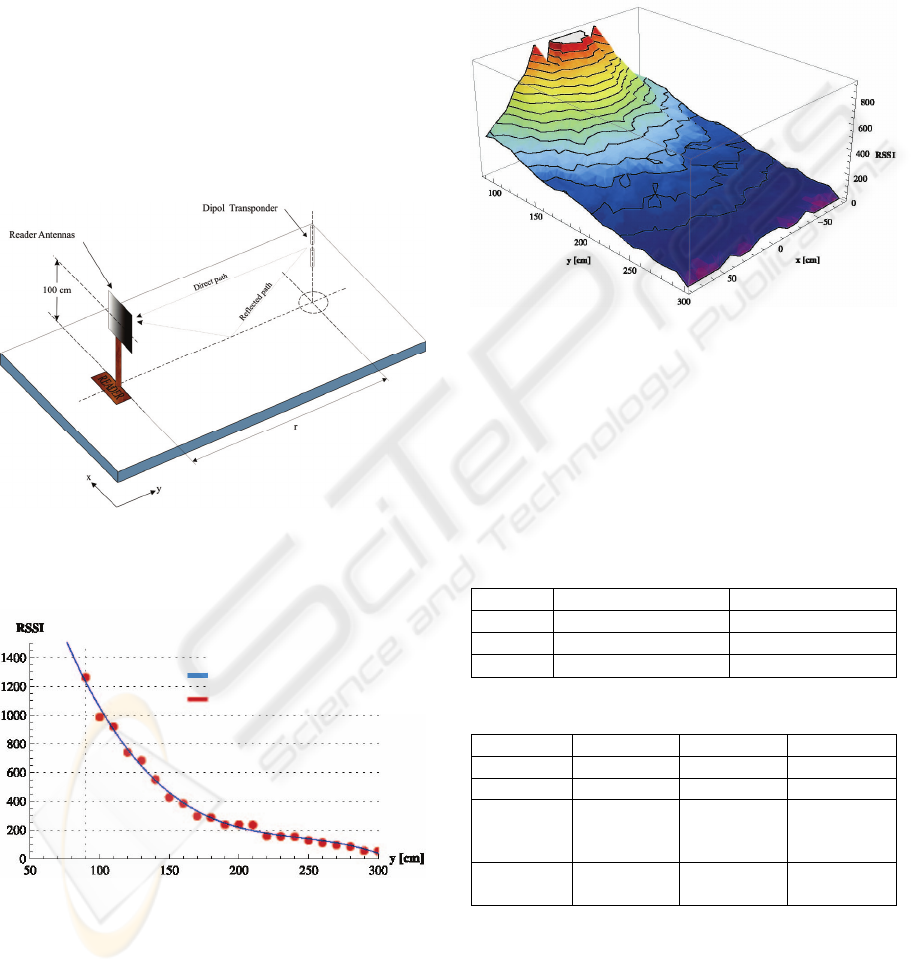
distance. Figure 1 shows the schematic design of the
lab equipment for the practical investigations.
Figure 1: Schematic view of the lab equipment used for
distance measuring.
Figure 2: Measured RSSI-values varying only the y-
coordinate of the tag-position.
For the practical measurements three different
antennas and two different kinds of tags were used.
Figure 2 and Figure 3 depict the mean value of the
RSSI value of a 10dBi antenna. Figure 2 shows the
variation of one coordinate and figure 3 the variation
of two coordinates which leads to a three-
dimensional radio-map. Each measured value is a
mean value of 1000 datasets.
If the distance between the antenna of the reader
and the tag is too low, the RSSI value may not be
obtained due to saturation, which causes a heavy
non-linear behaviour.
Figure 3: Three-dimensional radio map of the RSSI
values, varying the x and the y coordinates of the tag
position.
Three different types of antennas and two
different types of tags were investigated (see Table 1
for the tags and Table 2 for the antennas of the
reader). All antennas used have a circular right
polarisation.
Table 1: Comparison of different types of tags.
Philips TI
Chip Philips U-Code HSL RI-UHF-00C02-04
Protocol ISO 18000-6B EPCUHF Gen 2
Antenna
Dipole
λ
/2
“dog bone”
Table 2: Comparison of different antennas of the reader.
GP-ANTU RH-ANTU RH-ANTU
VSWR < 1.3 : 1 < 1.5 : 1 < 1.5 : 1
Gain [dBi] 6 > 8.5 > 10
3 dB
beamwidth
horizontal
70° 63° 55°
Max. input
power [W]
10 6 6
Due to the characteristics of the antenna on the
tag, the best result was achieved using the
combination of a
λ/2-Dipole tag and the 10dBi antenna
on the reader side.
Furthermore the influences of temperature were
also investigated. This influence must be
polynomial function 3
rd
degree
measured RSSI values
RFID BASED LOCATION IN CLOSED ROOMS - Implementation of a Location Algorithm using a Passive UHF-RFID
System
137
compensated by adequate correction algorithms
according to the measured temperature.
Additional influences are electromagnetic
disturbances caused by fluorescent lamps and, of
course, atmospheric humidity. As this system is
proposed for indoor use humidity will not influence
the system dramatically.
4 CALCULATION OF POSITION
In chapter 3 the strong correlation between the RSSI
value and the distance between antenna and tag has
been presented. To obtain the location of the tag, the
results of more than one antenna have to be
combined. During experiments in the project a two-
dimensional location was tested. To determine this
location at least two antennas are necessary which
have contact to the same tag simultaneously.
Knowing the RSSI value, it is possible to calculate a
set of positions relative to the antenna where the tag
might be based on the radio map.
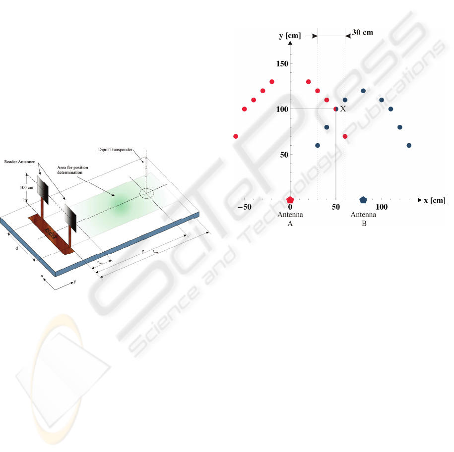
Figure 4: Schematic view of the enhanced lab equipment
for location using two antennas.
Three different calculation algorithms have been
investigated:
Numeric iteration with finite differences
Geometric intersection of polynomial
approximations
Weighted position determination
4.1 Numeric Iteration
This situation, where two antennas which
communicate with the same tag is depicted in Figure
5. Antenna A has an RSSI value which can be
located at the positions marked by red points (left
curve in figure 5), antenna B has an RSSI value
which can be located at the positions marked by blue
points (right curve).
A scenic analysis (see also bahl 2000) yields the
possible tag positions represented as a set of discrete
points from each antenna in accordance with the
measured RSSI value. The most probable tag
position is the minimum distance between the
possible locations of the two antennas within the
overlapping area. If there is only a non-zero
solution, the most probable position of the tag can be
calculated by calculating the mean value. The
Accuracy of this algorithm is, however, low.
Figure 5: Scenario of two antennas for the algorithm
“Numeric iteration”.
4.2 Polynomial Approximation
This algorithm is based on a polynomial
approximation of the line of constant RSSI value
using a least square algorithm. For each antenna one
polynomial exists for the measured RSSI value.
Figure 6 depicts the appropriate situation.
The position of the tag is the intersection of the
two polynomial functions. If this polynomial
function is of second order the error of the calculated
position is rather high. If the polynomial function is
of 5
th
order the error is very low but the calculation
effort is very high.
ICINCO 2008 - International Conference on Informatics in Control, Automation and Robotics
138
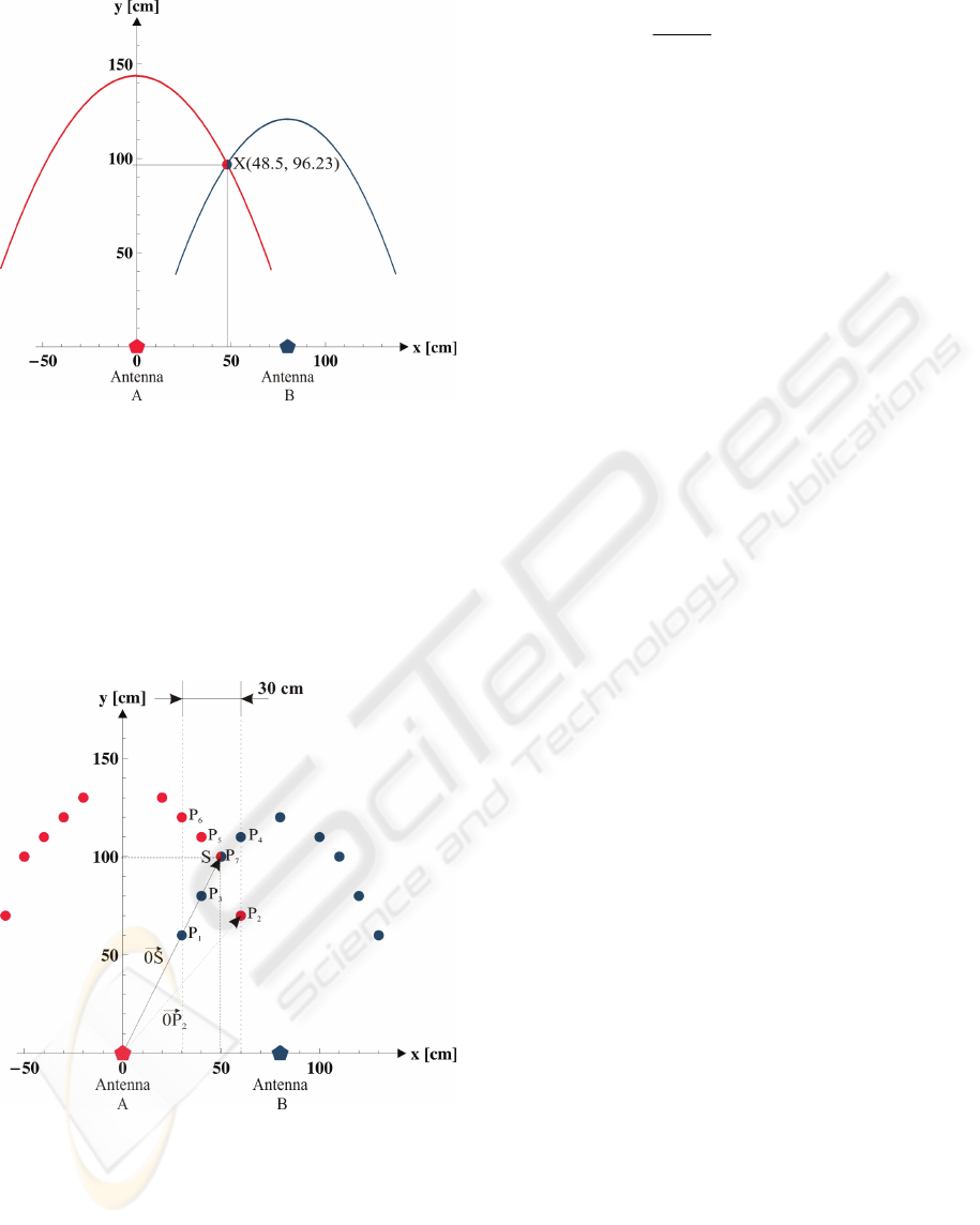
Figure 6: Scenario of two antennas for the algorithm
“polynomial approximation”.
4.3 Weighted Position Determination
Based on the same possible tag position as in chapter
4.1 the position of the tag is calculated with a
“centre of gravity calculation”. A similar algorithm
is presented in (bulusu 2000).
Figure 7: Scenario of two antennas for the algorithm
“weighted position determination”.
The position of the tag S is calculated by the
following equation:
)(
1
∑
∑
→→
⋅=
i
ii
i
i
OPm
m
OS
(1)
Hereby i are all points within the overlapping
area and m
i
are the appropriate weighting factors.
This algorithm requires fewer computing
resources and achieves a higher level of accuracy. It
combines easy computing and the possibility of
adapting the radio map, allowing for the
compensation of atmospheric humidity or other
influences.
4.4 Recommendations
Due to the previously mentioned advantages and
disadvantages the “weighted position determination”
algorithm can be considered best.
This algorithm is very stable and returns a
calculated position of the tag with respect to the
available discrete relations between RSSI value and
possible positions relative to the two antennas.
Accuracy has been checked too. In a wide part of
the space it is quite good (less than 5%) but there are
single points of rather high inaccuracy. Further
investigations have to be carried out to determine
their cause and improve this situation. Further
details can be found in (schoenegger 2007).
5 CONCLUSIONS
The paper presents the results of having investigated
an RFID based location system. Only standard RFID
equipment with passive tags operating within the
UHF range was used. Determination of location
works within a range of approximately 3 meters and
is based on the use of the reader’s RSSI value. A tag
can be located two dimensionally if it is situated
within the range of at least two readers. This
location algorithm might be used, for example, in
combination with a fork-lift, whereby the forks are
equipped with antennas. The algorithm is capable of
providing a good notion where a specific tag is
located relative to the fork.
In addition to logistics application this algorithm
may be useful for positioning of mobile robots
within production automation.
As the presented location system uses only
standard hardware and is based on a simple
calculation algorithm, it might be considered as “a
new concept”. No similar solution is known to the
authors.
RFID BASED LOCATION IN CLOSED ROOMS - Implementation of a Location Algorithm using a Passive UHF-RFID
System
139

REFERENCES
Bahl, P, Padmanabhan, V.N., 2000. RADAR: An In-
Building RF-Based User Location and Tracking
System. In Proceedings of the 19
th
International
Conference on Computer Communications
(Infocom2000), Vol. 2, pp 775-784, Tel Aviv, Israel,
March 2000.
Bekkali, A., Sanson, H., Matsumoto, M., 2007. RFID
Indoor Positioning Based on Probailistic RFID Maps
and Kalman Filtering. In 3rd IEEE International
conference on Wireless and Mobile Computing,
Networking and Communications, October 2007,
White Plains, USA, October 2007.
Bulusu, N., 2000. GPS-less low cost outdoor localization
for very small devices. In IEEE Personal
Communications Magazine, 7:28-34, October 2000.
Chon, H. D. et.al., 2004. Using RFID for Accurate
Positioning. In The 2004 International Symposium on
GNSS/GPS, Sydney, Australia, December 2004.
Ekahau, 2007. Ekahau Positioning Engine 4.0 User Guide,
http://www.ekahau.com (August 8
th
, 2007).
Finkenzeller, K., 2006. RFID-Handbuch; Grundlagen und
Anwendungen induktiver Funkanlagen, Transponder
und Kontaktloser Chipkarten, Hanser Fachbuchverlag,
4
th
edition.
Geroldt, C., Uckelmann, D., 2007. Tracking and Tracing
in Production Scenarios with Passive RFID
Transponders. In 3rd European Workshop on RFID
Systems and Technologies, Duisburg, Germany, VDE-
Verlag, June 2007.
Ibach, P., Stantchev, V., Lederer F., Weiss A., 2005.
WLAN-Based Asset Tracking for Warehouse
management. In IADIS International Conference e-
Commerce, Porto, Portugal, December 2005.
Lionel, M.Ni, Yunhao L., Yiu C.L., Abhishek P., 2004.
LANDMARC: Indoor Location Sensing Using Active
RFID. In Wireless Networks, Volume 10, Number 6,
Springer Netherlands, November 2004.
Schoenegger, C., 2007. Untersuchung der Eignung eines
passiven UHF RFID Systems für die
Positionsbestimmung in geschlossenen Räumen. In
Diploma Thesis, University of Applied Sciences Upper
Austria, School of Engineering, Wels, September
2007.
Tomberge, P., 2004. Navigation mittels RFID –
Betrachtung der Navigationsmöglichkeiten durch
RFID-Eintrittskarten bei der WM 2006. In Diploma
Thesis, University of Münster, Germany, December
2004.
Tsukiyama, T., Suzuki, A., 2007. Navigation System for
indoor Mobile Robots based on RFID Tags,
Proceedings of the 4
th
International Conference on
Informatics in Control, Automation and Robotics –
ICINCO, Angers, France, May 2007.
ICINCO 2008 - International Conference on Informatics in Control, Automation and Robotics
140
