
COMPARISON OF DIFFERENT INFORMATION FLOW
ARCHITECTURES IN AUTOMATED DATA COLLECTION
SYSTEMS
Jussi Nummela, Petri Oksa, Leena Ukkonen, Lauri Sydänheimo and Markku Kivikoski
Tampere University of Technology, Electronics Institute, Rauma Research Unit, Kalliokatu 2, 26100 Rauma, Finland
Keywords: Automated data collecting, information flow architecture, traffic load.
Abstract: Automated Data Collecting System (ADCS) is a common name for automatic systems that collect data of
any kind. These systems are becoming more and more common in several industries and play an important
part in many of today’s and future applications. Information flow architecture is an important issue, when
employing an ADCS. This paper presents different kinds of architecture models and their typical
characteristics, concentrating on traffic load issues in different parts of the system. The results presented in
this paper, give a basis for more accurate specifying and designing of the architecture model for each
automated data collecting application in question.
1 INTRODUCTION
Information flow architectures play an important
role in many present day and especially future
applications. As automatization becomes more
common in many industries, the problem of
information flow architecture must be solved. This
actually consists of several “sub-problems”: where
data is transferred, how it is transferred, where data
is stored, who can access the data, how the access is
performed, what configuration is needed and which
party performs them, how the new participant is
added etc. etc. (Jie et. al., 2006)
All the above questions must be answered to
make the system optimally suited for an intended
application. Every application has its own individual
characteristics and therefore a common answer for
the information flow architecture cannot be given.
All the options have their own pros and cons, and
these are discussed in this study. The main focus is
however in comparing throughputs and traffic loads
in different parts of the Automated Data Collecting
Systems (ADCS) and in different models.
ADCS is defined here as including all types of
automatic systems that collect any kind of data. Well
known examples can be, for example, RFID-systems,
supply chain management systems, automatic meter
reading (AMR) systems, forest fire surveillance
sensor networks or highway speed control systems.
The common factor is that systems collect data and
in some way make it available for their users.
(Bodrozic, Stipanicev, Stula, 2006; Wang et. al.,
2005)
An ADCS usually consists of data collection
units (DCU) (e.g. RFID readers or water
consumption meters), database(s), optional server(s)
and network and data links between these
components. All of the components have an effect
on the nature and behaviour of the system. Therefore,
the components must be chosen based on the needs
of the application in question. Video data stream
systems transfer large amounts of data and they
require small jitter and high throughput due to their
real time operation. AMR systems transfer small
amounts of data and also the real time demand is
very low. Supply chain management systems also
deal with small data quantities, but they might need
very short response times and delays, for example
where handling machines are exploiting the data.
EDI systems (Electronic Data Interchange) do not
usually demand real time features, but the
transferred data amount might still be high. Forest
fire surveillance sensor networks put a lot of
emphasis on energy efficiency, because of the need
for long maintenance intervals (Yu, Wang, Meng,
2005).
Depending on which application the ADCS is
designed to be used in, different attributes must be
54
Nummela J., Oksa P., Ukkonen L., Sydänheimo L. and Kivikoski M. (2008).
COMPARISON OF DIFFERENT INFORMATION FLOW ARCHITECTURES IN AUTOMATED DATA COLLECTION SYSTEMS.
In Proceedings of the Fifth International Conference on Informatics in Control, Automation and Robotics - RA, pages 54-61
DOI: 10.5220/0001484800540061
Copyright
c
SciTePress
emphasized. For AMR systems it is not
recommended or necessary to roll out a system with
effective and high-cost real time operations. In
supply chain management it can be considered
needless expense to employ a system with very high
throughput, instead of concentrating resources on
keeping delays low.
The simulations presented in this study present
the differences in traffic load in different
architectures. These results give a basis for
specifying and designing a suitable system for each
application. This paper is sectioned as follows:
chapter 2 presents three different architecture
models and their main characteristics. Chapter 3
contains the simulation descriptions and TCP theory,
and traffic load simulation results and discussion are
presented in chapter 4. Finally, chapter 5 concludes
the study and also takes a look at future work.
2 ARCHITECTURE MODELS
The simulations were done with three different types
of architecture model. These were centralized, semi-
distributed and distributed architectures. The
differences between these architectures are:
• The placement and number of data
storage(s) e.g. database(s)
• One-way or two-way traffic
• Reaching the database directly or through a
dedicated server
All links in the simulation models are marked as
A, B, C or D, depending on their characteristics. A,
B and C links have 100 Mbps capacity whereas D
has 10 Mbps. The delay for every link is 1 µs and
BER is 0 %. The same delay and BER are also used
for every node in the network as is the buffer size of
50 packets.
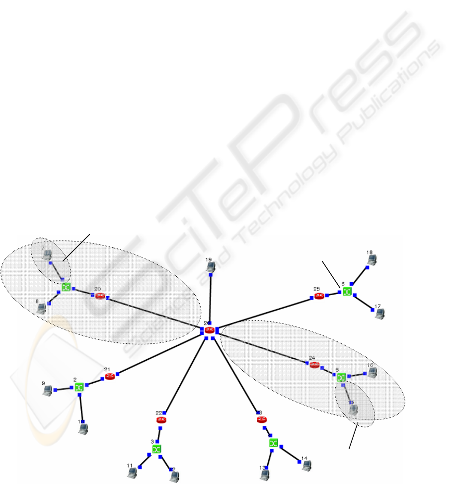
2.1 Centralized Architecture Model
The centralized architecture model consists of one
server, 12 data collection units (DCUs), 6 switches
and 7 routers (GWs) as seen in figure 2.1.
In this simplified model of centralized
architecture, all data is stored in the one dedicated
server and all users can access the data through that
server. This means that the information flow is
considered as uni-directional. The links themselves
are however bi-directional, as TCP/IP-connections
always are, because of the protocol requirements,
acknowledge-packets etc.
Figure 2.1: Centralized architecture model. Data is stored in the server.
A
SERVER
GW
DCU = Data
Collecting
Unit
DCU
SWITCH
B
C
B B C
C C
C
BRANCH 1
BRANCH 1_1
D
B
D
D
D
D D D D
BRANCH 5
BRANCH 5_1
B
C
B
D
D
D
D
COMPARISON OF DIFFERENT INFORMATION FLOW ARCHITECTURES IN AUTOMATED DATA
COLLECTION SYSTEMS
55
In this model the DCUs send their data direct to
server. Other components like switches or GWs only
forward the data packets to the following link.
2.2 Semi-Distributed Architecture
Model
The semi-distributed architecture model consists of
the same components as the centralized model and
the used topology is also similar as presented in
figure 2.1. In this model the data is however stored
in several databases, which are located in every GW.
However users will always access the data through a
dedicated server, which requests the data in question
from each database as needed. Due to these GW-
databases, only the on-demand data is transferred
beyond its own GW, which decreases the traffic load
in the server and A/B links significantly.
In this procedure, the information flow is uni-
directional between DCUs and GWs and bi-
directional between GWs and the server due to the
queries the server uses to request data from GWs.
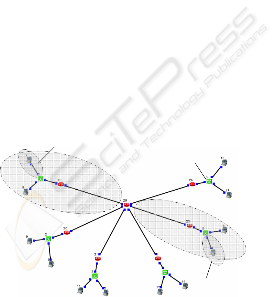
2.3 Distributed Architecture Model
Unlike the two other architecture models presented
above, the distributed architecture model does not
have a server. Other components remain the same as
in figure 2.2.
In this model users access data, or actually the
GW which hosts the database, directly from their
own branches (or subnets), not through any
dedicated server as in the previous architecture
models. The user requests the needed information
from a specific GW by sending a query packet(s).
The GW then sends the data back to the user.
3 SIMULATIONS
These simulations were performed with the NCTUns
Network simulator 3.0 by SimReal Inc, which uses a
novel kernel re-entering simulation methodology
(Wang et al 2003). The purpose of the simulations
was to find the changes in link loads between
different architectures.
3.1 Generated Traffic
The generated traffic sequence was similar in all
three architectures. The modelled time period was
40 seconds and each DCU produced data for one
continuous 10 second period. In the centralized
architecture model data was transmitted directly
from DCUs to the server, whereas in the semi-
distributed and distributed models the data was first
stored into GWs, and then requested from there by
the server or other DCU.
Figure 2.2: Distributed architecture model. Data is stored in the GWs.
GW
DCU = Data
Collecting Unit
DCU
SWITCH
B
B
C
C
B
B
B C
C C
C
BRANCH 1
BRANCH 1_1
D
B
D
D
D
D D D D
D
D
D
D
BRANCH 5
BRANCH 5_1
ICINCO 2008 - International Conference on Informatics in Control, Automation and Robotics
56
These queries lasted 1 second each, as did the
answers (e.g. data transfers) for them. Each GW
received two of these queries. This means that 10 %
of the data each DCU produced was requested by the
users and transferred from the databases.
This simulated traffic used basic TCP protocol
with 1024 B of payload and all connections used
their own individual TCP port numbers
(Transmission Control Protocol, 1981). Two major
characteristics of TCP are powerful mechanisms for
error correction and congestion avoidance, which
make it suitable for this kind of use, where data is
error critical and congestions are highly likely to
exist at some point.
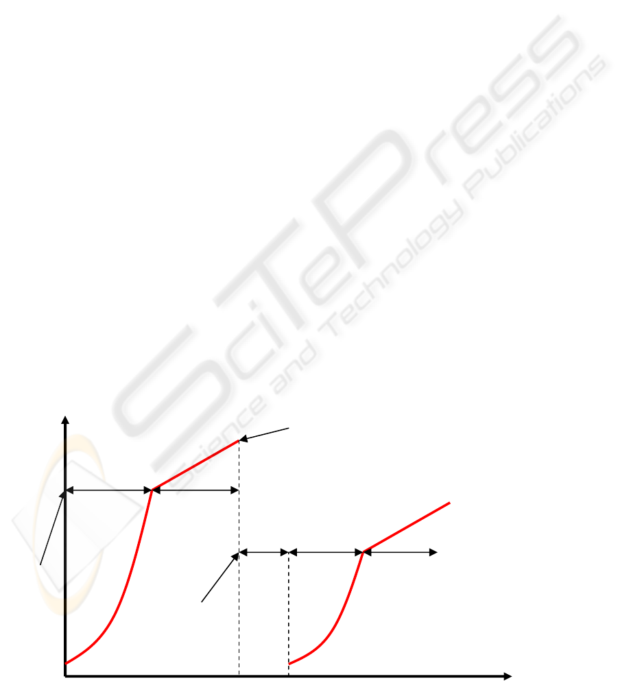
The congestion control mechanism of TCP
protocol consists of two procedures: slow start and
congestion avoidance. In slow start the extra
window for sender, the congestion window (cwnd),
will be taken into use. The congestion window
defines the number of sent segments before an
acknowledgement packet is expected to arrive. At
the beginning of transmission, the cwnd is 1. When
acknowledgement for this first sent packet arrives,
the value of cwnd is doubled. This is done after
every successful transmission. (Allman et al, 1999)
When the first error occurs, the sender switches
to the congestion avoidance procedure to reduce
growth speed and achieve network capacity less
aggressively. This switching point is called slow
start threshold, sstresh. The increase in the size of
the congestion window, and the number of sent
segments before acknowledgements, will continue.
The value is increased by one per every round trip
time. The round trip time is a calculated time for a
packet to travel from sender to receiver and the
receiver’s acknowledgement to travel back to the
original sender. The increase is now linear, whereas
in the slow start phase it was exponential. Eventually,
the packet will be lost again. Now the cwnd is reset
back to 1, and sstresh is set to the value of half the
current window size. Now the transmission
continues with the slow start procedure again, until
an error occurs, or the cwnd reaches the sstresh
value, and switches again to congestion avoidance
procedure. (Allman et al, 1999)
The transmission continues performing these
mechanisms, all the time seeking the current
maximum network capacity. It is important to
realize, that the sstresh does not always fall, it can
also rise. If the error in congestion avoidance occurs
when the window size is more than twice the sstresh,
the sstresh will increase. The following figure 3.1
presents the changes in the cwnd and sstresh during
slow start and congestion avoidance procedures.
Other TCP congestion avoidance algorithms have
also been developed, but they are not discussed here,
since the focus of this study is in architecture models,
not in protocols (Wikipedia, 2007).
TCP protocol was selected for these simulations
because it is very commonly used in several kinds of
applications and is designed to act well in difficult
circumstances. Another protocol option considered
was User Datagram Protocol (UDP), which is
“lighter” and a connectionless protocol. UDP does
not have error correction or congestion avoidance
procedures, but because of its low overhead features,
it would suit low-power consumption systems well.
However systems demanding very low power
consumption usually have their own application
specific and customized protocols, such as the Kilavi
protocol used in building automation (
Soini et. al.,
2006)
.
Figure 3.1: The use of congestion window and slow start threshold in TCP transmission (Allman et al, 1999).
Time
slow start
slow start congestion
avoidance
congestion
avoidance
ssthresh
Error occurs by congestion!
Then,
cwnd = 1
ssthresh = current window size / 2
time-
out
new
ssthresh
Congestion
window
COMPARISON OF DIFFERENT INFORMATION FLOW ARCHITECTURES IN AUTOMATED DATA
COLLECTION SYSTEMS
57
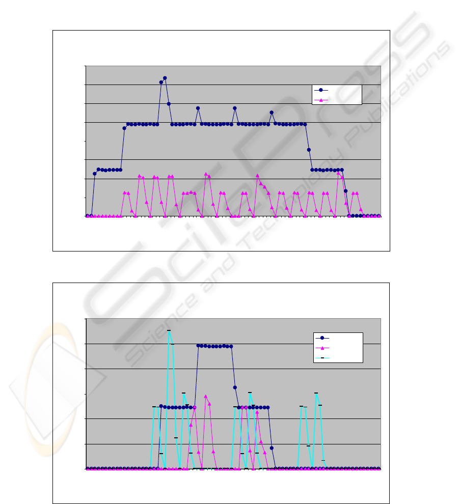
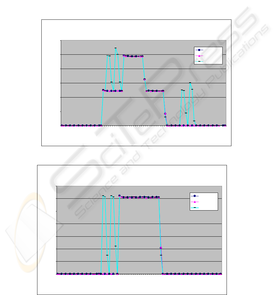
4 RESULTS AND DISCUSSION
Throughputs in A- and B-links can be seen from the
following graphs. The figure 4.1 shows server link A
traffic load in centralized and semi-distributed
architectures.
As can be seen, the throughput is substantially
lower in the semi-distributed architecture than in the
centralized model. This also leads to much lower
load on and requirements for the dedicated server.
The traffic in link B is shown in figure 4.2. The
picture presents the corresponding graphs from three
different architectures. The presented load is
measured from branch 5 (as in the graphs in figures
4.3 and 4.4).
As can now be seen, the traffic load in the
centralized model is much higher and more
continuous than in the other two models. The
distributed model has more “spikes” than the semi-
distributed, due to data queries, which come directly
from DCUs and not from the dedicated server. These
queries also produce traffic for link B.
Throughputs in Server link A
Centralized & Semi Distributed Architecture
0
1000
2000
3000
4000
5000
6000
7000
8000
0
.
5
2
.
0
3
.
5
5
.
0
6
.
5
8.0
9.5
11
.
0
12
.
5
14
.
0
15
.
5
17
.
0
1
8
.5
2
0
.0
2
1
.5
23.0
24.5
26
.
0
27
.
5
29
.
0
30
.
5
32
.
0
3
3
.5
3
5
.0
3
6
.5
38.0
39.5
Time (s)
Throughput (kB/s)
Centralized
Semi-D
Figure 4.1: Link A throughputs in centralized and semi-distributed architecture models.
Throughputs in Link B (branch 5)
in different architectures
0
500
1000
1500
2000
2500
3000
0.
5
2.
0
3.5
5.
0
6.
5
8
.0
9.
5
1
1.
0
1
2
.5
1
4.0
1
5.
5
1
7.
0
1
8.5
2
0.
0
2
1.
5
2
3.0
2
4.5
2
6.
0
2
7
.5
2
9.0
3
0.
5
3
2.
0
3
3.5
3
5.
0
3
6.
5
3
8.0
3
9.
5
Time (s)
Throughput (kB/s)
Centralized
Semi-D
Distributed
Figure 4.2: Link B throughputs in all three architecture models.
ICINCO 2008 - International Conference on Informatics in Control, Automation and Robotics
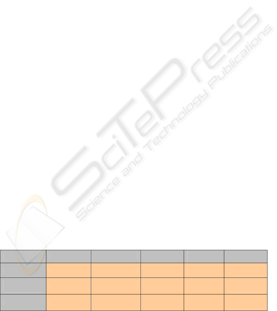
58
Examining link C it can be seen that data
collecting traffic from DCUs is similar in all
architecture models. This is presented in figure 4.3.
Graphs indicate that the only difference appears
in the distributed model, where data queries also
produce load in the link. These queries can be seen
as an extra “double spike”. In all the other situations
it does not matter which architecture model is used
when considering traffic load in link C.
These characteristics can also be seen when
examining the traffic load of link D, as can be seen
in figure 4.4.
When examining the centralized architecture
model, a few typical characteristics can be
discovered. First of all the traffic load in all links is
very high and also continuous. Huge differences
compared to the other architectures emerged in links
A and B. This leads to the conclusion that server and
link capacity must be high for centralized
architecture to work well, or alternatively, the
amount of collected data must be small. This, added
to the fact that administering this kind of one
database system is much easier and simpler than
systems with several databases due to user
Throughputs in Link C (branch 5)
in different architectures
0
500
1000
1500
2000
2500
3000
0.
5
2
.
0
3
.
5
5.0
6.
5
8
.
0
9.5
11.0
12
.
5
1
4
.0
15.5
17
.
0
18.5
20
.0
2
1
.5
23.0
24
.5
26
.
0
2
7
.5
29.0
30
.
5
3
2
.0
33
.5
3
5
.0
36.5
38
.0
3
9
.5
Time (s)
Throughput (kB/s)
Centralized
Semi-D
Distributed
Figure 4.3: Link C throughputs in all three architecture models.
Throughputs in Link D (branch 5_1)
in different architectures
0
200
400
600
800
1000
1200
1400
0.5
2.0
3.5
5.0
6.5
8.
0
9.5
11.
0
12.
5
14.
0
15.
5
17.0
18.
5
20
.
0
21.
5
23
.
0
24
.
5
26.
0
27
.
5
29.
0
30.
5
32.
0
33.
5
35.
0
36.
5
38.
0
39.
5
Time (s)
Throughput (kB/s)
Centralized
Semi-D
Distributed
Figure 4.4: Link D throughputs in all three architecture models.
COMPARISON OF DIFFERENT INFORMATION FLOW ARCHITECTURES IN AUTOMATED DATA
COLLECTION SYSTEMS
59
authentication configurations, means that centralized
architecture is suitable for ADCS if the system is
small and the amount of collected data is also
relatively small. Also adding a new DCU is quick
and easy because it only communicates with one
partner, the server.
The semi-distributed architecture model
produced significantly less traffic than the
centralized model with the systems main links A and
B. This is because only required information is
transferred beyond the databases (or gateways in this
case). A semi-distributed model is however more
complicated to administer, because of distributed
resources and databases throughout the system. On
the other hand these divided resources do reduce the
requirements placed on the equipment, which makes
the whole ADCS more reliable and cost-effective.
Adding a new DCU or configuring user
authentication rules for semi-distributed systems is
easy, because all the information is distributed
through one dedicated server, which is the only
communication partner for the databases. The semi-
distributed architecture model is therefore suitable
for automated data collecting systems, which have
rather large numbers of DCUs and architecture or
topology which might change regularly.
The distributed architecture model differs from
the other two, because it does not have a server or
server link A. The traffic load in link B is quite
similar to that of the semi-distributed model, but the
distributed model has data queries coming from
DCUs too. This slightly increases the throughput,
but still the traffic load is much lower than in the
centralized model. The distributed model is hard to
administer, because of the several databases and
communication partners all over the system. Adding
a DCU is also complicated, because it needs to
communicate and authenticate with several partners.
The distributed architecture model is most suitable
for an ADCS with a large amount of data and many
DCUs, but the architecture is likely to be fixed and
new users or DCUs are not expected to be added
frequently.
The traffic load in links C or D is very similar in
all simulated architectures. Only the distributed
model has slightly more traffic here, because data
queries come straight from DCUs. Still, the
difference is marginal, when most of the traffic load
is generated from collected data which is similar in
all models.
The security aspects constitute an entity which,
despite being essential for each application, is not
discussed extensively in this paper. The main
security issues for information flow architectures are
user authentication and data encryption, which differ
more or less for each model. The common factor is
that they usually increase system complexity and
also traffic load in each model. The need and level
of encryption is strongly dependent on the nature of
application in use. User authentication, on the other
hand, is substantially different for each architecture
models, due to different numbers of communication
partners, as mentioned earlier. These aspects
however require more specific investigation to
accurately determine requirements and possibilities
for different user authentication methods.
(Sikkilä et.
al., 2006; Perrig et. al., 2002)
The main characteristics of all three studied
models are summarized in the following table 4.1.
5 CONCLUSIONS AND FUTURE
WORK
This paper presented three different information
flow architecture models for automated data
collecting systems, and the main characteristics of
each of them. Comparisons of the traffic loads in
each part of the systems were also presented, and
suitable models for different application types were
recommended. These presented results can be used
as a basis for designing and specifying an
application-specific automated data collecting
system.
Table 4.1: The main characteristics of different information flow architecture models for ADCS.
Model Traffic load Maintenance Modifiability
Number of
DCUs
Example
applications
Centralized
High Very easy Very good Small
Video
surveillance
Semi-
Distributed
Low Easy Good Large
Water meter
reading
Distributed
Low Hard Bad Very large
Supply chain
management
ICINCO 2008 - International Conference on Informatics in Control, Automation and Robotics
60

As mentioned earlier, every application has its
own characteristics and requirements for ADCS.
Therefore more application specific studies must be
made with each area of intended use in mind. In
supply chain management the supply chain must be
accurately studied, because even supply chains for
different products may have very different needs. In
AMR systems the metering environment and needs
must be strictly surveyed to achieve an optimal
outcome. Therefore this study will be continued with
a more accurate definition of the supply chain in the
paper reel industry and implementation of an RFID-
based ADCS in the paper industry environment.
Also the security issues such as user authentication
methods will be studied more deeply to determine
the procedure options and requirements for adding
new parts and partners to ADCS.
REFERENCES
Allman, M., et. al. (1999). IETF Standards Track, RFC
2581, “TCP Congestion Control”.
<http://www.ietf.org/rfc/rfc2581.txt>. The Internet
Engineering Task Force. Accessed 7 Aug. 2007.
Bodrozic, L., Stipanicev, D., Stula, M. (2006). “Agent
based data collecting in forest fire monitoring system”.
International Conference on Software in
Telecommunications and Computer Networks, 2006.
SoftCOM 2006. Sept. 29 – Oct. 1 2006. IEEE.
Page(s): 326 – 330.
Jie, W., Hung, T., Turner, S. J., Cai, W. (2006).
“Architecture Model for Information Service in Large
Scale Grid Environments”. Proceedings of the Sixth
IEEE International Symposium, on Cluster Computing
and the Grid 2006. CCGRID ’06. Volume 1, 16-19
May 2006, IEEE. Pages: 107-114.
Perrig, A., Szewczyk, R., Wen, V., Culler, D., Tygar, J.D.
(2002). “SPINS: Security Protocols for Sensor
Networks”. Wireless Networks Journal, Volume 8,
Issue 5 (Sept. 2002). Pages: 521-534. Springer
Netherlands.
Sikkilä, H., Soini, M., Oksa, P., Sydänheimo, L.,
Kivikoski, M. (2006). ”KILAVI Wireless
Communication Protocol for the Building
Environment – Security Issues”. IEEE Tenth
International Symposium on Consumer Electronics,
2006. ISCE ’06. IEEE.
Soini, M., Sikkilä, H., Oksa, P., Sydänheimo, L.,
Kivikoski, M. (2006). ”KILAVI Wireless
Communication Protocol for the Building
Environment – Networking Issues”. IEEE Tenth
International Symposium on Consumer Electronics,
2006. ISCE ’06. IEEE.
Transmission Control Protocol (1981). IETF Standards
Track, RFC 793. “Transmission Control Protocol”.
<http://tools.ietf.org/rfc/rfc793.txt>. The Internet
Engineering Task Force, September 1981. Accessed
20 Aug. 2007.
Wang, K., Su, R., Li, Z., Cai, Z., Zhou, L. (2005). “Study
of Secure Complicated Information System
Architecture Model”. Proceedings of the First IEEE
International Conference on Semantics, Knowledge
and Grid, 2005. SKG’05. IEEE, Nov 2005. Page(s):
101-101.
Wang, S. Y., Chou, C. L., Huang, C. H., Hwang, C. C.,
Yang, Z. M., Chiou, C. C., Lin, C. C. (2003). “The
Design and Implementation of the NCTUns 1.0
Network Simulator”. Computer Networks, Vol. 42,
Issue 2, June 2003, Page(s): 175-197
Wikipedia, The Free Encyclopedia (Updated 24.7.2007).
“TCP Congestion Avoidance Algorithm”. [Online],
Available:
http://en.wikipedia.org/wiki/TCP_congestion_avoidan
ce_algorithm. Accessed 13 Aug. 2007.
Yu, L., Wang, N., Meng, X. (2005). “Real-time Forest
Fire Detection with Wireless Sensor Networks”.
Proceedings on IEEE International Conference on
Wireless Communication, Networking and Mobile
Computing, 2005. IEEE, Volume 2, 23-26 Sept. 2005
Page(s): 1214 – 1217.
COMPARISON OF DIFFERENT INFORMATION FLOW ARCHITECTURES IN AUTOMATED DATA
COLLECTION SYSTEMS
61
