PHASE
LOCKED LOOPS DESIGN AND ANALYSIS
Nikolay V. Kuznetsov, Gennady A. Leonov and Svetlana S. Seledzhi
Saint-Petersburg State University, Universitetski pr. 28, Saint-Petersburg, 198504, Russia
Keywords:
Mathematical model, stability, Phase-locked loops, Costas loop.
Abstract:
New methods, for the design of different block diagrams of PLL, using the asymphtotic analysis of high-
frequency periodic oscillations, are suggested. The PLL description on three levels is made: 1) on the level of
electronic realizations; 2) on the level of phase and frequency relations between inputs and outputs in block
diagrams; 3) on the level of differential and integro-differential equations. On the base of such description, the
block diagram of floating PLL for the elimination of clock skew and that of frequency synthesizer is proposed.
The rigorous mathematical formulation of the Costas loop for the clock oscillators are first obtained. The
theorem on a PLL global stability is proved.
1 INTRODUCTION
The phase-locked loops are widespread in a mod-
ern radio electronics and circuit technology (Viterbi,
1966; Gardner, 1966; Lindsey, 1972; Lindsey and
Chie, 1981; Leonov, Reitmann and Smirnova, 1992;
Leonov, Ponomarenko and Smirnova, 1996; Leonov
and Smirnova, 2000; Kroupa, 2003; Best, 2003,
Razavi, 2003; Egan, 2000; Abramovitch, 2002). In
this paper the technique of PLL description on three
levels is suggested:
1) on the level of electronic realizations,
2) on the level of phase and frequency relations
between inputs and outputs in block-diagrams,
3) on the level of differential and integro-
differential equations.
The second level, involving the asymptotical anal-
ysis of high-frequency oscillations, is necessary for
the well-formed derivation of equations and for the
passage on the third level of description. For example,
the main for the PLL theory notion of phase detector
is formed exactly on the second level of consideration.
In this case the characteristic of phase detector de-
pends on the class of considered oscillations. While
in the classical PLL it is used the oscillation multi-
pliers, for harmonic oscillations, the characteristic of
phase detector is also harmonic, for the impulse os-
cillations (for the same electronic realization of feed-
back loop) it is a continuous piecewise-linear periodic
function.
In the present work the development of the above-
mentioned technique for PLL is pursued. Here for
the standard electronic realizations, the characteristics
of phase detectors are computed and the differential
equations, describing the PLL operation, are derived.
Here together with usual PLL the Costas loop is
also considered. The essential conclusion is that the
Costas loop with impulse oscillators tunes to a half
frequency of master oscillator.
2 BLOCK DIAGRAM AND
MATHEMATICAL MODEL OF
PLL
Consider a PLL on the first level (Fig.1)
Figure
1: Electronic circuit of PLL.
Here OSC
master
is a master oscillator, OSC
slave
is a
slave oscillator, which generates high-frequency ”al-
most harmonic oscillations”
f
j
(t) = A
j
sin(ω
j
(t)t + ψ
j
). (1)
Block × is a multiplier of oscilations of f
1
(t) and
f
2
(t). At its output the signal f
1
(t) f
2
(t) arises. The
relations between the input ξ(t) and the output σ(t) of
114
Kuznetsov N., Leonov G. and Seledzhi S. (2008).
PHASE LOCKED LOOPS DESIGN AND ANALYSIS.
In Proceedings of the Fifth International Conference on Informatics in Control, Automation and Robotics - SPSMC, pages 114-118
DOI: 10.5220/0001485401140118
Copyright
c
SciTePress
linear filter have the form
σ(t) = α
0
(t) +
t
Z
0
γ(t − τ)ξ(τ)dτ.
Here γ(t) is an impulse transient function of filter,
α
0
(t) is an exponentially damped function, depend-
ing on the initial date of filter at the moment t = 0.
Now we reformulate the high-frequency property
of oscillations f
j
(t) to obtain the following condition.
Consider the great fixed time interval [0,T ], which
can be partitioned into small intervals of the form
[τ,τ + δ], (τ ∈ [0, T ]), where the following relations
|γ(t) − γ(τ)| ≤ Cδ, |ω
j
(t) − ω
j
(τ| ≤ Cδ,
∀t ∈ [τ,τ + δ], ∀τ ∈ [0,T ],
(2)
|ω
1
(τ) − ω
2
(τ)| ≤ C
1
, ∀ τ ∈ [0, T ], (3)
ω
j
(t) ≥ R, ∀t ∈ [0,T ] (4)
are satisfied. Here we assume that the quantity δ is
sufficiently small with respect to the fixed numbers
T,C,C
1
, the number R is sufficiently great with re-
spect to the number δ.
The latter means that on the small intervals [τ,τ +
δ] the functions γ(t) and ω
j
(t) are ”almost constants”
and the functions f
j
(t) rapidly oscillate as harmonic
functions. It is clear that such conditions occur for
high-frequency oscillations.
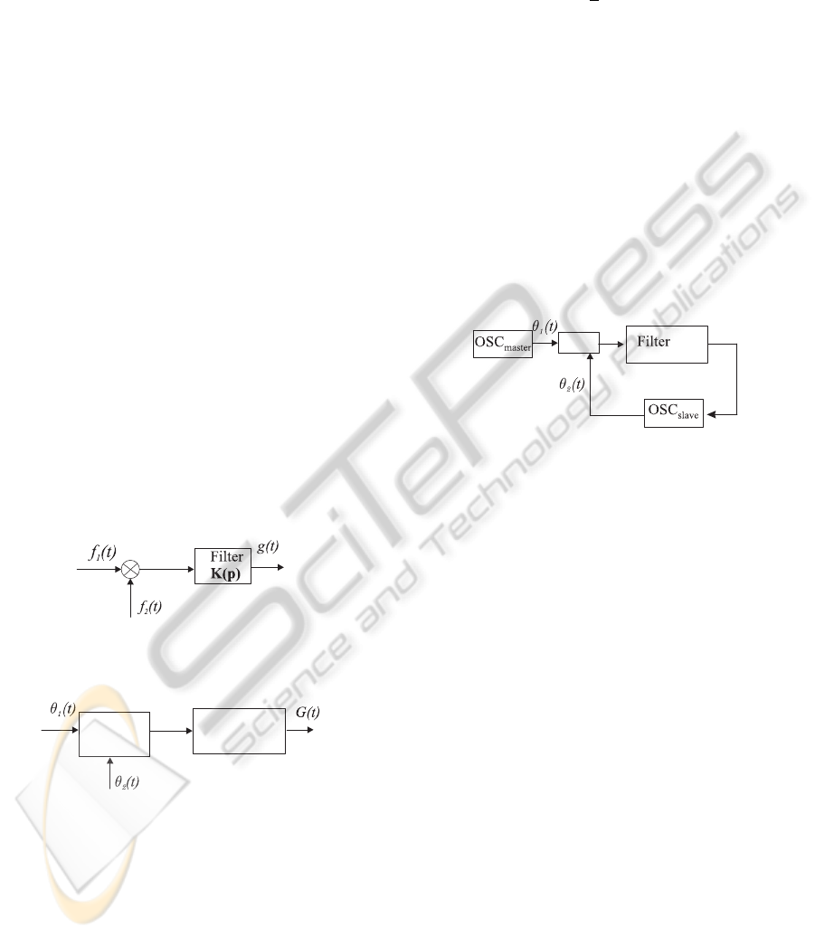
Consider two block diagram described in Fig. 2
and 3.
Figure 2: Multiplier and filter with transfer function K(p).
Filter
K(p)
PD
Figure 3: Phase detector and filter.
Here θ
j
(t) = ω
j
(t)t + Ψ
j
are phases of the oscil-
lations f
j
(t), PD is a nonlinear block with the charac-
teristic ϕ(θ), being called a phase detector (discrimi-
nator). The phases θ
j
(t) enter the inputs of PD block
and the output is the function ϕ(θ
1
(t) − θ
2
(t)).
The signals f
1
(t) f
2
(t) and ϕ(θ
1
(t) − θ
2
(t)) enter
the same filters with the same impulse transient func-
tion γ(t). The filter outputs are the functions g(t) and
G(t) respectively.
A classical PLL synthesis is based on the follow-
ing result
Theorem 1. If conditions (2)–(4) are satisfied and
ϕ(θ) =
1
2
A
1
A
2
cosθ,
then for the same initial data of filter the following
relation
|G(t) − g(t)| ≤ C
2
δ, ∀t ∈ [0,T ].
is valid. Here C
2
is a certain number not depending
on δ.
Thus, the outputs of two block-diagrams in Fig. 2
and Fig. 3: g(t) and G(t), differ little from each other
and we can pass (from a standpoint of the asymptotic
with respect to δ) to the following description level,
namely to the level of phase relations 2).
In this case a block diagram in Fig. 1 passes to the
following block diagram (Fig. 4)
PD
Figure 4: Block diagram of PLL on the level of phase rela-
tions.
Consider now the high-frequency oscillators, con-
nected by a diagram in Fig. 1. Here
f
j
(t) = A
j
sign sin(ω
j
(t)t + ψ
j
). (5)
We assume, as before, that conditions (2)–(4) are sat-
isfied.
Consider a 2π-periodic function ϕ(θ) of the form
ϕ(θ) =
½
A
1
A
2
(1 + 2θ/π) for θ ∈ [−π, 0],
A
1
A
2
(1 − 2θ/π) for θ ∈ [0, π].
(6)
and block-diagrams in Fig. 2 and 3.
Theorem 2. If conditions (2)–(4) are satisfied and
the characteristic of phase detector ϕ(θ) has the form
(6), then for the same initial data of filter the following
relation holds
|G(t) − g(t)| ≤ C
3
δ, ∀t ∈ [0,T ].
Here C
3
is a certain number not depending on δ.
Theorem 2 is a base for the synthesis of PLL with
impulse oscillators. It permits us for the impulse
clock oscillators to consider two block-diagrams in
parallel: on the level of electronic realization (Fig. 1)
and on the level of phase relations (Fig. 4), where the
common principles of the phase synchronization the-
ory can be applied. Thus, we can construct the theory
PHASE LOCKED LOOPS DESIGN AND ANALYSIS
115
of phase synchronization for the distributed system of
clocks in multiprocessor cluster.
Let us make a remark necessary to derive the dif-
ferential equations of PLL.
Consider a quantity
˙
θ
j
(t) = ω
j
(t) +
˙
ω
j
(t)t.
For the well-synthesized PLL, namely possessing
the property of global stability, we have an exponen-
tial damping of the quantity
˙
ω
j
(t):
|
˙
ω
j
(t)| ≤ Ce
−αt
.
Here C and α are certain positive numbers not de-
pending on t. Therefore the quantity
˙
ω
j
(t)t is, as a
rule, sufficiently small with respect to the number R
(see condition (2)– (4)).
From the above we can conclude that the follow-
ing approximate relation
˙
θ
j
(t) = ω
j
(t) (7)
is valid. When derived the differential equations of
this PLL, we make use of a block diagram in Fig. 4
and relation (7),which is assumed to be valid precisely
.
Note that, by assumption, the control low of tun-
able oscillators is linear:
ω
2
(t) = ω
2
(0) + LG(t). (8)
Here ω
2
(0) is the initial frequency of tunable os-
cillator, L is a certain number, G(t) is a control signal,
which is a filter output (Fig. 4).
Thus, the equation of PLL is as follows
˙
θ
2
(t) = ω
2
(0)+L(α
0
(t)+
t
Z
0
γ(t −τ). ϕ(θ
1
(τ)−θ
2
(τ))dτ).
Assuming that the master oscillator such that ω
1
(t) ≡
ω
1
(0), we obtain the following relations for PLL
(θ
1
(t) − θ
2
(t))
•
+ L(α
0
(t) +
t
Z
0
γ(t − τ).
ϕ(θ
1
(τ) − θ
2
(τ))dτ) = ω
1
(0) − ω
2
(0).
(9)
This is an equation of PLL.
Applying the similar approach, we can conclude
that in PLL the filters with transfer functions of more
general form can be used:
K(p) = a +W (p),
where a is a certain number, W (p) is a proper frac-
tional rational function. In this case in place of equa-
tion (9) we have
(θ
1
(t) − θ
2
(t))
•
+ L(a(ϕ(θ
1
(t) − θ
2
(t))+
+ α
0
(t) +
t
Z
0
γ(t − τ)ϕ(θ
1
(τ) − θ
2
(τ))dτ) =
= ω
1
(0) − ω
2
(0).
(10)
In the case when the transfer function of the filter
a+W (p) is non degenerate, i.e. its numerator and de-
nominator do not have common roots, equation (10)
is equivalent to the following system of differential
equations
˙z = Az + bψ(σ)
˙
σ = c
∗
z + ρψ(σ).
(11)
Here A is a constant n ×n-matrix, b and c are constant
n × n-vectors, ρ is a number, ψ(σ) is a 2π-periodic
function, satisfying the relations ρ = −aL
W (p) = L
−1
c
∗
(A − pI)
−1
b,
ψ(σ) = ϕ(σ) −
ω
1
(0) − ω
2
(0)
L(a +W (0))
.
Note that in (11) σ = θ
1
− θ
2
.
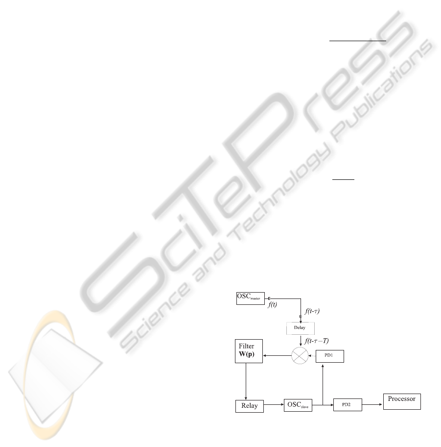
Using Theorem 2, we can make the design of a
block diagram of floating PLL, which plays a role of
the function of frequency synthesizer and the function
of correction of the clock-skew (see parameter τ in
Fig. 5).
Such a block diagram is shown in Fig. 5.
Here OSC
master
is a master oscillator, Delay is
a time-delay element, Filter is a filter with transfer
function
W (p) =
β
p + α
,
OSC
slave
is a slave oscillator, PD1 and PD2 are pro-
grammable dividers of frequencies, Processor is a
processor.
The Relay element plays a role of floating correct-
ing block. The introduction of it allow us to null a
residual clock skew, which arises for the nonzero ini-
tial difference of frequencies of master and slave os-
cillators.
Figure 5: Block diagram of PLL.
Note, the electronic realization of clock and delay
can be found in (Ugrumov, 2000; Razavi, 2003) and
that of multipliers, filters, and relays in (Aleksenko,
2004; Razavi, 2003). The description of dividers of
frequency can be found in (Solonina et al., 2000).
ICINCO 2008 - International Conference on Informatics in Control, Automation and Robotics
116
Assume, as usual, that the frequency of master os-
cillator is constant, namely ω
1
(t) ≡ ω
1
= const. The
parameter of delay line T is chosen in such a way that
ω
1
(T + τ) = 2πk + 3π/2. Here k is a certain natural
number, ω
1
τ is a clock skew.
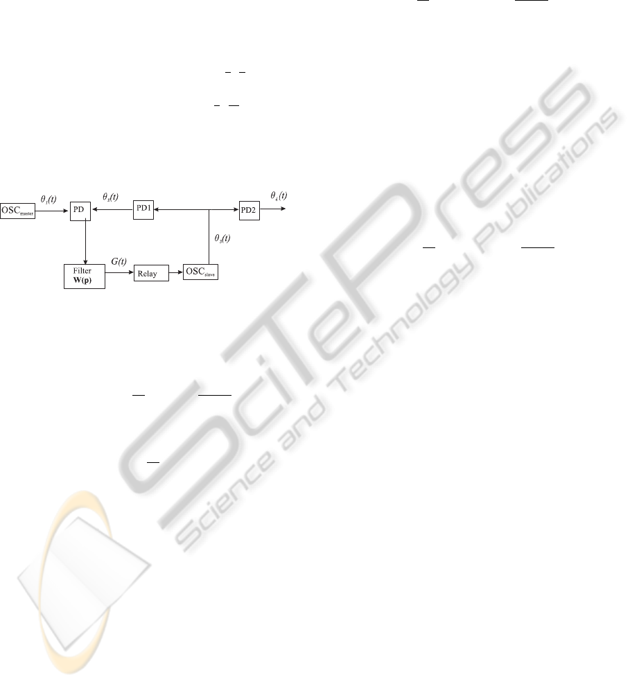
By Theorem 2 and the choice of T the block dia-
gram, shown in Fig. 6, can be changed by the close
block diagram, shown in Fig. 6.
Here 2π is a periodic characteristic of phase de-
tector. It has the form
ϕ(θ) =
2A
1
A
2
θ/π forθ ∈ [−
π
2
,
π
2
]
2A
1
A
2
(1 − θ/π) forθ ∈ [
π
2
,
3π
2
],
(12)
θ
2
(t) = θ
3
(t)/M, θ
4
(t) = θ
3
(t)/N, where the nat-
ural numbers M and N are the parameters of pro-
grammable divisions PD1 and PD2.
Figure 6: Equivalent block diagram of PLL.
For transient process (capture mode) the following
conditions
lim
t→+∞
(θ
4
(t) −
M
N
θ
1
(t)) =
2πkM
N
(13)
(phase capture)
lim
t→+∞
(
˙
θ
4
(t) −
M
N
˙
θ
1
(t)) = 0 (14)
(frequency capture) must be satisfied.
Relations (13) and (14) are the main requirements
of PLL for array processors. The time of transient
processors depends on the initial data and is suffi-
ciently large for multiprocessors system (Leonov and
Seledzhi, 2002; Kung, 1988). Here a difference be-
tween the beginning of transient process and the be-
ginning of performance of parallel algorithm can be
some minutes. This difference is very large for the
electronic systems.
Assuming that the characteristic of relay is of the
form Ψ(G) = signG and the actuating element of
slave oscillator is linear, we have
˙
θ
3
(t) = RsignG(t) + ω
3
(0), (15)
where R is a certain number, ω
3
(0) is the initial fre-
quency, θ
3
(t) is a phase of slave oscillator.
Taking into account relations (15), (1), (12), and
the block diagram in Fig. 6, we have the following
differential equations of PLL
˙
G + αG = βϕ(θ)
˙
θ = −
R
M
signG + (ω
1
−
ω
3
(0)
M
).
(16)
Here θ(t) = θ
1
(t) − θ
2
(t).
3 CRITERION OF GLOBAL
STABILITY OF PLL
System (16) can be written as
˙
G = −αG + βϕ(θ)
˙
θ = −F(G),
(17)
where
F(G) =
R
M
signG − (ω
1
−
ω
3
(0)
M
).
Theorem 3. If the inequality
|R| > |Mω
1
− ω
3
(0)| (18)
is valid, then any solution of system (17) as t → +∞
tends to a certain equilibrium.
If the inequality
|R| < |Mω
1
− ω
3
(0)| (19)
is valid, then all the solutions of system (17) tends to
infinity as t → +∞.
Consider the equilibria for system (17). For any
equilibrium we have
˙
θ(t) ≡ 0, G(t) ≡ 0, θ(t) ≡ πk.
Theorem 4. Let relation (18) be valid. In this case,
if R > 0, then the following equilibria
G(t) ≡ 0, θ(t) ≡ 2kπ (20)
are locally asymptotically stable and the following
equilibria
G(t) ≡ 0, θ(t) ≡ (2k +1)π (21)
are locally unstable. If R < 0, then equilibria (21) are
locally asymptotically stable and equilibria (20) are
locally unstable.
Thus, for relations (13) and (14) to be satisfied it is
necessary to choice the parameters of system in such
a way that the inequality holds
R > |Mω
1
− ω
3
(0)|. (22)
PHASE LOCKED LOOPS DESIGN AND ANALYSIS
117

OSC
master
Filter
OSC
slave
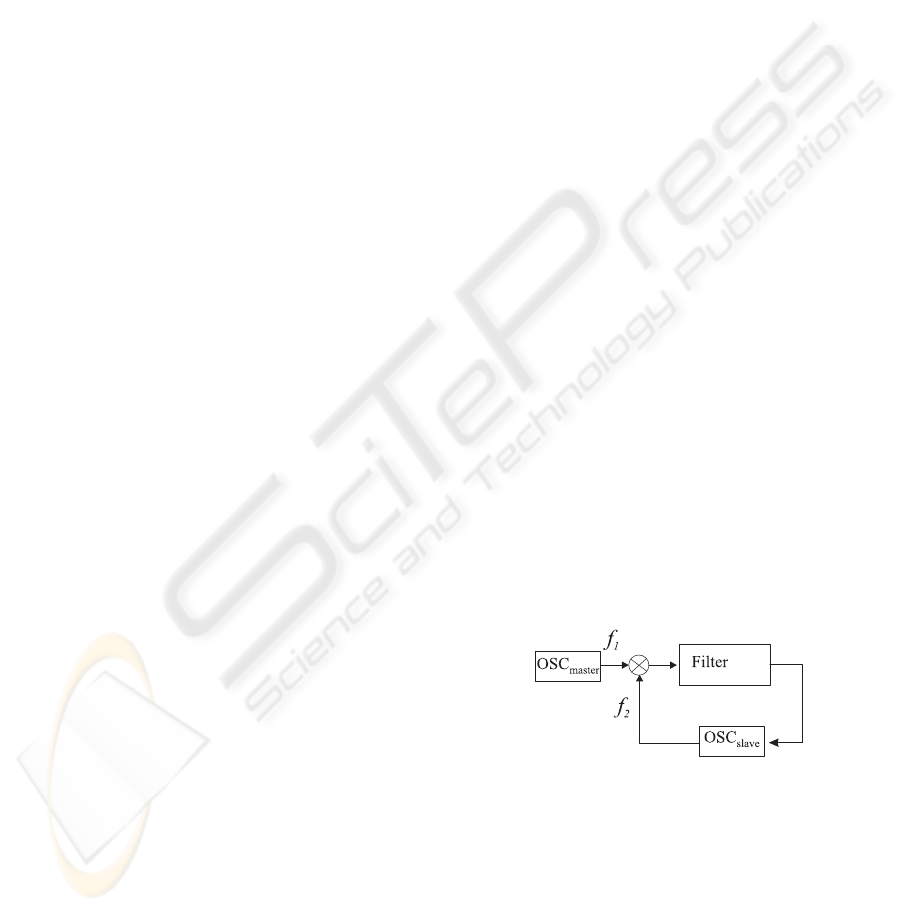
Figure 7: Costas loop.
4 COSTAS LOOP
Consider now a block diagram of the Costas loop
(Fig. 7)
Here all denotations are the same as in Fig. 1, 90
o
– is a quadrature component. As before, we consider
here the case of the high-frequency harmonic and im-
pulse signals f
j
(t).
However together with the assumption that condi-
tions (2) and (4) are valid we assume also that (3) is
satisfied for the signal of the type (1) and the relation
|ω
1
(τ) − 2ω
2
(τ)| ≤ C
1
, ∀τ ∈ [0,T ], (23)
is valid for the signal of the type (5).
Applying the similar approach we can obtain dif-
ferential equation for the Costas loop, where
˙z = Az + bΨ(σ)
˙
σ = c
∗
z + ρΨ(σ).
(24)
Here A is a constant n ×n-matrix, b and c are con-
stant n-vectors, ρ is a number, Ψ(σ) is a 2π-periodic
function, satisfying the following relations
ρ = −2aL, W (p) = (2L)
−1
c
∗
(A − pI)
−1
b,
ψ(σ) =
1
8
A
2
1
A
2
2
sinσ −
ω
1
(0) − ω
2
(0)
L(a +W (0))
,
σ = 2θ
1
− 2θ
2
(in the case (1);
ψ(σ) = P(σ) −
ω
1
(0) − 2ω
2
(0)
2L(a +W (0))
,
P(σ) =
−
2
A
2
1
A
2
2
µ
1
+
2σ
π
,
σ
∈
[
0
,
π
]
− 2A
2
1
A
2
2
µ
1 −
2σ
π
, σ ∈ [−π, 0]
σ = θ
1
− 2θ
2
(in the case (5).
From the above equations it follows that for
deterministic (when the noise is lacking) description
of the Costas loops the conventional introduction
of additional filters turns out unnecessary. Here a
central filter plays their role.
REFERENCES
Abramovitch, D., 2002. Phase-Locked Loope A control
Centric. Tutorial, in the Proceedings of the 2002 ACC.
Aleksenko, A., 2004. Digital engineering, Unimedstyle.
Moscow. (in Russian)
Best Ronald E., 2003. Phase-Lock Loops: Design, Simula-
tion and Application, McGraw Hill, 5
ed
.
Egan, W.F., 2000. Frequency Synthesis by Phase Lock ,(2nd
ed.), John Wiley and Sons, 2
ed
.
Gardner F., 2005. Phase–lock techniques, John Wiley &
Sons, New York, 2
ed
.
Kroupa, V., 2003. Phase Lock Loops and Frequency Syn-
thesis, John Wiley & Sons.
Kung, S., 1988. VLSI Array Processors, Prentice Hall. New
York.
Lapsley, P., Bier, J., Shoham, A., Lee, E., 1997. DSP Pro-
cessor Fundamentals Architecture and Features, IEE
Press. New York.
Leonov, G., Reitmann, V., Smirnova, V., 1992. Nonlocal
Methods for Pendulum-Like Feedback Systems, Teub-
ner Verlagsgesselschaft. Stuttgart; Leipzig.
Leonov, G., Ponomarenko, D., Smirnova, V., 1996.
Frequency-Domain Methods for Nonlinear Analysis.
Theory and Applications, World Scientific. Singapore.
Leonov, G., Seledzhi, S., 2002. Phase locked loops in array
processors, Nevsky dialekt. St.Petersburg. (in Rus-
sian)
Lindsey, W., 1972, Sinchronization systems in communica-
tion and ontrol, Prentice-Hall. New Jersey.
Lindsey, W., Chie, C., 1981. A Survey of Digital Phase
Locked Loops. Proceedings of the IEEE.
Razavi, B., 2003. Phase-Locking in High-Performance Sys-
tems: From Devices to Architectures, John Wiley &
Sons.
Smith, S., 1999. The Scientist and Engineers Guide to Dig-
ital Dignal Processing, California Technical Publish-
ing. San Diego.
Solonina, A., Ulahovich, D., Jakovlev, L., 2000. The Mo-
torola Digital Signal Processors. BHV, St. Petersburg.
(in Russian)
Ugrumov, E., 2000. Digital engineering, BHV,
St.Petersburg. (in Russian)
Viterbi, A., 1966. Principles of coherent communications,
McGraw-Hill. New York.
ICINCO 2008 - International Conference on Informatics in Control, Automation and Robotics
118
