
IDENTIFICATION OF THE DYNAMIC PARAMETERS OF THE C5
PARALLEL ROBOT
B. Achili
∗+
, B. Daachi
∗
, Y. Amirat
∗
and A. Ali-Cherif
+
+
Laboratoire d’Informatique Avanc´ee de Saint Denis, 2 rue de la libert´e, 93526 Saint Denis Cedex, France
∗
Laboratoire Images, Signaux et Syst`emes intelligents, 122-124 rue Paul Armangot, 94400 Vitry/seine, France
Keywords:
Identification, Parallel Robot, Least Squares Method, Cross validation.
Abstract:
This paper deals with the experimental identification of the dynamic parameters of the C5 parallel robot.
The inverse dynamic model of the robot is formulated under the form of linear equation with respect to the
dynamic parameters. Moreover, a heuristic procedure for finding the exciting trajectory has been conducted.
This trajectory is based on Fourier series whose coefficients are determined by using a heuristic method.
The least squares method has been applied to solve an over-determined linear system which is obtained by
sampling the dynamic model along the exciting trajectory. The experimental results show the effectiveness of
the identification procedure.
1 INTRODUCTION
A parallel architecture is a closed-loop mechanism
in which the end-effector (mobile platform) is con-
nected to the base by at least two independent kine-
matic chains. The pioneering works in this field are
those of Stewart who proposed in 1965 a parallel plat-
form with 6 DOF. Since then, several authors have
proposed a large variety of designs and studies. Paral-
lel architectures were first used for buildingflight sim-
ulators and tire testers. Since then, they were used in
other applications like the handling of heavy objects
with great accelerations, or the assembly of parts re-
quiring high precision. More recently, parallel robots
appeared in the medical field . The latter requires the
design of very precise parallel machines performing
in a limited workspace
Because of their structure, serial robots have lim-
ited dynamic performances. In the other hand, due to
their reducted inertia, parallel robots allow for the re-
duction of coupling dynamic effects and consequently
to better dynamic performance.
In the literature, several techniques were proposed
for the identification of dynamic parameters of robot.
A CAD method based on identifying inertia param-
eters is proposed in (An et al, 85). Usually these
methods lead to an unsufficientprecision of inertia pa-
rameters estimation and do not allow for the determi-
nation of other dynamic parameters (viscous friction,
coulomb friction). For better results, an estimation of
the whole dynamic parameters of the assembled robot
is required.
The identification procedure consists usually of
four main steps: (1) Calculation of an identifiable dy-
namic model, (2) Generation of the optimized excita-
tion trajectory, (3) Estimation of the dynamic parame-
ters, and finally (4) Validation of the obtained model.
The first step consists of calculating the minimal
set of dynamic parameters to be identified ( set of base
parameters). This set can be computed by using the
QR decomposition of observation matrix (Gautier,
91). In the second step, the optimal exciting trajec-
tory is calculated in order to guarantee the relevance
of the measured data. This step includes the choice of
an optimization criterion.
The third step consists of estimating the dy-
namic parameters from the measured data. Least
squares method is one of the most widely used es-
timation method. It consists of solving an over-
determined linear system (Janot, 07). An improve-
ment over the classical LS method is the use of a
Weighted Least Squares (WLS) estimator, (Renaud et
al, 06). Another approach is the Maximum Likeli-
hood Estimator(MLE) whose principle assumes that
the true parametric model is known exactly (Swevers
et al, 97). Other estimators like the ellipsoidal algo-
rithm or the interval analysis (Poignet et al, 03) have
been proposed in the literature.
The fourth step of identification procedure con-
sists of validating the identified dynamic model. In
67
Achili B., Daachi B., Amirat Y. and Ali-Cherif A. (2008).
IDENTIFICATION OF THE DYNAMIC PARAMETERS OF THE C5 PARALLEL ROBOT.
In Proceedings of the Fifth International Conference on Informatics in Control, Automation and Robotics - RA, pages 67-70
DOI: 10.5220/0001487300670070
Copyright
c
SciTePress
most cases, this is realized by comparing the predicted
and the measured torques for a trajectory which is dif-
ferent from the exciting trajectory.
In this paper we present the identification of dy-
namic parameters of the 6 DOF parallel robot with C5
joints. First, the dynamic model is expressed as a lin-
ear relation with respect to the dynamic parameters.
The parameters are estimated by the classical tech-
nique of least squares solving an overdetermined lin-
ear system obtained from a sampling of the dynamic
model, along the exciting trajectory.
The paper is organized in four sections. First one
describes the mechanical architecture of the C5 par-
allel robot. Second section presents the inverse dy-
namic model of the robot. Section 3 presents an esti-
mation of the dynamic parameters of the robot. Cal-
culation of the exciting trajectory along with the data
filtering procedure are developed in section 4. Fifth
section is dedicated to the presentation and analysis
of the experimental results including the cross valida-
tion procedure. Finally, a conclusion and some per-
spectives are given in the last section.
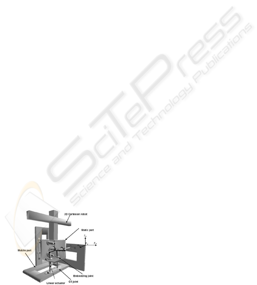
2 DESCRIPTION OF THE C5
PARALLEL ROBOT
The C5 parallel robot consists of a static part and a
mobile part connected together by six actuated links.
Each segment is embedded to the static part at point
A
i
and linked to the mobile part through a spherical
joint attached to two crossed sliding plates at point B
i
(Fig. 1).
Theoretical study concerning this architecture has
been presented in the literature. The C5 links paral-
lel robot is equipped with six linear actuators; each of
them is driven by a DC motor. Each motor drives a
ball and screw arrangement. The position measure-
ments are obtained from six incremental encoders,
which are tied to the DC motors.
Figure 1: Parallel robot.
3 MODELING OF THE C5 ROBOT
3.1 Inverse Dynamic Model
The inverse dynamic model of the C5 parallel robot is
given in (Khalil et al, 04):
To solve our identification problem, we rewrite the
inverse dynamic model to make it linear with respect
to dynamic parameters (Poignet et al, 02). The dy-
namic model is rewritten then as follows:
Γ = D(ω
p
,
˙
ω
p
,
˙
V
p
,q, ˙q, ¨q) X
s
(1)
with
• Γ : (6× 1) torque vector
• D : (6× 34) observation matrix
• X
s
: (34× 1) standard parameters vector:
X
s
= (X
s1
X
s2
X
s3
X
s4
X
s5
)
T
X
s1
= (M
1
M
2
M
3
M
4
M
5
M
6
M
p
)
X
s2
= (XX XY XZ YY YZ ZZ MX MY MZ)
X
s3
= (I
a1
I
a2
I
a3
I
a4
I
a5
I
a6
)
X
s4
= (F
v1
F
v2
F
v3
F
v4
F
v5
F
v6
)
X
s5
= (F
s1
F
s2
F
s3
F
s4
F
s5
F
s6
)
4 DYNAMIC PARAMETERS
IDENTIFICATION
For the purpose of dynamic parameters identification,
we use the formulation given in (Janot et al, 07). The
principle of identification consists in sampling the in-
verse dynamic model of the robot with respect to
the base parameters, obtained by QR decomposition
(Gautier, 91) along the exciting trajectory. A filtering
process is applied to the measured data in order to ob-
tain a good estimation of dynamic parameters. This
technique allows us to obtain an over-determined lin-
ear system of full rank.
5 EXCITING TRAJECTORY
CALCULATION
The quality of the exciting trajectory can be evaluated
through a good condition number of the regressor
matrix. The calculation of this trajectory can be
done by nonlinear optimization. In our case, we
used an exciting trajectory based on Fourier series
(Swevers et al, 91). For each segment j ( j = 1, 2, ...6),
ICINCO 2008 - International Conference on Informatics in Control, Automation and Robotics
68
the position q
j
can be written as follows:
q
j
(t) = q
j,0
+
M
∑
k=1
(a
j,k
sin(kω
f
t) + (b
j,k
cos(kω
f
t))
(2)
with
• ω
f
the fundamental pulsation of the finite Fourier
series.
• t the time.
• a
j,k
and b
j,k
(k = 1,...5) the amplitudes of sine
and cosine functions
• q
j,0
is the initial value of the position trajectory.
In order to excite the robot in the bandwidth of the
position closed loop, f
dyn
< 2 Hz , we have chosen the
fundamental frequency of trajectories equal to 0.1Hz
and the number of harmonics k = 5.
As the number of Fourier series coefficients is
high, it is difficult to determine them by a nonlinear
optimization. For this reason, we calculate these co-
efficients in a heuristic way. The calculation of these
parameters is based on the motion constraints which
are imposed by physical limitations of robot. These
constraints can be expressed as follows:
−0.05m < q
j
(α) < +0.05m (3)
−0.1m/s < ˙q
j
(α) < +0.1m/s (4)
−0.5m/s
2
< ¨q
j
(α) < +0.5m/s
2
(5)
Where:
Vector α includes the trajectory parameters q
j,0
,
a
j,k
and b
j,k
.
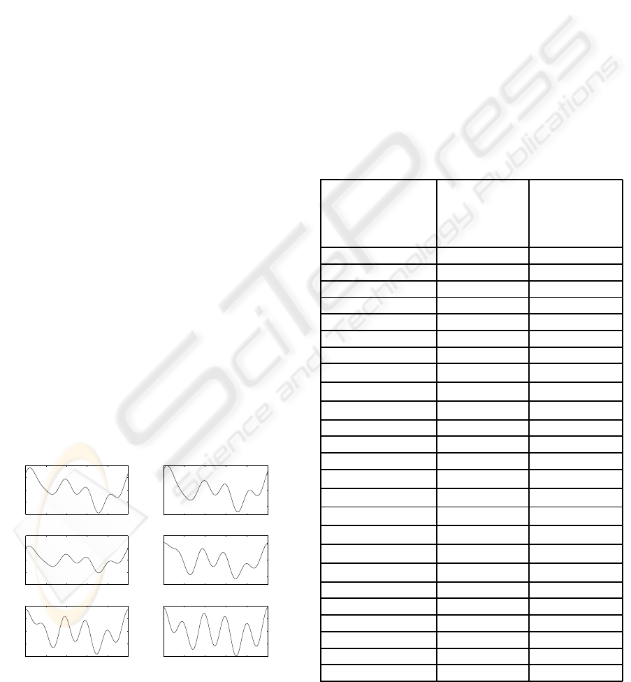
The heuristic approach allows us to find the excit-
ing trajectories shown in Fig. 2.
0 2000 4000 6000 8000 10000
−0.04
−0.02
0
0.02
0.04
Time [ms]
joint q1 [m]
0 2000 4000 6000 8000 10000
−0.02
0
0.02
Time [ms]
joint q2 [m]
0 2000 4000 6000 8000 10000
−0.04
−0.02
0
0.02
0.04
Time [ms]
joint q3 [m]
0 2000 4000 6000 8000 10000
−0.02
0
0.02
Time [ms]
joint q4 [m]
0 2000 4000 6000 8000 10000
−0.04
−0.02
0
0.02
0.04
Time [ms]
joint q5 [m]
0 2000 4000 6000 8000 10000
−0.04
−0.02
0
0.02
0.04
Time [ms]
joint q6 [m]
Figure 2: Exciting trajectories.
5.1 Data Filtering
For a good estimation of the dynamic parameters, the
measurementssignals need to be filtered . So the posi-
tion is filtered by the 4
th
order Butterworth filter. The
vector Y and each column of matrix W are filtered by
the 8
th
order Tchebychev filter and are resampled at
lower rate in order to reject the high frequency ripples
of the measured torques. The computation of joint ve-
locities and accelerations is made by using the central
difference algorithm in order to avoid any distortion
of phase and amplitude.
6 EXPERIMENTAL RESULTS
The table given in Fig. 3 shows the estimated base
parameters. The relative standard deviations are also
given.
parameters
identified
values
ˆ
X
relative
standard
deviations
%σ
ˆ
X jr
M
1
+ I
a1
(kg) 0.5435 7.0629
M
2
+ I
a2
(kg) 0.4075 11.3082
M
3
+ I
a3
(kg) 0.5436 7.0617
M
4
+ I
a4
(kg) 0.5909 6.7516
M
5
+ I
a5
(kg) 0.4909 8.8692
M
6
+ I
a6
(kg) 0.5718 6.7108
M
p
(kg) 8.2652 9.6980
XX(kg.m
2
) 0.1035 1.7892
YY(kg.m
2
) 0.2124 5.8701
ZZ(kg.m
2
) 0.0178 7.0021
MX(kg.m) 7.5925 2.0799
MY(kg.m) -1.8212 8.6681
MZ(kg.m) 21.2650 16.1002
F
v1
(N.m.s.rad
−1
) 8.8464 2.0209
F
v2
(N.m.s.rad
−1
) 7.9940 2.2183
F
v3
(N.m.s.rad
−1
) 8.7253 2.1198
F
v4
(N.m.s.rad
−1
) 7.5517 2.2366
F
v5
(N.m.s.rad
−1
) 8.1706 2.2777
F
v6
(N.m.s.rad
−1
) 8.7312 2.1182
F
s1
(N.m) 0.5034 5.1484
F
s2
(N.m) 0.3424 7.4246
F
s3
(N.m) 0.2344 9.3723
F
s4
(N.m) 0.2705 8.3329
F
s5
(N.m) 0.1753 13.1492
F
s6
(N.m) 0.2335 9.4081
Figure 3: Identified parameters.
IDENTIFICATION OF THE DYNAMIC PARAMETERS OF THE C5 PARALLEL ROBOT
69
Note that the dynamic parameters present in most
cases a relative standard deviation lower than 10%,
which represents a good estimation. However the rel-
ative standard deviation of the parameters MZ, and
F
S5
is higher than 10%. This deviation is due to me-
chanical constraints, consequently, we conclude that
the obtained results are encouraging and we can state
that these identification results are globally accept-
able.
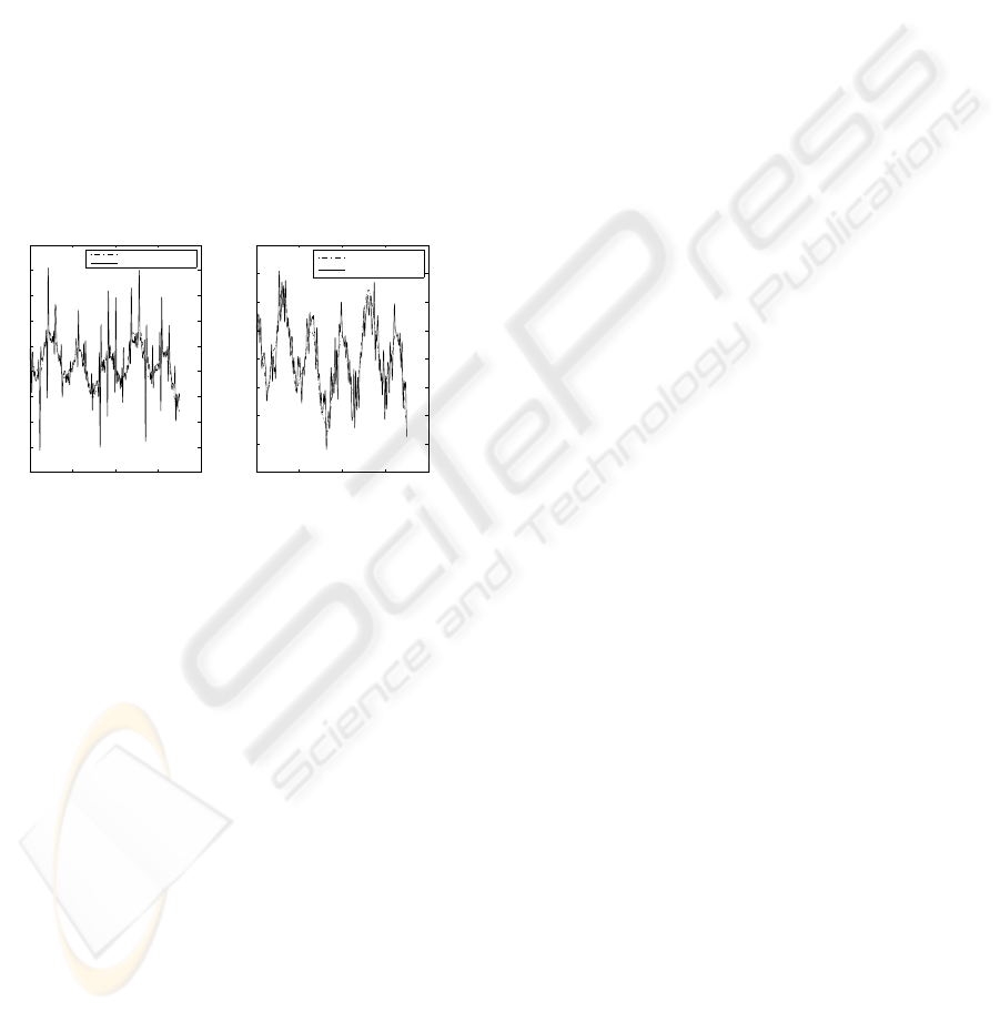
In order to validate the estimated dynamic param-
eters, we proceed to a cross validation which con-
sists in comparing the measured torques with those
obtained by the inverse dynamic model with the iden-
tified parameters. The trajectory which is usedfor this
validation has not been used previously for the iden-
tification. Figure 4 show the results of this validation.
For the others axis, we have also obtained the same
ting than figure 4
0 1000 2000 3000 4000
−8
−6
−4
−2
0
2
4
6
8
10
Time [ms]
Torque 1 [N.m]
0 1000 2000 3000 4000
−4
−3
−2
−1
0
1
2
3
4
Time [ms]
Torque 2 [N.m]
Estimated torque 2
Measured torque 2
Estimated torque 1
Measured torque 1
Figure 4: Estimated and measured torque for the joints 1
and 2.
Note that the calculated torques using the inverse
dynamic model with the estimated parameters are
close to those measured on the robot. Consequently,
one can conclude that the estimation of the dynamic
parameters, using the least squares method is valid.
7 CONCLUSIONS
In this paper, we identified the physical parameters
of the C5 parallel robot. The identification is based
on the least squares method. The application of this
identification method uses an exciting trajectory cal-
culated from a heuristic approach. To validate the
identified parameters, we considered another trajec-
tory different from that used in identification. The
cross validation enables us to conclude with the ef-
fectiveness of the considered identification. In short
term of our project, we propose to include the joint
elasticity, which is the major source of flexibility in
many practical applications.
REFERENCES
Swevers J., Ganseman C., Bilgin D., De Schutter J., Van
Brussel H., 1997. Optimal robot excitation and identi-
fication. IEEE Transactions on Robotics and Automa-
tion, 13(5):730–740.
Renaud, P., Vivas, A., Andreff, A., Poignet, P., 2006. Mar-
tinet, P., Pierrot, F., Company, O., Kinematic and dy-
namic identification of parallel mechanisms, In Con-
rol Engineering Practice 14, pp1099 - 1109.
Poignet, P., Ramdani, N., Vivas, A., 2003. Robust estima-
tion of parallel robot dynamic parameters with inter-
val analysis, Proceedings of the 42nd IEEE Confer-
ence on Decision and Control, pp. 6503-6508, Maui,
Hawaii, USA.
Khalil, W., Ibrahim, O., 2004. General Solution for the Dy-
namic Modeling of Parallel Robots, lnternational Con-
ference on Robotics & Automation, New Orleans, LA.
Gautier, M., Poignet, P., 2002. Identification en boucle
ferm´ee par mod`ele inverse des param`etres physiques
de syst`emes m´ecatroniques, Journal Eurepeen des
Syst`emes Automatis´es,36:465-480.
Gautier M., 1991. Numerical calculation of the base inertial
parameters, Journal of Robotics Systems, Vol. 8, No.
4, pp. 485-506.
An, C. H., Atkenson, C. G., Hollerbach, J. H., 1985. Es-
timation of inertial parameters of rigid body links of
manipulators, Proceedings of the 24th Conference on
Decision and control, pp. 990-995.
Janot, A., Bidard, C., Gosselin, F., Gautier, M., Keller, D.,
Perrot, Y., 2007. Modeling and Identification of a 3
DOF Haptic Interface,IEEE International Conference
on Robotics and Automation Roma, Italy, pp 4949-
4955
ICINCO 2008 - International Conference on Informatics in Control, Automation and Robotics
70
