
TELECONTROL PLATFORM
Telecontrol Platform for Industrial Installations
Eduardo J. Moya, Oscar Calvo, José María Pérez, José Ramón Janeiro and David García
Fundación CARTIF, Parque Tecnológico de Boecillo, Parcela 205, 47151 Boecillo, Valladolid, Spain
Keywords: GSM modem, analogical modem, PLC, SCADA, monitoring, Industrial Process.
Abstract: This article explains the telecontrol platform for industrial installations developed by CARTIF Foundation.
Using this system it will be able to send control orders and receive notification of alarms from the PLC
thanks to SMS (Short Messages System) messages which use GSM technology. In case of requiring a
greater flow of data it will use telephone line combined with MODBUS protocol. All this will enable us to
monitor and control any industrial installation with a very low cost. Copyright © 2007.
1 INTRODUCTION
The possibility of remote connections with industrial
processes can represent significant savings of time
and money for companies. In fact, you can control
and monitor equipments, update the software or
locate faults regardless of equipment location with a
simple remote connection.
These monitoring tasks can be carried out with
conventional technologies, as GSM network or
switched telephone network, (International
Engineering Consortium, 2007) which have been
installed for many years. These systems are
reappearing in industrial applications thanks to its
low cost and the broad range of possibilities offered
By using of these technologies (GeneralLynx,
2007), CARTIF Foundation has developed a
monitoring system based on GSM modems and
analogical ones that allow us to monitor and modify
variables of processes controlled by SIEMENS S7-
200 automatisms.
The article is organized as follows. In Section 2
we explain the first part of this project that consisted
in creating a system capable of controlling and
monitoring a process through SMS messaging. In
Section 3 we expose the second part of this project.
In this case we use an analogical modem to link PLC
and SCADA. In Section 4 we will explain a practical
case of the combined use of the library SMS and
communication via RTC modem. Finally
conclusions and open issues for future research are
discussed in Section 5.
2 MONITORING OF PROCESSES
USING GSM TECHNOLOGY
In the case we're dealing with we’ll use the GSM
network, which will allow us to send simple control
commands between a cellular and a PLC from any
place as long as we have enough coverage; this
system requires only a GSM modem and a SIM card
which are very cheap.
In this section we’ll explain the library called
SMS developed by CARTIF Foundation. This
library has been developed to be used with a
programmable Siemens PLC although similar
developments can be performed to be used with
other brands as Telemecanique, Omron or Allen-
Bradley.
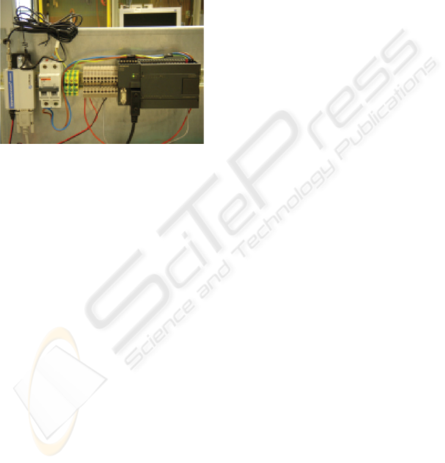
2.1 Elements of the System
CARTIF Foundation uses mainly programmable
PLCs of Siemens or Telemecanique. We decided to
develop SMS library to be used with a low-mid
range Siemens PLC. In this way, the automatism
that has been selected is a S7-200. Developing this
library for the S7-200, subsequent developments in
other PLC´s will be able to be conducted in a very
similar way.
Besides that it will be needed a RS 232/PPI
Multi-Master cable because the ports of Siemens S7-
200 series are RS-485 and GSM modems usually
have RS-232.
The third item of the system is a GSM modem.
81
J. Moya E., Calvo O., María Pérez J., Ramón Janeiro J. and García D. (2008).
TELECONTROL PLATFORM - Telecontrol Platform for Industrial Installations.
In Proceedings of the Fifth International Conference on Informatics in Control, Automation and Robotics - RA, pages 81-86
DOI: 10.5220/0001491300810086
Copyright
c
SciTePress
At first it was wanted to develop a library that would
be independent of the brand and model of GSM
modem, but it wasn’t possible because each brand
have different responses to the commands that are
sent to it. In order to simplify the design of the
library it will be used a generic one, GSM/GPRS
Wavecom Fastrack (Fastrack Modem M1306B,
2007).
Figure 1: PLC & GSM modem.
2.2 Characteristics of SMS Library
SMS library has as basic functions the reception and
sending SMS messages, always besides their
treatment. The great advantage is that
communication with modems is standardized
through the use of AT commands (AT Commands
Interface Guide, 2007). AT commands are just
coded instructions for communication between a
device and a modem. As we said before although the
instructions that are sent to modems are standardized
through the AT commands, the modems responses
are not. This causes the library not to be valid for all
GSM modems, although its adaptation to other
models is very simple.
2.2.1 AT Commands
The commands AT used in the library are: ATE0,
AT+CPIN ?, AT+CPIN = "Nº PIN", AT+CMGF =
1, AT+CSMP = 17,167,0,0, AT+CREG ?,
AT+CPMS = "SM", AT+CMGS = "PHONE
NUMBER", AT+CMGR = X, AT+CMGD = X.
2.2.2 Library Functions
The library functions are:
Sending SMS.
Periodical control of coverage.
Output of error.
Automatic blocking in case of entering a
wrong PIN.
Reception of SMS
Elimination SPAM.
Automatic Clearing of the read SMS.
Permits of access.
Treatment automatic SMS.
Treatment of SMS by the user.
Size in program memory: 4.5Kb
Size in data memory: 490 bytes.
2.3 Compatible SMS
For the use of library SMS is only necessary to have
a mobile phone (Moya, 2007). You can send SMS of
two types:
2.3.1 SPECIFIC Messages
These messages are customized for an installation in
concrete. In this case, the library SMS returns the
text message received and is the programmer of PLC
who is responsible to deal with it. These messages
have the following format:
“PERS” “STOP MOTOR 1”
In addition, the programmer of PLC can send
SMS of notification of alarms or as a response or
acknowledgement to an SMS received, being the
format of these messages to choice of the controller.
2.3.2 STANDARD Messages
These messages are called standard because they are
not specific of an installation. They are treated
directly by the library SMS and in the event that it
will have configured, send an acknowledgement of
receipt.
This kind of message has the following format in
the case of messages of modification of variables:
“ESTA”“SYMBOL”“ADDRESS”“OPERATION”
or in case of messages of consultation
“ESTA” “SYMBOL” “ADDRESS” “?”
Once received a message of consultation, the
response is sent automatically, and in the case of
modifications of variables is sent an
acknowledgement if it has been configured.
In this kind of messages, “SYMBOL”
corresponds with the type of variable (V, VB, VW,
VD and VR). The “ADDRESS” corresponds with
the memory address (1000.1). The “OPERATION”
ICINCO 2008 - International Conference on Informatics in Control, Automation and Robotics
82
field corresponds with the value to write in the
direction of memory and in the case of "?" means
that it is a consultation of the value of the data
located in this address.
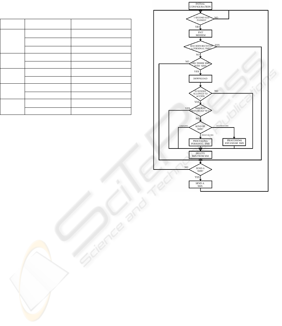
Table 1: Operations performed by SMS.
DATA OPERATION DESCRIPTION
1 Force a bit to be ON
0 Force a bit to be OFF
V
?
Ask about a bit status
VALUE Change a byte
VB
?
Ask about a byte value
VALUE Change a word
VW
? Ask about a word value
VALUE Change a integer
VD
? Ask about a integer value
VALUE Change a real
VR
? Ask about a real value
2.4 Program Flow
As is shown in the flow diagram (figure 2), firstly a
start stage is done in which, among other things, it’s
checked whether the PIN code is entered (if it’s not,
it will be entered) and the existence of coverage is
verified.
The following step is to check if there are
messages in the SIM card. In the case that there are
any, the message is downloaded from the SIM card
to a reserved area in the PLC. In the case that there
are not, it would go to the stage for sending SMS
from which it would send a message in the case that
the user program required so. In the next step it’s
checked whether the SMS sender’s telephone has
permission to access to the control and modification
of variables. This eliminates directly SPAM and
telephones without access permission.
In the next step it’s verified that the text message
has not been read in previous cycles. In the case that
the telephone does not have permission to access or
the SMS has been read, the message is deleted. In
the case that the SMS has not been deleted in the
previous stage, it is checked whether the type of
message is: “ESTANDAR”, “SPECIFIC” or none of
the two types. In the last case it is removed.
When it is received a “ESTA” SMS, it is dealed
by the library SMS whether it is a monitoring
message or if it is a control message.
If it’s a message "PERS" type it is returned by
the subroutine SMS to the main programme and it is
the programmer the responsible for its dealing.
Then, once dealed, the SMS is removed from the
GSM modem’s SIM memory. In the next step
SMS’s are sent both of the acknowledgement,
responses to consultations or notification of alarms.
Figure 2: SMS program flow.
3 SUPERVISION & CONTROL
OF PROCESS THROUGH
ANALOGICAL MODEMS
In recent decades, the improvement of
communication systems has caused a change in the
form that the society sees the world. These
improvements have narrowed the gap between the
different points of the planet so any event can be
known anywhere almost instantaneously.
Communications via telephone line and its
application to computer systems through the
modems have largely contributed to this.
The great coverage of the conventional telephone
network enables an almost immediate connection
between two computers if modems are used, and if
it’s extended to the industrial area it will provide us
a cheap and effective method of controlling a
process without the need for large disbursements.
TELECONTROL PLATFORM - Telecontrol Platform for Industrial Installations
83
3.1 Items of the System
3.1.1 PLC
Like for communication via GSM the PLC that we’ll
use will be a S7-200, although once set the
foundations of the system, it can be carried out in
other brands’s PLC by introducing small changes.
3.1.2 Analogical MODEM
The Modem chosen is a module for expansion of S7-
200. It does not need any library and its
configuration is very simple, thanks to the assistant
of the PLC’s programming tool. It works in slave
mode, and it uses MODBUS protocol to
communicate with the PC, which will play a master
role in our supervision system (Jiménez, 2007).
3.1.3 Personal Computer
The master of the system is a PC. This has a Modem
to communicate with the Modem EM241 via the
telephone line. To treat the data being received, a
software application in Visual Basic has been
scheduled, which transforms the MODBUS strings
characters in data that can be displayed in a SCADA
also scheduled in Visual Basic (Janeiro, 2006).
3.2 System Characteristics
3.2.1 Description of Modbus RTU Protocol
Once the connection between the modem local
modem and remote modem connected to the PLC is
established, we must choose a protocol that helps us
to exchange data between the PC (MASTER) and
the PLC that controls our process (SLAVE).
In our case the protocol which we’ll use will be
MODBUS RTU, very used in the industry for
communications via modem.
The controllers communicate by means of a
master-slave technique, in which only one device
(master) may start transactions. The other devices
(slaves) respond by supplying the master the data
requested, or carrying out the action requested in the
petition. Among the master devices typical central
processors and programming panels are included.
Typical slaves are the PLC’s.
3.2.2 The Query-Response Cycle
Query: The function code in the petition indicates
the slave device directing the type of action to
perform. The bytes of data contain any additional
information that the slave will need to carry out the
function. The data field must contain the information
to indicate the slave in what registration it should
begin and how many has to read. The error
verification field provides a method for the slave to
validate the integrity of the contents of the received
message.
Response: If the slave develops a normal response,
the function code content in the response is a replica
of the function code sent in the petition. The bytes of
data contain data collected by the slave, such as
values of registers or states. If an error occurs, the
function code content in the answer is different from
the function code sent in the petition, to indicate that
the answer is a response of error and the bytes of
data contain a code that describes the error. The
verification of error field allows the master to
confirm that the contents of the message are valid.
3.2.3 Queries Implemented by the
Application
Modbus is a protocol developed by Modicon for its
range of PLCs. Siemens, particularly S7-200, has
implemented libraries, which introduced in the
program code, allow to use it. In our case, the
EM241 module has them included, for what it’s not
necessary to modify anything in the PLC’s
programme.
Table 2: Modbus operations implemented by SIEMENS.
FUNCTION DESCRIPTION
1
Read coil status
2
Read input status
3
Read holding registers
4
Read input registers
5
Force single coil
6
Preset single register
15
Force multiple coils
16
Preset multiple registers
Despite that Modbus incorporates a wide variety
of functions, SIEMENS only has 8 implemented
which are those indicated in the table 2.
These operations act on bits in the case of inputs
and outputs, or in words if it is variables in PLC
memory. In the case of desiring to use different
variable sizes, as double words, bits of PLC
memory, etc, it must be done from these functions.
The application which has been developed, has
taken into account this problem and has been
programmed to allow the following requests:
Read and write digital outputs.
Read analogical inputs.
ICINCO 2008 - International Conference on Informatics in Control, Automation and Robotics
84
Read and write integers.
Read and write double integers.
Read and write real numbers.
Read and write bits from V memory.
The PLC responds by strings MODBUS RTU in
hexadecimal that must be decoded.
3.2.4 AT Commands used
As in the case of communication using a GSM link,
it has been needed AT commandsm: AT, ATE0,
ATS30=time (s), ATDnumber, ATH.
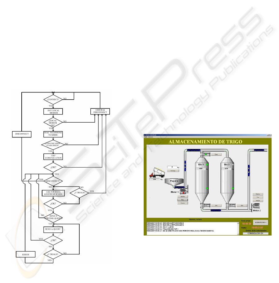
3.2.5 Application Flow
Before establishing any communication it must be
verified that the configuration of PC-Modem is
correct. If this is so it can proceed to dial the
telephone number of the modem connected to the
PLC. In the case of being the line occupied or not to
establish the connection it will generate a message
informing about what is happening.
Figure 3: Program flow.
After connecting with the PLC test strings will
be sent to see check that the communication is good.
If everything is OK application will send petitions to
the PLC with the frequency of refresh assigned by
the user. The times of refresh can vary, from 2
seconds. Application must send petitions to the PLC,
receive the responses from it, decode them and
display in a screen through the SCADA. In addition
to this, it will have to detect the communication
errors that may occur.
On the other hand, it also takes into account the
possible delays that may result from a wrong
function of the modem, temporary disconnections of
the line, etc. If these failure times are excessive, as
in the previous case, the Modem gets disconnect and
the cause is notified. In the case of wanting to
change a variable of the PLC, the SCADA
refreshing cycle is interrupted and the petition sent.
If the operation is carried out successfully it returns
to the routine of variable reading.
4 PRACTICAL APPLICATION
Now we will explain a practical case of the
combined use of the library SMS and
communication via RTC modem.
The case that we explain is a wheat storage and
dosage plan. The process is divided into two parts:
the part storage of wheat (Figure 4) consists of the
bunghole and the first of two silos, while the part
dosage of wheat (Figure 5) includes the last five
silos and a weight scale.
Figure 4: Storage of wheat.
The download of wheat from the truck is carried
out in the bunghole. To transfer the burden of wheat
from the entry deposit to one of the two storage silos
(Silo 1 or 2) the engine on the left must be on to
activate the endless screw and the buckets elevators
(horizontal and vertical displacement of wheat).
The wheat shall be deposited in Silo 1 or Silo 2,
depending on whether the upper chopping block in
Silo 1, is open or not. The wheat flow considered
TELECONTROL PLATFORM - Telecontrol Platform for Industrial Installations
85
when this transfer performed is 10 kg/s.
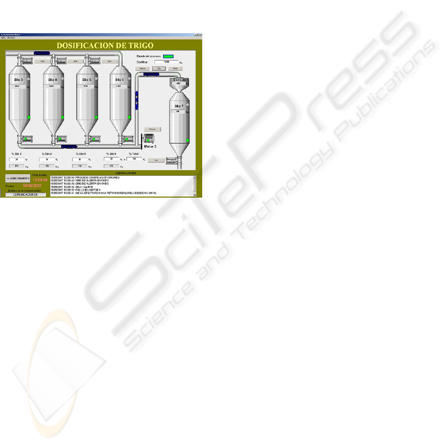
The process of dosage consists on four silos
(Silo 3, 4, 5 or 6) where different types of wheat are
stored and on silo 7, where the mixture composed by
wheats form Silos 3, 4, 5 or 6 is obtained. The
maximum capacity of all these silos is 10.000 Kg.
The flow of endless screws and the buckets elevators
is as maximum 50 kg/s. The wheat supply in Silos 3,
4, 5 or 6 comes from storage Silos 1 and 2 of. The
operator will be responsible for selecting the
destination of wheat from Silos 1 and 2 by
opening/closing the different upper chopping blocks
of Silos 3, 4, 5 or 6.
Figure 5: Dosage of wheat.
Apart from "ESTANDAR" SMS configured for
this installation, the following "SPECIFIC"
messages have been programmed:
Control: It can activate the dosage and stop it.
Consultations: It can make consultations such as
the weight of different silos, of the bunghole or of
the dosage. It can ask about the state of the engines,
as well as the state of the chopping blocks.
Maintenance: The alarm notifications have been
programmed: unloading a truck in the bunghole,
failure of any of the engines, filling of silos, and
failure in the dosage and notices that the dosage has
been completed.
To display the status of the process and the
changes that we are doing via SMS we use the
SCADA scheduled in Visual Basic, which uses the
RTC line to establish the communication with the
PLC.
5 CONCLUSIONS
The aim of this project was to make a system for
supervising processes that allowed remote control of
any installation in a simple and safe way but without
incurring big costs.
This platform has been focused to be used in
mid-range automatons such as the S7-200, because
this PLC is the most indicated to control the
processes that can be supervised by this system.
It has been tried to deal with the issue from two
fronts, through a wireless communication by GSM
Modems and on the other hand, a communication
through telephone line. The choice of one or another
depends on different factors such as: the location
and accessibility of the plant, means of
communication, level of automation, process
complexity, etc.
In general, it can be said that for all activities that
require an important exchange of data or/and a
constant supervision, it would be advisable the
implementation of an analogical modem
communication system.
In the future is planned to develop this platform
with other PLC brands like Telemecanique and
Omron.
ACKNOWLEDGEMENTS
This work was supported in part by “Programa de
Fomento de la Investigación Técnica para los
Centros Tecnológicos”, (PROFIT grant FIT 330220-
2005-138) from the Spanish Education and Culture
Ministry.
REFERENCES
AT Commands Interface Guide, <http://
www.rfsolutions.co.uk>, (in June 6, 2007).
Fastrack Modem M1306B User Guide, <http://
www.omniinstruments.co.uk>, (in June 6, 2007)
GeneraLynx. Remote supervision and control by WAP,
<http://www.euroines.com/down/DemoDoc/WapScad
a%20DD.pdf>, (in January 10, 2007)
International Engineering Consortium. Global System for
Mobile Communication, <http:www.iec.org/online/tu
torials/gsm/>, (in January 10, 2007)
Janeiro, J. R., 2006. Supervisión remota de procesos
industriales controlados por Autómatas Programables,
University of Valladolid. Spain, 1
nd
edition.
Jiménez, M., Comunicaciones Industriales, Protocolo
Modbus, <http:www.dte.upct.es>, (in June 6, 2007).
Moya, E., 2007. Control y mantenimiento de instalaciones
remotas. Wireless. Automática e Instrumentación, 384,
pp. 44-47.
ICINCO 2008 - International Conference on Informatics in Control, Automation and Robotics
86
