
AN APPROACH TO OBTAIN A PLC PROGRAM FROM A DEVS
MODEL
Hyeong T. Park, Kil Y. Seong, Suraj Dangol, Gi N. Wang and Sang C. Park
Department of Industrial Information & Systems Engineering, Ajou University, Korea
Keywords: Programmable Logic Controller(PLC), DEVS, Factory Automation, Simulation.
Abstract: Proposed in the paper is an approach to generate the PLC code from the Discrete Event System
Specification (DEVS) model. DEVS have been widely accepted to model the real system for the discrete
event system simulation. The objective of this paper is to generate PLC control code from the DEVS model.
To achieve it, this paper proposes two steps. First step is to convert the real system into the virtual model
using the ‘three-phase-modeling procedure’. In the second step, the obtained model is formalized with
DEVS formalism. The final model consists of different components, among them the State manager and the
Flow controller model plays vital role to generate PLC code. In this paper, proposed steps are described
with a work cell example.
1 INTRODUCTION
To survive and prosper in the modern manufacturing
era, a manufacturing company should be capable of
adapting reduced life cycle of products in a
continuously changing market place. Simulation is a
useful tool for manufacturers to adapt this kind of
rapidly changing market to design and analyze
complex systems that are difficult to model
analytically or mathematically (Choi, 2000).
Manufacturers who are using simulation can reduce
time to reach stable state of automated
manufacturing process by utilizing statistics, finding
bottlenecks, pointing out scheduling error etc... For
the simulation of manufacturing systems,
manufacturers have been using various simulation
languages, simulation software for example
ARENA, AutoMod. Most of traditional simulation
languages and softwares focus on the representation
of independent entity flows between processes; their
method is commonly referenced to as a transaction-
oriented approach. In this paper, we propose an
object-oriented approach that is based on the set of
object classes capable of modeling a behavior of
existing system components.
The object-oriented modeling (OOM) is a
modeling paradigm, that uses real world objects for
modeling and builds language independent design
organized around those objects (Rumbaugh, 1991).
Even though OOM has been widely known to be an
effective method for modeling complicated software
systems, very few researchers tried to apply the
OOM to design and simulate manufacturing system
software models. Based on the OOM paradigm,
different researchers have proposed various
modeling approaches despite the fact that they
express them in different ways with different
notations. For example, Choi et al. presented the JR-
net framework for modeling which is based on the
OOM paradigm of Rumbaugh et al., which is made
of three sub-models(an object model, functional
model, and dynamic model). Chen and Lu proposed
an object-oriented modeling methodology to model
production systems in terms of the Petri-nets, the
entity relationship diagram (ERD) and the IDEF0
(Chen, 1994). Virtual factory (VF) is also very
important concept to be considered in today’s
simulation environment. By using the OOM
paradigm, VF concept can be implemented
efficiently (Onosato, 1993).
Recently, Park (Park, 2005) proposed a ‘three-
phase-modeling framework’ for creating a virtual
model for an automated manufacturing system. This
paper employs the three-phase-modeling framework
of creating a virtual model, and the Discrete Event
System Specification(DEVS) (Zeigler, 1984) for
process modeling. The proposed virtual model
consists of four types of objects. The virtual device
model represents the static layout of devices. This
can be decomposed into the shell and core, which
87
T. Park H., Y. Seong K., Dangol S., N. Wang G. and C. Park S. (2008).
AN APPROACH TO OBTAIN A PLC PROGRAM FROM A DEVS MODEL.
In Proceedings of the Fifth International Conference on Informatics in Control, Automation and Robotics - RA, pages 87-93
DOI: 10.5220/0001492400870093
Copyright
c
SciTePress

encourages the reusability making possible to adapt
different system configurations. For the fidelity of
the virtual model, The Transfer handler model
handles a set of device-level command that mimics
the physical mechanism of a transfer. The Flow
controller model decides the firable transfers based
on decision variables that are determined by the
State manager model. The State manager model and
Flow controller model can be converted to PLC part.
After finishing the process modeling by employing
the three-phase-modeling framework, those two
models will be the control information for the
converting to PLC.
The overall structure of the paper is as follows.
Section 2 represents the brief explanation about the
PLC, and Section 3 is about the DEVS. The overall
approach to create manufacturing system model for
generation PLC code is described in Section 4.
Section 5 gives as example cell, which is observed
to find correlation between the PLC code and the
DEVS model in Section 6. Finally, Conclusion and
discussion is addressed in Section 7.
2 PROGRAMMABLE LOGIC
CONTROLLER (PLC)
The Programmable Logic Controller (PLC) is an
industrial computer used to control automated
processes in manufacturing (Parr, 1999). PLC is
designed for multiple inputs and outputs
arrangements, it detects process state data through
the sensing devices such as limit sensors, proximity
sensors or signals from the robots executes logics in
its memory and triggers the next command through
the actuator such as motor, solenoid valve or
command signal for the robots etc. PLC executes the
control logic programmed in different types of
languages. IEC published IEC 61131-3 to
standardize PLC languages including Ladder
diagram, Sequential Function Chart, Structured Text
and Function Block Diagram (Maslar, 1996).
Figure 1: The PLC code in the form of Ladder diagram.
3 DISCRETE EVENT SYSTEM
SPECIFICATION (DEVS)
DEVS formalism is introduced by Zeigler, which is
a theoretic formalism and it supplies a means of
modeling discrete event system in a modular,
hierarchical way. With this DEVS formalism, we
can perform modeling more easily and correctly by
dividing large system into segment models and
define the coupling between them. Formally, an
atomic model M is specified by a 7-tuple:
M = < X, S, Y,
δ
int,
δ
ext,
λ
,
t
a
>
X : input events set;
S : sequential states set;
Y : output events set;
δ
int
: SÆS : internal transition function;
δ
ext
: Q x X Æ S : external transition function
Q = { (s, e)|s ∈ S, 0 ≤
e
≤
t
a
(
s
)}
: total
state of M;
λ
: S->Y : output function;
t
a
: S
Æ
Real : time advance function:
The second form of the model, called a coupled
model, indicates how to couple several element
models together to form a new and bigger model.
Formally, a coupled model DN is defined as:
DN = < X, Y, M, EIC, EOC, IC, SELECT >
X : input events set;
Y : output events set;
M: set of all component models in DEVS;
EIC ∈ DN.IN x M.IN : external input coupling
relation;
EOC ∈ M.OUT x DN.OUT : external output
ICINCO 2008 - International Conference on Informatics in Control, Automation and Robotics
88

coupling relation;
IC ∈ M.OUT x M.IN : internal coupling relation;
SELECT : 2
M
- ø-> M : tie-breaking selector,
Where the extension .IN and .OUT represent the
input ports set and the output ports set of each
DEVS models.
4 APPROACH TO CREATE
MANUFACTURING SYSTEM
MODEL TO GENERATE PLC
CODE
To construct the automated process, the factory
designers have to consider the overall process
layout. After deciding skeletal layout, the process
cycle time is simulated by the discrete event system
software like ARENA or AutoMod. In this stage,
including the process cycle time and production
capability, the physical validity and efficiency of co-
working machines are also described. Simulation
and modeling software QUEST or IGRIP are used
for this purpose (Breuss, 2005).
Figure 2: Automated Factory construction procedure.
On the next step, the PLC code programming for
logical functioning is done without utilizing
information from previous discrete event systems
modeling. The gap between the high level
simulation of discrete event system and the low level
physical process control logic need to be bridged for
the utilization of process modeling and practical
simulation in terms of physical automated device
movement. This paper tries to find the bridge
between these two different simulation levels and
further describes automatic generation of PLC code
from the DEVS model.
In developing the DEVS model, the first thing
we have to do is to model the manufacturing system
by the three-phase-modeling framework (Park,
2005). The framework describes manufacturing
system modeling with 4 components; the Virtual
device model, the Transfer handler model, the State
manager model and the Flow controller model as
shown in Figure 3.
Figure 3: Outline of the virtual manufacturing model.
The Virtual device model shows the manufacturing
devices. It has input port to receive the action signal
and output port to send the work done signal. The
Transfer handler model handles the parts stream and
assisting resources (tools and pallets) between
devices. This approach focused on the physical
mechanism enabling the transfer than conventional
approaches. In reality, a transfer happens by the
combination of device-level command between co-
working devices (giving and taking devices). The
State manager model collects the state data of every
device. Whenever there is a state change of devices,
it will update the device states. Then, this
information will be delivered to the Flow controller
model as a decision variable. After getting the state
information from the State manager model, the Flow
controller model will decide firable transfer based on
the system state (decision variables).
AN APPROACH TO OBTAIN A PLC PROGRAM FROM A DEVS MODEL
89
For the implementation of the virtual
manufacturing system model, this paper employs the
Discrete Event Systems Specification (DEVS)
formalism, which supports the specification of
discrete event models in a hierarchical modular
manner. The formalism is highly compatible with
OOM for simulation. Under the DEVS formalism,
we need to specify two types of sub-models: (1) the
atomic model, the basic models, from which larger
ones are built and (2) the coupled model, how
atomic models are related in a hierarchical manner.
When the DEVS model is developed, both the
State manager atomic model for the process
monitoring and the Flow controller atomic model for
the actual control can be replaced the PLC part.
Namely, control part for the manufacturing cell.
Here is the goal of this paper.
5 DEVS MODELING OF A
SIMPLE CELL BASED ON THE
THREE-PHASE-MODELING
FRAMEWORK
In this Chapter, we will observe a small work cell
example. The work cell is modeled according to the
three-phase-modeling framework and converted to
the DEVS model like mentioned above. Finally, we
will compare the DEVS model and the PLC code to
find some meaningful bridge.
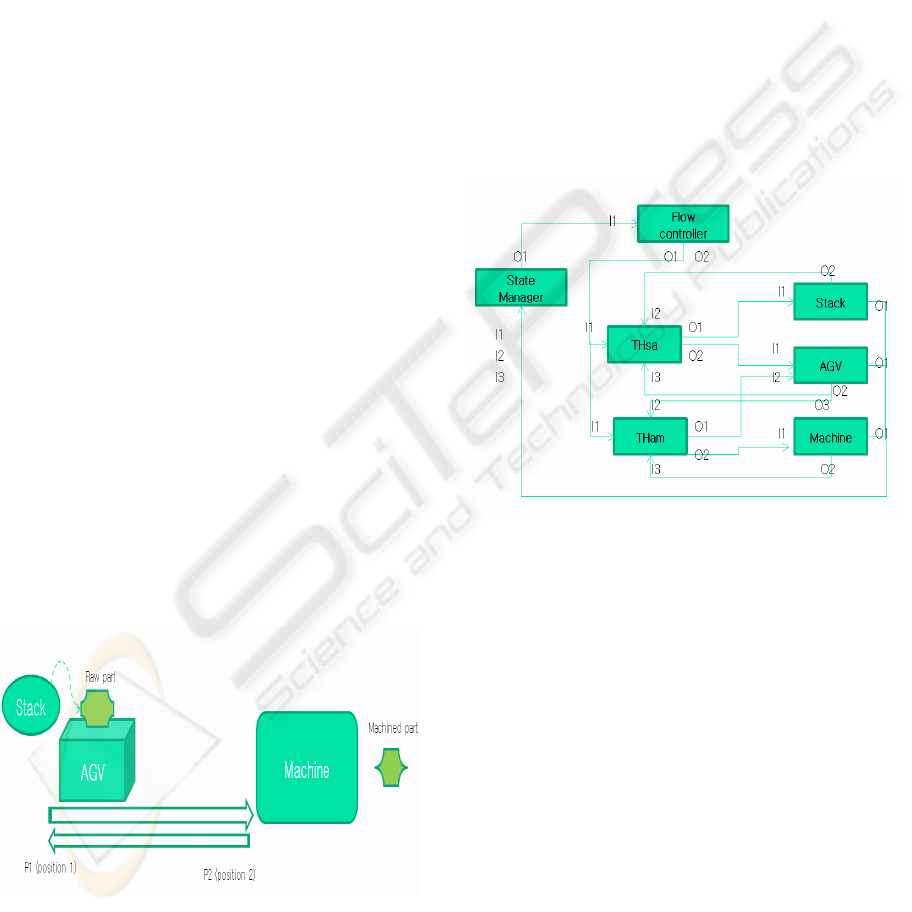
Figure 4 shows the small cell example. At first,
an entity is generated from the Stack, which will lay
on the AGV machine in P1, then AGV senses this
raw part and moves to the P2 for machining. When
machine detects the part arrival by the AGV, the
machine starts to operate.
Figure 4: Example cell.
When we consider this example cell in terms of
the three-phase-modeling framework, there are three
virtual device models; the stack model, the AGV
model and the machine model. The stack model
generates the raw part entity and places it on the
AGV for transfer. Until this point, the entity transfer
process is between the stack and the AGV virtual
device model as a result the transfer handler model
is created between the stack the AGV model.
Similarly, entity transferring between the AGV
model and the Machine happens. This transfer
handling model can be represented as THam. If there
is any state change among the virtual devices, the
changes are supposed to be reported to the State
manager model. The State manager model maintains
the decision variables in compliance with the
reported state changes of the virtual devices and the
Flow controller model will make a decision on
firable transfer based on the decision variables.
Figure 5 represents the constructed model about the
example cell.
Figure 5: Modeling of the example cell in the Park’s
methodology.
Once the modeling by means of the three-phase-
modeling framework is finished, second step is to
convert the model to the DEVS formalism. In this
example, every model is converted to the atomic
model and entire cell will be the coupled model that
is consist of all atomic models. Figure 6 is the
converted DEVS model example of AGV. In the
traditional implementation of discrete event system
simulation using DEVS, DEVSIM++ is a simulation
framework which realizes the DEVS formalism for
modeling and related abstract simulator concepts for
simulation, all in C++ (Kim, 1994). Through this
open source frame, we can develop the discrete
event system simulation engine easily. Once, both
the DEVS implementation and the simulation with
PLC control logic is done, we can achieve the
overall physical control simulator for automated
process.
ICINCO 2008 - International Conference on Informatics in Control, Automation and Robotics
90
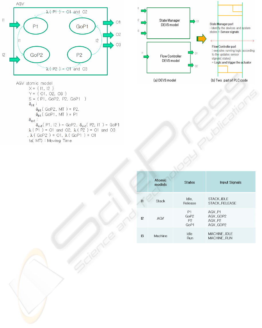
Figure 6: DEVS model of the AGV.
6 CORRELATION BETWEEN
THE PLC CODE AND THE
DEVS MODELS
For the auto generation of PLC code from the DEVS
model, we need to examine the PLC code of
example cell and the DEVS models, especially the
State manager and the Flow controller model.
In the manufacturing unit, PLC collects the
process state information through the sensors. These
sensor signals are referenced to decide next
command or operation. This task is done by the state
manager model in the modeled frame. The State
manager model detects every change in state of the
virtual device and then updates the decision
variables. Similar to PLC code, the Flow controller
model is supposed to have running logic that is kind
of combination of decision variables. As a result,
PLC code from the DEVS model can be divided into
two parts. One part is for updating the decision
variable from the signal of input port in the State
manager model. Another is for actual logic
composed of decision variables to fulfill the
intended process control.
Figure 7: Two part of PLC code.
In the front part, the State manager model
collects every state changes through the input port.
The one input port of example cell has different kind
of signal depend on the state. For example, the input
port I2 is the signal from the AGV and it has 4
different kinds of state signals. With the same way,
each input port of the State manager model has
multiple input signals like shown in Table 1.
Table 1: The States of Atomic models.
The memory structure in the PLC code can be
classified into three groups. The first group is input
memory which consists of input signal names and
the second group is the output memory consisting
output signal names and the last is the internal
memory which is used to maintain the signal
information of input or output and for temporary
numerical calculation. The name of input signal can
be determined with combination between the input
port and its state name. In this way, we can give a
name to all input signals.
As mentioned before, the flow controller model
reads the decision variables to execute next
command. Thus, we have to make decision variables
representing the process state as the internal
memory. As we did in the input variable for naming,
we can give decision variables’ name by putting the
AN APPROACH TO OBTAIN A PLC PROGRAM FROM A DEVS MODEL
91

‘On’ between the port name and the state name.
Then, this decision variable shows the port’s current
state is active condition. Once decision variables are
set, the Flow controller detects the firable output
signals from the set variables. Figure 8 show the
decision variables of each input of AGV model and
moving condition. To the AGV, the possible
condition to move from P1 to P2 is when the raw
part is on the AGV, AGV’s state is ‘GoP2’, and the
machine state is ‘Idle’ at the same time.
Figure 8: The triggering condition for AGV move.
As we have noticed for the case of the AGV
model, the other devices’ executing condition can be
derived. While the PLC code for the State manager
model part can be generated automatically with a
combination of decision variables, the flow
controller part is sometimes rather ambiguous. That
is because unlike the flow controller, DEVS model
is quite abstract and high level, the PLC part is very
specific control area. Even though, process system
designer can construct the DEVS model including
low level of PLC, normally DEVS modeling is not
fulfilled in this way. This aspect will be limitation or
designer’s choice in reference to PLC code auto
generation. The DEVS modeling here is done
specifically in mind of the PLC code generation of
the Flow Controller model part. Figure 9 illustrates
the two part of PLC code about the AGV from the
State manager and the Flow controller model. And
the Flow controller DEVS model for PLC code auto
generation with the simple work cell is shown in
Fig. 10.
7 DISSCUSSION AND
CONCLUSIONS
This paper presents the PLC code auto generation
methodology from the DEVS model. The PLC level
control logic is rather closed and unopened
engineering area while discrete event system
modeling and simulation is widely used to
Figure 9(a): PLC code from the State Manager model of
AGV model.
Figure 9(b): PLC code from the Flow Controller model of
AGV model
measure the process capacity. By using the discrete
event system simulation technique, the process or
overall cycle time and throughput can be calculated.
ICINCO 2008 - International Conference on Informatics in Control, Automation and Robotics
92

Figure 10: The Flow Controller DEVS model.
However, there is a big gap between the PLC code
and the discrete event system simulation. This gap
causes the repetition of process analysis work for the
PLC programmer and the time delay to implement
automated processing system in a manufacturing
unit.
The overall procedure for proposed approach has
three steps. Modeling the real system according to
the three-phase-modeling framework is first step.
And this model is converted to the DEVS formalism
in second step. Among the 4 kind of models, the
State manger and the Flow controller model is going
to be replaced to the PLC part.
The generated PLC code from our approach can
be categorized into two parts, one is from the state
manager and another is from the flow controller. The
first part is created from the input signals and the
decision variable. And the latter part is from the
control part which is from combination of decision
variables.
The latter part generation is not achieved
perfectly because the DEVS modeling level is more
abstracted than the PLC level. However, this
approach offers the overall framework for the PLC
code generation from DEVS model. In the following
future, the direction mentioned above will be the
inevitable stream for the more physical process
simulation, for the time saving toward the mass
production condition and for better competitiveness
to the company.
REFERENCES
B. K. Choi, B. H. Kim, 2000. Paper templates, In Current
Advances in Mechanical Design and Production
Seventh Cairo University International MDP
Conference. New Trend in CIM: virtual manufacturing
systems for next generation manufacturing.
J. Rumbaugh, M. Blaha, W. Premerlani. 1991. Paper
templates, In Prentice Hall Inc. Object-Oriented
Modeling and Design.
B. K. Choi, H. Kwan, T. Y. Park, 1996. Paper templates,
In The International journal of Flexible
Manufacturing Systems. Object-Oriendted graphical
modelling of FMSs.
K. Y. Chen, S. S. Lu, 1997. Paper templates, In
International journal of Computer Integrated
Manufacturing. A Petri-net and entity-relationship
diagram based object oriented design method for
manufacturing systems control.
M. Onosato, K. Iwata, 1993. Paper templates, In CIRP.
Development of a virtual manufacturing system by
integrating product models and factory models.
Sang C. Park, 2005. Paper templates, In Computers in
Industry. A methodology for creating a virtual model
for a flexible manufacturing system.
B. P. Zeigler, 1984. Paper templates, In Academic Press.
Multifacetted Modeling and Discrete Event Simulation.
E. A. Parr, 1999. The book, Programmable Controllers :
An Engineer’s Guide 3
rd
ed.
M. Maslar, 1996. Paper templates, In IEEE Pulp and
Paper Industry Technical Conference. PLC standard
programming language: IEC61131-3
F. Breuss, W. Roeger, 2005. Paper templates, In Journal of
Policy Modeling. The SGP fiscal rule in the case of
sluggish growth: Simulations with the QUEST
T. G. Kim, 1994. The Book. DEVS++ User’s Manual
AN APPROACH TO OBTAIN A PLC PROGRAM FROM A DEVS MODEL
93
