
MODEL BASED DESIGN OF NETWORKED EMBEDDED SYSTEMS
A Modeling Approach using FlexRay as an Example
Johannes Kl¨ockner, Sven K¨ohler and Wolfgang Fengler
Institute of Computer Engineering, TU Ilmenau, Ilmenau, Germany
Keywords:
Model Based Design, FlexRay, CAN, MLDesigner, Network Simulation, Building Blocks, Fieldbuses.
Abstract:
This paper presents a work in progress on a method to create system level models of networked systems in
automotive applications. It introduces an example, that shows a strategy to create models, providing high
flexibility in terms of interoperability, field of application, reusability and replaceability. The chosen modeling
tool contains a multi-domain simulator and allows a mission and system level design. Beside the exposition
of the basic architecture of the model there is a description of various model parts showing the variety of
different levels of abstraction. The grade of reuseability of the developed building blocks is very high. Finally
a perspective for future extensions towards a general modeling strategy for various networked applications in
embedded systems is provided.
1 INTRODUCTION
In recent years the complexity of embedded systems
has been growing to large, hard to manage dimen-
sions. Additional to the system design itself the net-
working of embedded systems becomes more com-
plicated and requires a lot of planning and design de-
cisions. In contrast to that growing complexity the
time to market dramatically decreases and develop-
ment costs need to be reduced to be competitive.
At present the tool and method support for effi-
cient top-down development processes is insufficient.
One way to deal with this problem is the model driven
development of systems. The creation of models
eases the hard- and software development and cre-
ates documented interfaces. Some concepts permit
to automatically produce source code to enhance a
rapid development. Most modeling technologies al-
low a simulation to validate behavior of the modeled
system or network without the demand to build an
expensive prototype. Furthermore, these techniques
provide technologies for performance tests, thus sup-
porting e.g. the optimization of applications.
One field of technology, where models can be
used to accelerate the development, is the automo-
tive industry. Today’s vehicles contain a large amount
of electronic systems, the variety ranges from driver
assistance to passenger entertainment. These estab-
lished features and new applications like drive-by-
wire or networked cars
1
increase the need for new
networking technologies, that offer fast and reliable
time critical communication, as well as the design of
a complex complete system.
FlexRay (FlexRay Consortium, 2007) is a new
communication system, that offers real time features
as well as high bandwidth by the use of a flexible time
triggered system. The industry promotes this com-
munication protocol as an important future technol-
ogy and the migration to FlexRay has already begun.
In this paper we will present a modeling strategy for
networked embedded systems in automotive environ-
ment, that is best suited for the upcoming time trig-
gered communication systems providing real time ca-
pability and high performance. The FlexRay protocol
will serve as the central example for the developed
approach.
This paper is organized as follows. Section 2 de-
scribes the state of the art in system development.
Section 3 introduces the basic modeling strategy. Sec-
tion 4 presents the selected modeling tool. Section 5
describes the different model elements. Section 6
presents the drawn conclusions. Finally, Section 7
gives a brief overview of the next development steps.
1
Car-2-Car communication
253
Klöckner J., Köhler S. and Fengler W. (2008).
MODEL BASED DESIGN OF NETWORKED EMBEDDED SYSTEMS - A Modeling Approach using FlexRay as an Example.
In Proceedings of the Fifth International Conference on Informatics in Control, Automation and Robotics - SPSMC, pages 253-259
DOI: 10.5220/0001492602530259
Copyright
c
SciTePress

2 STATE OF THE ART
A lot of tools support the configuration and develop-
ment of FlexRay systems. Mostly they are enhance-
ments of already known approaches deployed for
the design of controler area network (CAN) (Robert
Bosch GmbH, 1991) based systems, e.g. the tool set
of the company Vector Informatik GmbH
2
(Carsten
B¨oke, 2006). The tools are principially used for ap-
plication development. Simulation and monitoring is
available in conjunction with a hardware node. With
regard to model based design and simulation, which
allows system design and analysis, these tools are not
suitable. MATLAB (The MathWorks, 2007) is a sys-
tem design tool focused on continuous time models,
but it is not well suited to build a model for discrete
event simulations, like communication protocols. The
company DECOMSYS
3
provides an extension block
to use FlexRay inside MATLAB. This precast block
allows a hardware based model simulation. Due to
this and the limited block access the analysis vari-
eties are restricted. Current research on schedulability
analysis (Richter, 2007) is based on stand alone solu-
tions. They are not integrated into the development
process of communication systems.
There is no adequate combination of system anal-
ysis and system design. Within a model based design
an efficient development of a complete system is pos-
sible (Salzwedel, 2004). A system is a composition
of different building blocks. The building blocks shall
be grouped into categories, e.g. communication pro-
tocols. Each category should offer common interfaces
to provide a high grade of reusability and exchange-
ability. Also a category has to be divided in different
parts containing different realizations of a system ele-
ment, which possess variable levels of abstraction. To
support the system design and analysis mechanisms
are needed to enable the monitoring of the system and
communication behavior, the fault injection and to al-
low an easy configuration of the system.
The tool MLDesigner (MLDesign Technologies
Inc., 2007) fulfills the requirements of a model based
design allowing system analysis and development. It
will be described in section 4.
3 MODELING STRATEGY
The modeling approach introduces a strategy to sup-
port a generalized model based top-down develop-
ment process focused on networked embedded sys-
tems in automotive applications. A networked system
2
http://www.vector-worldwide.com/
3
http://www.decomsys.com/
comprises several components. The predefinition of
common interfaces supports the modeling approach
and allows an easy exchange of components. The
components themselves can be seen as small systems
composed of basic elements, e.g. the application, the
operation system and the communication protocol. In
a top-down development process compatibility and
reusability can be achieved by using building blocks.
Basically the system is divided into two parts, ap-
plication and communication. This partitioning is
equivalent to a division between function and archi-
tecture. An important element in networked systems
is the communication architecture. It is necessary to
compare different network topologies and determine
the influence of the communication type on the sys-
tem design. To allow an easy comparison between
variable protocols, building blocks provide reusabil-
ity and exchangeability. Due to this the initial focus
can be set to the communication structure and build-
ing blocks on the level of communication protocols.
FlexRay is selected as first exemplary realization.
To address as many use cases as possible, different
levels of abstraction are required. For a given sys-
tem there are various relevant examination aspects,
the efficient simulation of which requires the use of
particular models and building blocks. With building
blocks a complete FlexRay system can be modeled
on an abstract level to simulate the high-level system
behavior. In terms of an analysis of the detailed tim-
ing and synchronization behavior of a FlexRay node
another more detailed model is provided. Both mod-
els include options for fault injection and monitoring.
To ensure a maximum of reuseability of the mod-
eled components a common interface between both
abstract and detailed model components is specified.
The models are organized in libraries and provide dif-
ferent implementations of system elements. These
system elements are, e.g. different applications re-
lated to different abstraction levels and also different
communication protocols.
For future work the interface towards the application
or other so called upper layers is very important to al-
low the integration of further protocols. These proto-
cols have to implement the interface in a similar way
to achieve a maximum of reuseability and exchange-
ability of the system elements. The support of a mul-
tiplicity of protocols allows a comparison of different
communication systems in a particular scenario. Also
the analysis of heterogeneous networks and the anal-
ysis of a structural migration is possible. These tasks
are relevant regarding FlexRay and CAN.
ICINCO 2008 - International Conference on Informatics in Control, Automation and Robotics
254
4 MODELING TOOL
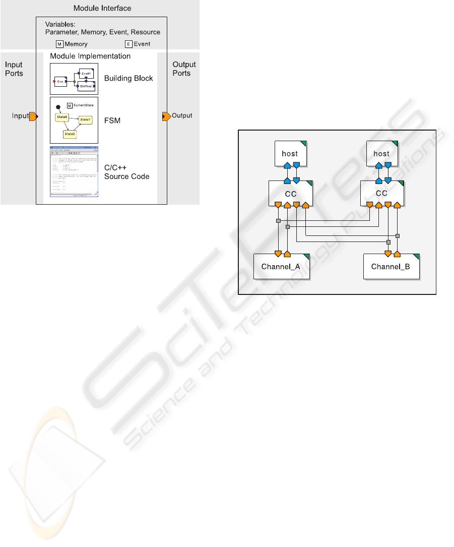
Figure 1: Model structure of a basic communication system.
The tool MLDesigner by MLDesign Technologies,
Inc. is dedicated to improve the design process from
early concepts to implementation. It is a tool offer-
ing mission and system level design, including oper-
ational, architectural and functional level, and evalu-
ation facilities. Build upon the well known Ptolemy
project of UC Berkeley (The Ptolemy Project, 2007)
it offers the same modeling techniques, but extends
them with new models and a better graphical repre-
sentation. Like Ptolemy, MLDesigner provides differ-
ent models of computation as so called domains. It of-
fers a discrete event domain (DE) and finite state ma-
chines (FSM), synchronous data flow domain (SDF)
as well as a continous time/discrete event domain
(CTDE) for numerically solving models given as dif-
ferential equations. The models created in MLDe-
signer are structured similar to those of Ptolemy. The
top level of the modeling hierarchy is called system.
A system includes all other used blocks and has no in-
terface to other blocks outside. Examples for building
blocks are shown in Figure 1. Those can be primi-
tives like FSM or C/C++ source code as elementary
blocks in the hierarchy. Other levels in the hierar-
chy are formed of modules, intern containing modules
or primitives. All building blocks possess different
types of variables. Parameters cannot be altered dur-
ing simulation meanwhile memories depicted by an
”M” in a box shown in Figure 1 are changeable. Vari-
ables can either be local or linked to a similar element
in the nexthigher hierarchy level. Building blocks can
communicate with their environment by using these
linked variables or through ports shown as arrows on
the bounding box of a building block. By the use
of wormholes the communication between building
blocks of different domains is supported. This very
flexible and powerful modeling paradigm offering a
top down design makes MLDesigner the best suited
tool for our modeling strategy.
5 FLEXRAY LIBRARY
5.1 Basic Model Structure
Figure 2: Model structure of a basic communication system.
Each communication system shown in Figure 2 is a
composition of three different elements: host, com-
munication controller (CC) and channel. A combina-
tion of a host and a CC is called node. The host con-
tains the application and is responsible for the config-
uration of the CC, initiation of the sending operation
and processing of the received data. At this point the
division into parts is visible, the host describes the
functionality and the CC describes the type of com-
munication. Nodes are grouped to communication
clusters by connecting them to a channel. Each clus-
ter consists of two channels, channel A and channel
B. The CC itself implements the communication pro-
tocol, e.g. the frame transmission and the frame re-
ception, and contains memories, which represent the
controller state and configuration data.
Interaction between model elements is realized us-
ing different data structures as signals. For the signal-
ing between host and CC the communication is ser-
vice based. Referring to this the data structure con-
tains a service identifier, a sub service identifier and
additional data required by the selected service. The
definition of these services is based on the FlexRay
specification. Dependent on the model type, abstract
MODEL BASED DESIGN OF NETWORKED EMBEDDED SYSTEMS - A Modeling Approach using FlexRay as an
Example
255

or detailed, the data exchangebetween differentnodes
via the channels is frame based or on bit level. To al-
low an easy exchange of the two models, abstract and
detailed model provide the same interface to the host.
This so called controller host interface (CHI) is part
of the CC. In the FlexRay specification the interface
functions are only roughly described, therefore this
basic description has to be filled to realize a precise
model.
In the following the models are described in more
detail. First there will be a short description of the
CHI, which is an important part of the abstract and the
detailed model, because it provides the same interface
towards an upper layer. Afterwards the abstract and
the detailed CC models will be explained.
5.2 Model Elements
5.2.1 Controller Host Interface
The CHI is responsible for the data and control flow
between CC and host. Beside the function as inter-
face, the CHI administrates the transmission and re-
ception buffer, manages the reception filter and pro-
vides access to configuration and status data. Both
reception and transmission buffer are CHI local mem-
ories, the same applies for the reception filter. The re-
ceive and transmission buffers are implemented with
unrestricted capacity. With regards to the primary
aims of the library it is not necessary to take limited
buffers into account. Each buffer is realized as a vec-
tor of data elements containing the relevant informa-
tion, example given frame identifier, channel, payload
length and payload data.
The CHI has two different interfaces, one to the
host by using the mentioned service based data struc-
ture and a second interface towards the CC protocol
functions. This second data structure can be inter-
preted as purely signal based. It is derived from the
protocol’s internal communication and contains a sig-
nal identifier and a field for additional data. A host
has write access to the transmission buffer and read
access to the reception buffer by using CHI services.
On the other side the protocol can use signals to write
received data into the reception buffer and to retrieve
data to send from the transmission buffer.
Each CC contains its own configuration, these
communication parameters are realized as memories,
too. Write access to the memories is only possible by
using the CHI and the provided services. Each host
is responsible for the correct configuration of its own
CC. So for configuration aspects it is not necessary
to parameterize the CHI module. To support the cre-
ation of a host an additional library is provided allow-
ing initialization, configuration, message sending and
reception.
5.2.2 Abstract CC Model
The design of a model starts with the question: What
is the operational aim of the model? Creating a de-
tailed model the answer is easy, the model has to be
built as accurately as possible. To achieve this the
specification is used as blueprint. As mentioned be-
fore the abstract model should allow a system anal-
ysis or development of systems on a higher level,
e.g. to support decisions in an early stage of de-
velopment. The abstract model of the FlexRay CC
uses some simplifications concerning the clock syn-
chronization mechanism, the temporal behavior and
the frame based data transmission. An external cen-
tral time master called Global Clock (GC) is responsi-
ble for synchronization and the timing of the FlexRay
communication.
The GC generates the cluster wide valid time,
which is represented by the so called macroticks
(MT). Important protocol values like the slot counter
for both FlexRay channels and the cycle counter are
derived from the MT. Each controller needs infor-
mation about important time events. In a FlexRay
cluster these are the slot starts. The GC announce a
change of the slot counter to all controllers. A con-
troller retrieves the actual counter values and checks,
if valid transmission data is available. In addition to
the medium access control the protocol model is also
responsible for data transmission and reception.
The description of the model can be divided into
two parts, one is the interface and the other is the
functionality and structure. Basic information about
the interfaces are already given, on one side of the
controller it is the well known CHI and on the other
side the controller communicates with the channel via
a data structure. This channel data structure contains
all relevantdata: frame identifier, payload data length,
cycle count, payload data and also some data for ad-
ministrative tasks, e.g. an error indicator. The ab-
stract model consists of the following modules: CHI,
UpdateStatus, SendtoChannel and ProcessRecData.
As shown in Figure 3 the controller has two mod-
ules SendtoChannel and two modules ProcessRec-
Data, one connected to channel A and one connected
to channel B. Each module itself has a complex in-
ternal structure consisting of further blocks based on
modules, MLDesigner primitives and newly devel-
oped custom primitives. The internal structure of the
modules will not be discussed in detail.
The module UpdateStatus receives events gener-
ated by the GC, updates the local time and triggers the
module SendtoChannel when a new slot starts. This
ICINCO 2008 - International Conference on Informatics in Control, Automation and Robotics
256

Figure 3: Internal structure of the abstract CC model.
module is responsible for the medium access control.
A data request signal is send to the CHI. Dependent
on the reply signal a data frame is created and send
to the channel. This data frame is forwarded by the
channel to all connected controllers and received by
the module ProcessRecData. After frame reception
and conversion the received data is forwarded to the
CHI containing the reception buffer.
To associate the simulation with the reality there
is a coherence between real time and simulation time.
An integer time step in the simulation is equivalent to
a second. This assumption is compatible to the de-
tailed model.
Preliminary performance tests have shown a real-
time to simulation time ratio of 1:200 in case of the
abstract model. Some small changes improved the ra-
tio to 1:20. It can be assumed that further improve-
ments are possible, example given by using optimized
data representation.
5.2.3 Detailed CC Model
The detailed model should allow an exact analysis
of the protocol and a system. The main benefit is,
that the internal behavior and the internal protocol
mechanisms can be visualized. As a result of the
detailed implementation of the clock synchronization
and the time generation mechanisms there are ad-
ditional functionalities feasible, like the simulation
based optimization of configuration parameters.
The model is called detailed, but there is also a
level of abstraction by comparison to a real system.
Beside the memory management the abstraction con-
cerns the communication. In real systems the data is
transmitted using analogous signals, in context of the
detailed model the communication is bit based. Each
controller transmits and receives a bit string and in-
terprets the data. An advantage of the modeling tool
MLDesigner is, that the model can be easily enhanced
using the CTDE domain, if a more detailed model
processing an analogous signal waveform is needed.
As mentioned above the FlexRay specification is
used as a kind of blueprint for the detailed model. The
specification itself is divided in different parts: the
protocol (FlexRay Consortium, 2005b) and the elec-
trical physical layer (FlexRay Consortium, 2005a)
specification. Due to the bit based communication the
focus lies on the protocol specification. The proto-
col is specified in a semi-formal way using text and
SDL
4
(ITU-T, 2002) to describe the functionalities.
The SDL semantic has been implemented in a suit-
able way by using MLDesigner elements. The FSM
domain in connection with DE modules allows the
realization of the protocol analog to the SDL speci-
fication. In the FlexRay specification is some space
left for interpretation. This concerns the realization
and use of the CHI, the controller configuration and
the memory management and the signaling and com-
munication of the SDL processes. First to mention
is, that all SDL processes are realized as FSMs. For
the intercommunication of the FSMs the MLDesigner
signaling concept is used in the following way. Ana-
log to the aforementioned signal mechanisms a data
structure is used. Different kinds of signals are used
in the specification: pure signals, signals with data
and function calls concerning the CHI. All of these
are implemented with one data structure containing
a signal name as identifier and a field to place ad-
ditional data. The internal communication is real-
ized by using this data structure. For the communi-
cation to other elements the detailed model provides
almost identical interfaces in comparison to the ab-
stract model. To the host the already known CHI
interface is used. An important part is the config-
uration of the controller. According to the abstract
model the configuration is initiated by the host and
the design is supported with an additional library. In-
teraction with the channel element is performed with
0 and 1 as bit values. The CC model as shown in
Figure 4 consists of a CHI module and different mod-
ules which are equivalent to the SDL processes de-
fined in the FlexRay specification. The modules CSP
(Clock Synchonization Processing), MTG (Macrotick
Generation) and POC (Protocol Operation Control)
exist only once, whereas the modules CODEC (Cod-
ing/Decoding Processes), CSS (Clock Synchroniza-
tion Startup), FSP (Frame and Symbol Processing)
and MAC (Medium Access Control) exist twice, one
per channel. Each process is implemented as a finite
state machine.
4
Specification and Description Language
MODEL BASED DESIGN OF NETWORKED EMBEDDED SYSTEMS - A Modeling Approach using FlexRay as an
Example
257
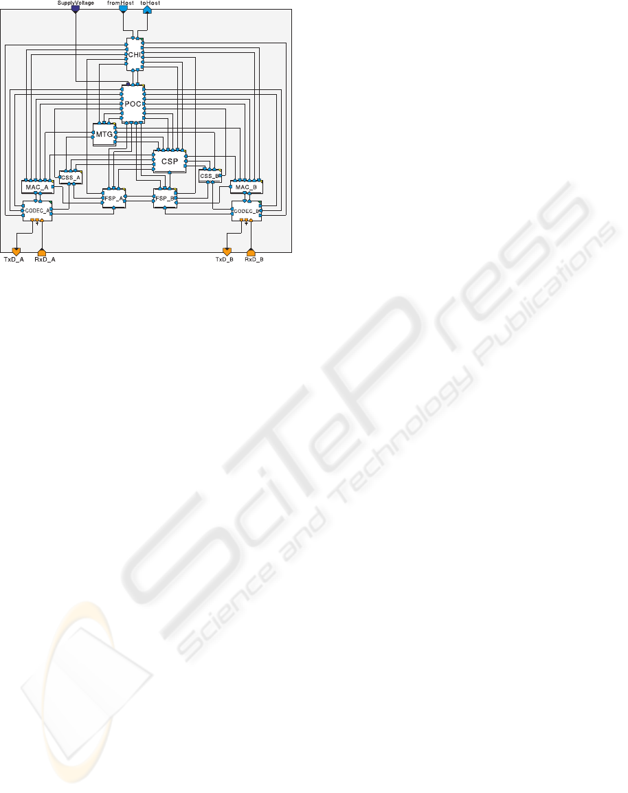
Figure 4: Internal structure of the detailed CC model.
5.2.4 Channel
There are two different types of channels, one for an
abstract CC and one for a detailed CC. Both have
functions to inject faults, forward and delay data.
A delay for frames is necessary to model a cor-
rect timing behavior, since the frame data structure is
completely transmitted at the start of a slot. Without a
delay the frame would be also received at the start of a
slot. Insertion of a delay, which is based on the trans-
mission rate and the data length, establishes a correct
timing.
Including errors and faults in a model is an impor-
tant facet when analyzing a system. A great advantage
of a model is the possibility to stress a system with an
arbitrary fault. There is no need for complex fault
injection or fault generation by using real scenarios
with expensive hardware. The design of a fault model
is a relevant part of the whole model library. Up
to now there exist some basic mechanisms to inject
faults, which will be improved in future. One fault
injection mechanism is a node failure - a node loses
bus synchronization and has to reconnect to the bus.
Another important failure injection mechanism is the
sending of erroneous data frames. The invalidation of
an abstract data frame is split into two parts. A frame
can be signed as invalid by using the error indicator.
The selection, if a frame is faulty, is also based on
a probability distribution and can be seen as the first
part of the fault model. A second part is the selection
of the error cause, this is probability controlled, too.
The fault model, which is part of the detailed chan-
nel, allows a more extensive and sophisticated analy-
sis. Not a whole frame can be marked as invalid, now
one single bit can flip with the effect, that the error
check mechanisms can be proofed as well. With an
additional marking of flipped bits it can be tested, if a
transmission error was detected or remaind undiscov-
ered. Additional to these data frame errors it is pos-
sible to insert synchronization faults. In many cases
fault models perform an important role, not only in
the analysis of protocol performance, but also in the
analysis of higher-level behavior. This could be the
comparison of different fault handling strategies.
5.3 Validation
An important task in building models has not been
mentioned yet, the validation of the model. Is the be-
havior of the developed model equivalent to the spec-
ified system? A short discussion of the validation of
both models is given. The validation of the models is
delicate because of the different monitoring feasibil-
ity. A real system allows only limited access to the
internal behavior of the controller. As a result an ex-
act comparison was not possible. The model allows
a detailed monitoring, fault injection and analysis of
every internal signal, none of which is provided by a
real controller. In case of the not visible aspects the
validation is based on the assumed behavior described
in the FlexRay specification. The abstract model was
tested by comparing it with the send behavior of a real
system. As reference a system of two communicating
FlexRay nodes is used. The communication and the
timing behavior in normal and fault scenarios is com-
pared with th results of an equivalent model. The re-
sults show, that the modeled system behaves like the
real system. To validate the detailed model and the
CHI another way is chosen. Here the model is com-
pared to the specification and the behavior is shown
by simulation of test scenarios. The complexity of
the examples varies from small module tests to whole
system tests. The detailed model was tested against
the real two-node system, too. Comparison of the ob-
servable behavior of model and real system showed
the same results.
6 CONCLUSIONS
In this paper a modeling strategy was described,
which enables the design of models dealing with
automotive communication systems like CAN and
FlexRay. The resulting model provides concepts to
monitor both, the behavior of networked systems and
the internal behavior of the communication. This will
allow easy fault injection as well as a schedulability
analysis dependent on the selected bus system. The
presented library developed for MLDesigner uses the
discrete event domain in combination with FSMs and
ICINCO 2008 - International Conference on Informatics in Control, Automation and Robotics
258

demonstrates the approach with FlexRay as an exam-
ple. Modularized components are part of the library.
These so called building blocks allow an easy con-
struction of a wide range of systems. The library in-
cludes modules implementing the FlexRay communi-
cation controller and a basic host system, which pro-
vides elementary functionalities needed in the design
of hosts and applications. The components can be
used to construct models for networked systems and
subsystems or to develop models for gateways. The
use of different communication protocols and gate-
ways enable the simulation and the analysis of com-
plex systems. Furthermore the concept is designed to
assist in migrating parts of networked systems from
CAN bus usage to FlexRay. The developed models
with different degrees of abstraction support the de-
velopment in early stages and enable the evaluation
and verification of system properties prior to hard-
ware design.
7 FUTURE WORK
The next step in applying this approach will be the
design of monitoring modules to support the analysis
of the FlexRay protocol itself during a simulation run
and to provide all necessary information for debug-
ging systems or generating results, e.g. for schedula-
bility.
The completion of a CAN bus model is necessary.
This will allow the seamless integration of CAN mod-
els into systems designed for FlexRay and vice versa,
also simulating the migration of network parts from
CAN to FlexRay will be possible.
Future work will also deal with the automated
generation of models. Therefor the FIBEX (ASAM,
2007) standard will be utilized. It will allow to de-
scribe all important parameters of FlexRay and CAN
systems to generate the network structure. With an
extension of the FIBEX XML files might be possible
to generate a complete system model based upon a
FIBEX description using additional information. This
process will be done by an XSLT transformation of
the FIBEX file into an MLDesigner model also spec-
ified using XML files.
After the completion of the communication part
of a system the functional part has to be added. Dif-
ferent modules implementing e.g. a gateway func-
tionality will be designed. A future publication will
deal with different mapping strategies usable within
these gateways based on the concept and the mod-
els described in this paper. Modules for different
host systems and operating systems will be added to
support OSEK (OSEK/VDX, 2005) and OSEKtime
(OSEK/VDX, 2001) compatible systems.
Finally we will create a system level model for
an existing real world scenario in automotive appli-
cations to demonstrate our new approach in modeling
systems.
ACKNOWLEDGEMENTS
This work was funded by the ”Th¨uringer Auf-
baubank”
5
under joint projekt number ”2006 VF
0014”.
REFERENCES
ASAM (2007). FIBEX - Field Bus Exchange Format Ver-
sion 2.0.1.
Carsten B¨oke (2006). Regler real testen. Design/Elektronik
07/2006.
FlexRay Consortium (2005a). FlexRay Communications
Systems - Electrical Physical Layer Specification Ver-
sion 2.1.
FlexRay Consortium (2005b). FlexRay Communications
Systems - Protocol Specification Version 2.1.
FlexRay Consortium (2007).
http://www.flexray.com
.
ITU-T (2002). ITU-T Recomondation Z.100 (08/02): Spec-
ification and Description Language (SDL).
MLDesign Technologies Inc. (2007). MLDesigner Docu-
mentation, Version 2.7.
http://www.mldesigner.
com/
.
OSEK/VDX (2001). OSEK/VDX time triggered operating
system Version 1.0.
OSEK/VDX (2005). OSEK/VDX Operating System Version
2.2.3.
Richter, K. (2007). Scheduling analysis for flexray. In KFZ-
Entwicklerforum und FlexRay Solution Day 2007.
WEKA.
Robert Bosch GmbH (1991). CAN Specification Version
2.0.
Salzwedel, H. (2004). Design technology development to-
wards mission level design. In 49. Internationales
Wissenschaftliches Kolloquium IWK’2004.
The MathWorks (2007). Matlab 7 - Desktop Tools and De-
velopment Environment.
http://www.mathworks.
com/
.
The Ptolemy Project (2007).
http://ptolemy.eecs.
berkeley.edu/
.
5
http://www.aufbaubank.de
MODEL BASED DESIGN OF NETWORKED EMBEDDED SYSTEMS - A Modeling Approach using FlexRay as an
Example
259
