
USING STEREO VISION AND TACTILE SENSOR FEATURES
For Grasp Planning Control
Madjid Boudaba
1
, Nicolas Gorges
2
, Heinz Woern
2
and Alicia Casals
3
1
TES Electonic Solution GmbH, Zettachring 8, 70567 Stuttgart, Germany
2
Institute of Process Control and Robotics, University of Karlsruhe
Engle-Bunte-Ring 8-Gebaeude 40.28, 76131 Karlsruhe, Germany
3
GRINS: Research Group on Intelligent Robots and Systems
Technical University of Catalonia, Pau Gargallo 5, 08028 Barcelona, Spain
Keywords:
Stereo vision, Tactile sensors, Grasp planning, Features matching.
Abstract:
Planning the grasp positions either from vision or tactile sensors one can expect various uncertainties. This
paper describes a scheme that match visual stereo and tactile data based on stereo vision and tactile sensors.
For grasp planning, initially, the grasping positions are generated from stereo features, then the feedback of
tactile features is used to match these positions. The result of the matching algorithm is used to control the
grasping positions. The grasping process proposed is experimented with an anthropomorphic robotic system.
1 INTRODUCTION
In recent years, considerable research in robotic
grasping systems has been published. The pro-
posed system works by using the principle of
sensing-planning-action. To place our approach in
perspective, we review existing methods for sensor
based planning for grasping. The existing literature
can be broadly classified into three categories; vision
based, tactile based and both vision-tactile based. For
all categories, the extracted image features are key
factors, they can range from geometric primitives
such as edges, lines, vertices and circles to optical
flow estimates. The first category uses visual image
features to estimate the grasping points and from
them define the robot’s motion with respect to the
object position and orientation before performing a
grasp (Yoshimi and Allen, 1994), (Maekawa et al.,
1995), (Smith and Papanikolopoulos, 1996), (Sanz
et al., 1998), (Kragic et al., 2001), and (Morales
et al., 2002). The second category uses tactile image
features to estimate the characteristics of the area in
contact with the object (Berger and Khosla, 1991),
(Chen et al., 1995), (Perrin et al., 2000), and (Lee
and Nicholls, 2000). The last category uses data
fusion from both vision and tactile sensors in order
to control grasping tasks efficiently (Namiki and
Ishikawa, 1999), and (Allen et al., 1999).
This paper is an extension of our previous work
(Boudaba and Casals, 2006) and (Boudaba and
Casals, 2007) on grasp planning using visual features.
In this work, we demonstrate the utility of matching
both visual and tactile image features in the context
of grasping, or fingers position controlling. In our
approach, we avoid using any object model, and in-
stead, we work directly from image features to plan
the grasping points. In order to avoid finger position-
ing errors, matching, by back projecting these tactile
features into visual features is required to compute the
similarity transformation that relates the grasping re-
gion with the sensitive touching area. To achieve a
high level of grasping position matching efficiency,
two matching schemes are considered in this paper.
The first establishes grasp points correspondences be-
tween the left and right images of the stereo head. In
this scheme, only the grasp positions are back pro-
jected into one side of the stereo image. A second
scheme is a region matching where the whole sensi-
tive touching area with the object is used in the back
projection into the visual image. All the points be-
longing to the sensitive area of a tactile sensor are
back-projected into the grasp region of visual fea-
tures. The processing in each match is completely
independent and can be performed at its own rate.
Our approach based on features matching can play the
214
Boudaba M., Gorges N., Woern H. and Casals A. (2008).
USING STEREO VISION AND TACTILE SENSOR FEATURES - For Grasp Planning Control.
In Proceedings of the Fifth International Conference on Informatics in Control, Automation and Robotics - RA, pages 214-221
DOI: 10.5220/0001492902140221
Copyright
c
SciTePress
critical role of forcing the fingertips to move towards
the desired positions before the grasping is executed.
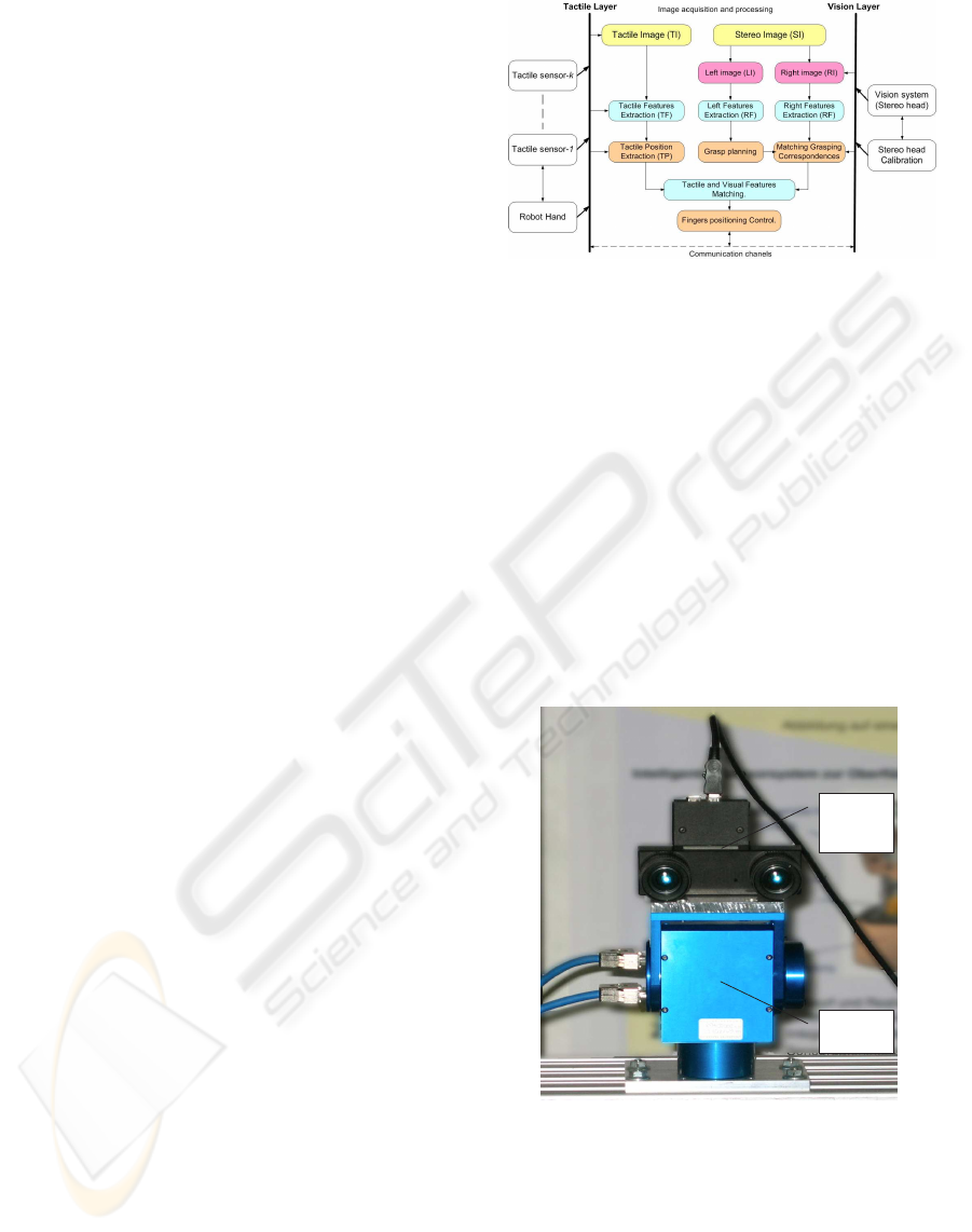
2 GRASPING SYSTEM
DESCRIPTION
In robotic grasping tasks, when data from several
sensors are available simultaneously, it is generally
necessary to precisely analyze all of them along the
entire grasping process (see Figure 1). The object
being extracted from a video sequence requires
encoding its contour individually in a layered manner
and provide at the receiver’s side some enhanced
visual information. In the same way, from the data
being extracted from a tactile sensor, the tactile layer
processes and provides the tactile information at
its receiver’s side. The architecture of the whole
grasping system is organized into several modules,
which are embedded in a distributed MCA2 (Mod-
ular Controller Architecture Version 2) software
framework (Scholl et al., 2001). There are mainly
three modules involved in this development; the
stereo vision, tactile sensors, and grasp planning.
In MCA2, every module is structured in a data
vector that allows the module to receive and send
the data from/to other modules, or to take any part
of an output data and permute and copy it to other
modules. In order to control its current functionality,
every module has fully or partially access to the input
data of the other modules depending on the tasks
involved. For instance, the grasp planning module
has full access to the input data of the sensory system
and has partially access to the robot hand. Because
the architecture of the system has a global planning
to access to all the data available to the system, the
grasp planning module can locally plan the grasping
positions without having a global view of the robot’s
environment. For instance, the robot hand needs
some information supplied by the global planning
module such as grasp configurations for the object to
be grasped.
2.1 Visual Layer: Feature Extraction
We consider visual features extraction in the context
of a stereo head (see Figure 2). First, however,
we recall the epipolar geometry technique which is
motivated by considering the search of corresponding
points in the stereo image pair. Since we are dealing
with a stereo head, we need to extract features well
suited for determining the grasp points on the first
image either from the left or right side of a stereo
Figure 1: Grasping system description.
pair and then computing their correspondences in
the second image. Given the estimated object pose,
placed on the table, the full observability of the
object is then projected into the left and right image
planes. The visual layer takes these images and
calibration data as input (see Figure 1) and provides
as output a set of visual features. Segmentation is
used to separate the object from the background
and other objects in the environment by determining
the coordinates of a closed rectangular bounding
box. After segmenting the region corresponding to
the object, features belonging to the object contour
are extracted. A function is then constructed for
parameters regrouping object features together.
Stereo
camera
system
Pan-tilt
unit
Figure 2: Stereo camera system and a Pan-tilt unit.
We denote by V a function regrouping visual pa-
rameters that is defined by
V = {glist, g
param
, com} (1)
where glist, g
param
and com are the visual features.
During image processing, V is maintained as a dou-
bly linked list of grasping region and intervening their
USING STEREO VISION AND TACTILE SENSOR FEATURES - For Grasp Planning Control
215
parameters as g
1
g
param
1
, ··· , g
m
g
param
m
. A grasping
region g
i
is defined by its ending points g
ui
and g
vi+1
,
and its orientation φ with respect to the object’s center
of mass com. The resulting parameters of V fully de-
scribe the two-dimensional location of features with
respect to the image plane The visual features ob-
tained can be used as input data for both, grasp plan-
ning and grasp position matching. For more details
about this topic, we refer the reader to our previous
work (Boudaba and Casals, 2007).
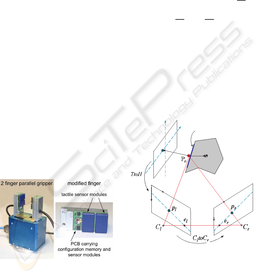
2.2 Tactile Layer: Feature Extraction
Unlike vision which provides global features of the
object, tactile sensor provides local features when
the fingertip is in contact with the object. The tactile
layer shown in Figure 1 takes as input the data ex-
tracted from a set of tactile sensor (or so called Group
Of Tactile sensor (GOT)) and the configuration of
the robot hand and provides as output a set of tactile
features. To simplify the problem, tactile features
are treated as visual features using the basic results
from different approaches. For the purpose of sensor
features matching, extracting edge features are of
interest and will be discussed in section 4. Figure
3 illustrates the PCB tactile sensor module with its
memory and data control units. The sensor module
(from Weiss Robotics, (K.Weiss and Woern, 2005))
consists of a sensitive area organized in matrix of 4x7
sensor cells with a spacial resolution of 3.8 mm. By
using four modules, (two in each gripper finger), the
parallel gripper shown in Figure 3 is equipped with a
total number of 112 sensor cells.
Figure 3: Gripper equipped with tactile sensor modules.
The data of the tactile sensor matrix corresponds
to a two-dimensional planar image. We analyze this
image using moments up to the 2
nd
order (Hu, 1962).
The two-dimensional (p+ q)
th
order moment m
p,q
of
an image is defined as the following double sum over
all image pixels (x, y) and their values f(x, y):
m
pq
=
∑
x
∑
y
f(x, y)x
p
y
p
p, q ≥ 0 . (2)
The moment m
0,0
constitutes the resulting force ex-
erted on the sensor. The center of gravity cog =
(x
c
, y
c
)
T
of this force can be computed as follows:
x
c
=
m
10
m
00
, y
c
=
m
01
m
00
. (3)
The center of gravity of each tactile sensor matrix
determines a contact point of the gripper.
3 GRASP POSITION MATCHING
The Grasping system can be explained in more
detail through a set of tasks. In order to complete
the grasp matching process, it is necessary to find
the relationship between their Cartesian coordinate
frames (see Figure 4).
v
t
T
a
c
t
i
l
e
P
l
a
n
e
I
m
a
g
e
P
l
a
n
e
r
i
g
h
t
t
d
u
t
l
u
l
v
r
u
r
v
o
d
Grasping region
OCS
Object
I
m
a
g
e
P
l
a
n
e
l
e
f
t
t
p
Figure 4: Sensor frames relationship for grasping.
We define these frames as follows:
• HCS. Head Coordinate System has a stand
alone configuration of stereo head. The fixation
of the head is assured by controlling the pan-tilt
angle. The offset to the object coordinate system
(OCS) is constant.
ICINCO 2008 - International Conference on Informatics in Control, Automation and Robotics
216

• GCS. Gripper Coordinate System (also known
as the end effector frame) is determinated by con-
trolling the angular configuration of the robot arm.
The robot arm moves over itself and the measure-
ments given by all joints enable the system to de-
termine the Tool-Center-Point (TCP) relative to
the robot coordinate system.
• OCS. Object Coordinate System is fixed on the
table and does not change its position and orienta-
tion during calibration. Once the object pose rela-
tive to the stereo head (HCS) is determinated, the
GCS relative to the object pose is determinated by
using robot hand - stereo head calibration.
• TCS. Tactile Coordinate System. The location
of TCS is terminated by controlling the GCS con-
figuration.
• WCS. World Coordinate System. The location
of the object position and orientation OCS, HCS
and the robot base station are determinated rela-
tive to the WCS.
In the remaining of this work, the kinematics of
the robot arm and robot hand are ignored. So far,
for grasping using features matching, we have es-
tablished two mapping relationships between feature
frames. The first mapping implies finding the grasp
points correspondence between left and right image
of the stereo head (C
l
toC
r
). The second mapping
implies matching the two apparent features into the
tactile and stereo frames (TtoH).
3.1 Stereo Images Matching: C
l
toC
r
We adopt some notations similar, but not identical
to the work of (Hartley and Zisserman, 2000) on
multiple view geometry (see Figure 4). Considering
a point P
o
in contact with the object, its distance to
the center of mass, d
o
is measured and its projection
into the stereo head and tactile frames is given by
(p
l
, p
r
) and p
t
, respectively. The subscripts, o, c, l,
r, and t are referred to object, contact point, left and
right frames, and tactile frame, respectively.
Let p
r
= (u
r
, v
r
, 1)
T
and p
l
= (u
l
, v
l
, 1)
T
denote
the projection of P
o
on the right and left images, re-
spectively. The epipolar plane defined by the three
points P
o
, C
l
and C
r
intersects the two image planes
in two epipolar lines ep
r
and ep
l
. The line connect-
ing the two centers of projection [C
l
,C
r
] intersects the
image planes at the conjugate points e
r
and e
l
which
are called epipoles. Using the projective coordinates,
the epipolar constraints can be written:
p
T
l
Fp
r
= 0 (4)
where F is the so-called fundamental matrix
which consists of a 3x3 unknown entries and can be
expressed as follows:
F =
f
11
f
12
f
13
f
21
f
22
f
23
f
31
f
32
f
33
(5)
In the calibrated environment, the 9 unknown entries
of F can be captured in an algebraic representation as
defined by
F = C
−T
r
EC
−1
l
(6)
where the fundamental matrix F encapsulates both
the intrinsic and the extrinsic parameters of the stereo
head, while the essential matrix E = [T]
×
R which
compactly encodes the extrinsic parameters of the
stereo head can be composed of the baseline vector
t = [C
r
−Cl] = (t
x
, 0, t
z
)
T
and the angular rotation β
about the y-axis that renders the left image parallel to
the right one, then we have:
E =
0 −t
z
0
t
z
0 −t
x
0 t
x
0
cos(β) 0 −sin(β)
0 1 0
sin(β) 0 cos(β)
(7)
C
l
and C
r
are the intrinsic parameter matrices of
the left and right cameras defined by
C
l
=
f
u
l
0 C
ul
0 f
v
l
C
vl
0 0 1
, C
r
=
f
u
r
0 C
ur
0 f
v
r
C
vr
0 0 1
(8)
where u
0l
and v
0l
(resp. u
0r
and v
0r
) are the coor-
dinates of the principle point (in pixels) of the left
(resp. right) camera. ( f
x
, f
y
) are the focal length in x
and y direction.
For more details about camera calibration and re-
lated topics, we refer to the work of (Faugeras and
Toscani, 1986) and (Tsai and Lenz, 1989).
3.2 Tactile and Stereo Matching: TtoH
By dealing with the contact constraint, the minimum
distance between a fingertip (tactile) and the object
can be expressed by a parameter d
t
. So keeping a fin-
gertip in touch with the object, the condition d
t
= 0
must be maintained, and tactile features are extracted
and measured into the tactile frames. Matching these
tactile features with visual features implies the com-
putation of a similarity transformation relating the
USING STEREO VISION AND TACTILE SENSOR FEATURES - For Grasp Planning Control
217

grasping region to actual sensitive touching area. Tac-
tile and visual features are then related by the follow-
ing transformation
s
i
= TtoHv
i
(9)
where s
i
and v
i
are points on the tactile and visual
image features, respectively. TtoH is the similarity
transformation given by
TtoH =
scosα −sinα t
x
sinα scosα t
y
0 0 1
(10)
where s , α, and [t
x
, t
y
, 1] are scaling, rotation angle
and translation vector of the tactile image with
respect to the visual image, respectively.
In the calibration cases, the parameters of (10) can
be computed directly using homogeneoustransforma-
tion matrices between frames as shown in Figure 4.
4 IMPLEMENTATION
The implementation of our algorithm for grasping
position matching using stereo vision and tactile
sensor can be divided into two parts. First is related
to the grasp planning using stereo vision. The
second part of this implementation is related features
matching between stereo vision and tactile sensor.
4.1 Grasp Planning using a Stereo Head
As stated before, the first implementation con-
sists of computing the grasp points correspon-
dence in the stereo vision. More formally, let
G =
G
v
1
, G
v
2
, · ·· , G
v
k
be a set of valid grasps and
G
l
v
i
= (g
l
u
i
, g
l
v
i
, 1)
T
be its ith− determinated grasp
point on the left image, next step is to compute its cor-
respondence on the right image, G
r
v
i
= (g
r
u
i
, g
r
v
i
, 1)
T
.
To do this, we first need to establish a mapping
relationship between a line and point by exploiting
the epipolar constraint defined by (4).
Let
L
r
i
= FG
l
v
i
, L
l
i
= F
T
G
r
v
i
(11)
be the mapping equations where F
T
is the transpose
of F and i := 1, 2, ..., k is the number of grasping
points. G
l
v
i
(resp. G
r
v
i
) is the determinated grasp point
on the left (resp. right) image and L
r
i
(resp. L
l
i
) is
its corresponding epipolar line on the right (resp.
left) image. By exploiting the epipolar constraint (4),
the grasping points are constrained to lie along the
epipolar lines L
r
i
and L
l
i
, respectively.
If both grasping points satisfy the relation
G
l
v
i
FG
r
v
i
= 0 then the lines defined by these points are
coplanar. This is a necessary condition for the grasp
points to correspond.
Given the parameters of a line and a grasp point
in one image, the maximum deviation of a point from
the line can be computed as follows:
d
2
l
i
= norm(L
l
i
, G
l
v
i
), d
2
r
i
= norm(L
r
i
, G
r
v
i
) (12)
where d
2
l
i
(resp. d
2
r
i
) is the maximum deviation of a
grasp point on the left (resp. right) image.
We can estimate a cost function with respect to a
parameter t as follows:
C(t) = d
2
l
i
+ d
2
r
i
(13)
The minimum threshold (t
min
) corresponds to the t
i
where the cost function is minimum.
4.2 Features Matching
The second implementation consists of computing
the similarity between the stereo and the tactile
images features. To compare image features, the
Hausdorff metric based on static features matching is
used (Huttenlocher et al., 1993).
Given two feature sets: S =
s
1
, s
2
, ..., s
q
and
V =
v
1
, v
2
, ..., v
q
, the Hausdorff distance from the
point set S to point set V is defined as
h(S, V) = maxmin
s∈Sv∈V
s
i
− v
j
(14)
where
s
i
− v
j
corresponds to the sum of the pixel
difference and indices i and j correspond to the size
of a searching window.
The matching process is evaluated according to
the output of the function (14). The matching that
results in the lowest cost is the one that matches the
closest grasp planning. Since we want to guide the
gripper toward the grasping points previously gener-
ated by the grasp planning, the solution consists of re-
ducing the cost function (or so called grasp error) by
ICINCO 2008 - International Conference on Informatics in Control, Automation and Robotics
218
Table 1: Parameters measure of grasping positions and cost function: obj1, obj2.
Threshold: t = 2 corresponds to the maximum deviation.
Object Left grasp (x
l
, y
l
) d
l
Right grasp (x
r
, y
r
) d
r
C
G
l
v
1
358.500 365.500 2.934 G
r
v
1
313.500 377.000 2.940 17.252
obj1 G
l
v
2
359.000 400.000 5.008 G
r
v
1
312.500 411.500 5.018 50.261
G
l
v
1
355.000 226.000 1.726 G
r
v
1
299.500 237.500 1.731 5.9768
obj2 G
l
v
2
363.000 314.500 0.922 G
r
v
1
309.000 323.500 0.926 1.7028
G
l
v
3
309.500 316.500 5.251 G
r
v
1
255.000 321.500 5.259 55.234
(a) obj1: Left image (b) obj1: Right image (c) obj2: Left image (d) obj2: Right image
(e) Left image features (f) Right image features (g) Left image features (h) Right image features
Figure 5: Result of two and three-fingered grasp planning algorithms using stereo images.
moving the tactile sensors toward these points. The
cost of a solution is expressed as the total sum of con-
tact displacements over the surface of the object from
an initial contact configuration. If the result of match-
ing is outside a givenmargin, then the grasp controller
should launch a new measurement via joint angle and
position sensors.
4.3 Matching Algorithm
• Input: images: im
1
, im
2
. features: V
1
, V
2
. Num-
ber of fingers: k. Fundamental matrix: F. Thresh-
old t. Size of window: 7x7 pixel.
• Output: Grasping points: (G
l
v
i
, G
r
v
i
), with i :=
1, ..., k. Matching: h(S, V)
Process:
1. Perform the features extraction tasks
• for i := 1 to 2 do
• extract features: V
i
:= im
i
.
2. Perform the grasp planning tasks
• select V
1
on which the grasp will be performed.
• Get valid grasps point G
v
from (1)
3. Perform the grasping point correspondences
• select V
2
on which the grasping correspon-
dences will be performed
• for i := 1 to k do
• Compute G
l
v
i
:= G
v
i
• Compute L
r
i
and G
r
v
i
using (11)
4. Perform the matching function
• for i, j := 1 to 7, 7 do
• Compute h(S, V) ≤ r and h(S, V) ≥ r
• Compute pixel difference h(S, V) from (14)
USING STEREO VISION AND TACTILE SENSOR FEATURES - For Grasp Planning Control
219
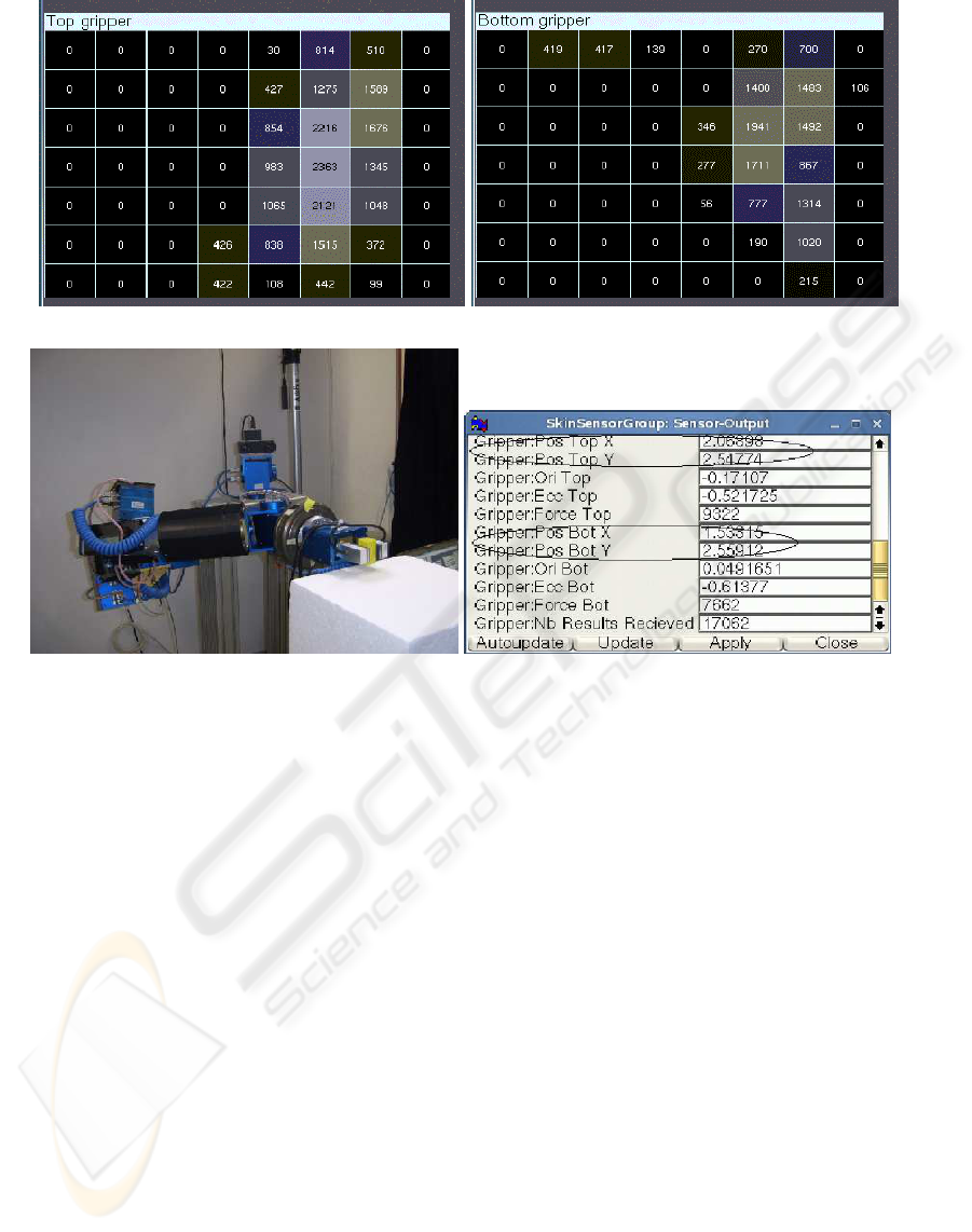
(a) Tactile sensor feedback: top gripper (b) Tactile sensor feedback: bottom gripper
(c) Gripper grasping an object (d) Fingers position
Figure 6: The Experiment setup. (a)-(b) Tactile sensor feedback giving the sensitive area in contact with the object. (c) Object
grasped with two fingers parallel gripper. (d) Tactile sensor output giving the top/bottom position of the gripper.
5. Perform the cost function
• Compute d
2
l
i
and d
2
r
i
using (12)
• Compute C(t) with (13)
6. End.
4.4 Experimental Results
The algorithm was implemented on our experimental
system, which consists of a 7 DOF manipulator arm,
a robot hand with two fingers, each one equipped with
a tactile sensor module mounted directly to the finger
tip, and a vision system (see Figure 6). This first pro-
totype of anthropomorphic robot system developed
by the German Research Foundation (see (Boudaba
et al., 2005)) is used as platform and demonstrator for
a coming generation of service robots. The grasping
configuration is based on a stand-alone stereo head
(MEGA-D from Videre Design) mounted on a pan-
tilt controller unit equipped with a pair of 4.8 mm
lenses and a fixed baseline of about 9cm. We have
experimented our approach with two different kind of
objects placed on a fixed table with a fixed position
and orientation (static object). Figure 5 illustrates the
results obtained from our matching algorithm using
stereo vision. The performance of our results (see Ta-
ble 1) is validated according to a cost function C de-
fined in the stereo images as the errors between grasp-
ing points. The cost that results in the lower value is
the one that matches the closest grasp planning. Fig-
ures 6(b)-(d) illustrate the feedback of tactile sensor
giving the top/bottom position of fingers with respect
to the tactile image plane in (b) while (c)-(d) showing
the top/bottom sensitive area in touch with the object.
5 CONCLUSIONS
The implementation of our algorithms for grasping
points matching using stereo vision and tactile sen-
sor have been detailed. Two schemes for grasping
points matching have been included in this work. In
the first scheme, stereo vision matching was used to
find the grasp points correspondence between left and
right images. It is shown that the quality of matching
ICINCO 2008 - International Conference on Informatics in Control, Automation and Robotics
220

depends strongly on the precise computation of the
intrinsic and extrinsic parameters of the stereo head
calibration. The performance of our results is evalu-
ated according to a cost function defined in the stereo
images as the errors between a pair of grasping points.
In the second scheme, the tactile sensor provides the
sensitive area of a fingertip in contact with an object
which was used with the grasp region to compute the
similarity between both features. Using these two
matching schemes, we were able to fuse the visual
grasp region with the tactile features and capabilities
of reducing or avoiding the grasp positioning errors
(or so called controlling the grasp planning) before
executing a grasps.
REFERENCES
Allen, P., Miller, A., Oh, P., and Leibowitz, B. (1999). Inte-
gration vision, force and tactile sensing for grasping.
Int. Journal of Intell. Mechatronics, 4(1):129–149.
Berger, A. D. and Khosla, P. K. (1991). Using tactile data
for real-time feedback. International Journal of of
Robotics Research (IJR’91), 2(10):88–102.
Boudaba, M. and Casals, A. (2006). Grasping of planar
obbjects using visual perception. In Proc. IEEE 6th
International Conference on Humanoid Robots (HU-
MANOIDS’06), pages 605–611, Genova, Italy.
Boudaba, M. and Casals, A. (2007). Grasp configuration
matching using tactile and visual information. In Proc.
IEEE 4th International Conference on Informatics in
Control, Automation and Robotics (ICINCO’07), vol-
ume Vol. II, pages 121–127, Angers, France.
Boudaba, M., Casals, A., Osswald, D., and Woern, H.
(2005). Vision-based grasping point determination
on objects grasping by multifingered hands. In Proc.
IEEE 6th International Conference on Field and Ser-
vice Robotics, pages 261–272, Australia.
Chen, N., Rink, R. E., and Zhang, H. (1995). Edge tracking
using tactile servo. In Proc. IEEE/RSJ International
Conference on Intelligent Robots and Systems, pages
84–99.
Faugeras, O. D. and Toscani, G. (1986). The calibration
problem for stereo. In In Proc. IEEE Conference on
Computer Vision and Pattern Recognition, CVPR’86,
pages 15–20, Miami Beach, FL, USA.
Hartley, R. and Zisserman, A. (2000). Multiple View Geom-
etry in Computer Vision. Cambridge University Press,
England, UK.
Hu, M.-K. (1962). Visual Pattern Recognition by Moment
Invariants. IEEE Transactions on Information Theory,
8(2):179–187.
Huttenlocher, D., Klanderman, D., and Rucklige, A. (1993).
Comparing images using the hausdorff distance. IEEE
Transaction on Pattern Analysis and Machine Intelli-
gence, 15(9):850–863.
Kragic, D., Miller, A., and Allen, P. (2001). Real-time
tracking meets online grasp planning. In Proc. IEEE
International Conference on Robotics and Automata-
tion (ICRA’2001), pages 2460–2465, Seoul, Korea.
K.Weiss and Woern, H. (2005). The working principle of re-
sistive tactile sensor cells. In Proceedings of the IEEE
Int. Conf. on Mechatronics and Automation, pages
471–476, Ontario, Canada.
Lee, M. H. and Nicholls, H. R. (2000). Tactile sensing for
mechatronics - a state of the art servey. Mechatronics,
9:1–31.
Maekawa, H., Tanie, K., and Komoriya, K. (1995). Tac-
tile sensor based manipulation of an unknown object
by a multifingered hand with rolling contact. In Proc.
IEEE International Conference on Robotics and Au-
tomatation, pages 743–750.
Morales, A., Sanz, P., and del Pobil, A. (2002). Heuris-
tic vision-based computation of three-finger grasps
on unknown planar objects. In Proceedings of the
IEEE/RST Int. Conf. on Intelligent Robots and Sys-
tems, pages 1693–1698, Lausanne, Switzerland.
Namiki, A. and Ishikawa, M. (1999). Optimal grasping us-
ing visual and tactile feedback. In Proceedings of the
IEEE/RST Int. Conf. on Intelligent Robots and Sys-
tems, pages 589–596.
Perrin, D., Smith, C., Masoud, O., and Papanikolopoulos,
N. (2000). Unknown object grasping using pressure
models. In Proceedings of the IEEE International
Conference on Multisensor Fusion and Integration for
Intelligent Systems, pages 575–582.
Sanz, P., del Pobil, A., Iesta, J., and Recatal, G. (1998).
Vision- guided grasping of unknown objects for ser-
vice robots. In ICRA’98, page 30183025, Leuven,
Belgium.
Scholl, K. U., Albiez, J., and Gassmann, B. (2001). MCA -
An Expandable Modular Controller Architecture. 3rd
Real-Time Linux Workshop.
Smith, C. and Papanikolopoulos (1996). Vision-guided
robotic grasping: Issues and experiments. In ICRA’96,
pages 3203–3208.
Tsai, R. Y. and Lenz, R. K. (1989). A new techniques for
fully autonomous and effecient 3d robot hand/eye cal-
ibration. IEEE Trans. on Robotics and Automation,
5(3):345–358.
Yoshimi, B. H. and Allen, P. K. (1994). Visual control of
grasping and manipulation tasks. In Proc. IEEE In-
ternational Conf. on Multisensor Fusion and Integra-
tion for Intelligent Systems, pages 575–582, Las Ve-
gas, USA.
USING STEREO VISION AND TACTILE SENSOR FEATURES - For Grasp Planning Control
221
