
HUNTER – HYBRID UNIFIED TRACKING ENVIRONMENT
Real-time Identification and Tracking System using RFID Technology
A. G. Foina and F. J. Ramirez Fernandez
Escola Politécnica - Universidade de São Paulo, São Paulo, SP, Brazil
Keywords: RFID, Middleware, Tracking, Real-time, Supervision, Wi-Fi, Wireless.
Abstract: This article presents a developed system that use RFID technology for trucks’ cargo real-time tracking.
RFID tags were settled at trucks’ dump-carts and readers were spread throughout warehouses entrances, at
the truck weighting scale and through unload platforms. The unload inspectors used robust PDA with
camera, along with Wi-Fi access points installed in warehouses, to confirm the truck information and take a
snapshot for future audits. A wireless broadband link was used to connect two weighting scale that are
distant from the unloading area. All technologies communicate with a web-based middleware that manages
all different devices. The system design is flexible enough to be used in very different applications like
product process control, automated manufactory lines control, supply chain applications and others.
1 INTRODUCTION
The unloading of bulk cargo is a great security
problem for companies that work with this product
modality, since the unloading process consists in
three tasks:
1. Full weight, which the truck is weighed with
full loaded dump-cart;
2. Unload, which the truck goes to a designated
site and unloads the product;
3. Empty weight, which the truck is once again
weighed unloaded.
The amount unloaded by the truck is the
difference between the second and first weight.
Thus, if a load theft occurs in the period between the
two weights, the company will not be able to know
if the theft had occurred or even how much was
stolen.
In some ports, the exporting companies' area is
open to access by anyone or any vehicle, and the
weight sites are approximately 2 kilometers far. This
scenario makes the cargo theft possible by the
following form: the truck is weighed fully loaded,
and then it goes to an area outside the unloading
zone; after that, it unloads the cargo at another truck,
or exchange dump-carts, and then return to be
weighed empty.
The estimated loss with cargo in bulk theft, at the
studied company, is approximately 7% of its annual
profit, which represents 750 thousand dollars. Based
on that scenario, it was projected a Radio Frequency
Identification (RFID) based solution to track the
vehicles and works as an electronic seal at the trucks'
dump-cart. So, the system control the sites where the
truck is passing by, time from one point to another,
and electronically detect a dump-cart seal violation.
All technologies used will be described to
follow, including the managing application.
2 ACTIVE RFID SYSTEM
Present RFID systems consist basically of four
components: an electronic tag, a reader, an antenna,
and application software to process the data. When a
tag approaches the antenna, the latter sends a signal
to the reader with the tag identification. The reader
receives the signal, and the information is sent to a
computer executing the software. This software is
normally a middleware application that processes
the data packets and sends them to an end-user
application or a database (Kim, 2006).
RFID tags can be active or passive. The active
ones are self fed by an intern battery and the passive
ones are fed with the energy from electromagnetic
waves sent by the reader. Regarding passive tags,
the reading ranges vary between 5 cm and 10 m. For
the active tags, since they have internal battery, the
reading range can reach distances in the order of 200
meters. Active tags can be connected to temperature,
322
G. Foina A. and J. Ramirez Fernandez F. (2008).
HUNTER – HYBRID UNIFIED TRACKING ENVIRONMENT - Real-time Identification and Tracking System using RFID Technology.
In Proceedings of the Fifth International Conference on Informatics in Control, Automation and Robotics - ICSO, pages 322-325
DOI: 10.5220/0001493903220325
Copyright
c
SciTePress
tamper and movement sensors, among others. For
this reason, the active tags technology was chosen
here for truck access control in warehouses and
unloading area. In this case, the reader used operates
in the UHF frequency range, at 433MHz to transmit
data and at 915MHz to receive data from the tag,
with 80 meters reading range.
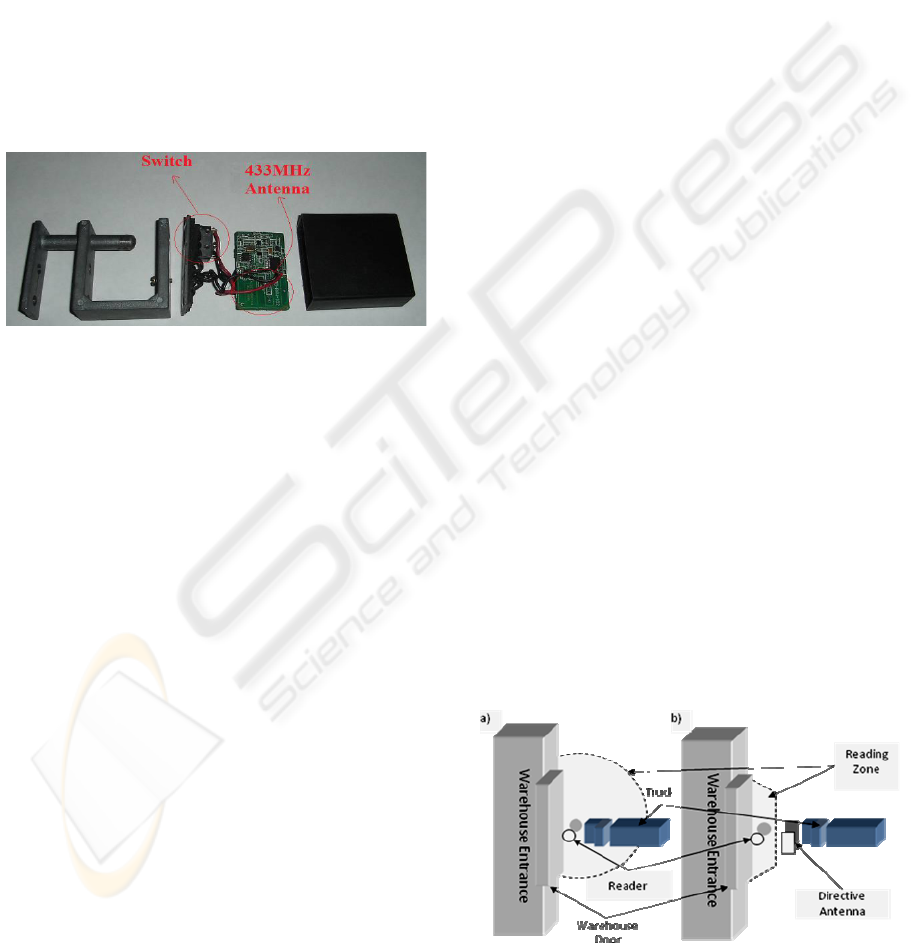
To work as an electronic seal, a tamper sensor
was attached to the tag. This sensor accuses “ok”
status if its terminal were placed in short circuit and
“violated” if the terminal were open circuit. This
feature allowed the development of a tag model that
could be fixed at a truck's dump-cart, seen in Figure
1. If occurs a tag removal attempt, the tamper sensor
would detect and send a violation signal to the
nearest reader.
The main difficulty found in the tag design was
towards the great difference between trucks used by
the company, which made difficult to develop a
single tag that could be fixed in each of them. To
solve this problem, the tag was designed be similar
to a padlock that can be fixed in any bar up to two
inches thick, common in all kinds of truck.
Therefore, it was possible to fix a tag in multiple
parts of the truck. The violation detection of a tag is
made throughout a small switch, that when the lock
is closed, this switch is pressed and when the lock is
opened, the switch is released. This switch was
connected from two wires to the tag's circuit
violation terminals sensor.
The adopted rule to install readers was: at each
entrance and exit was installed a reader. For
example, at the weighting scale platform were
installed two readers, one at the entrance and another
at the exit. At the unloading warehouses, one reader
was put at each entrance/exit gate. All readers were
connected by Unshielded Twisted Pair (UTP) cables
Cat 5e. Warehouses and weighting scales were
connected by multimode optical fiber cables due the
long distance between readers’ installation point and
the server. The optical fiber and the UTP Cat 5a
cables create a local area network between all
devices and the server which executes managing
application. So, each truck's passage through a
reader generates a data packet to the server with
information containing the tag's identification,
electronic seal status, timestamp and the
identification of the reader that received the packet.
3 DIRECTIVE ANTENNA
The place where the tag is attached on each truck
may vary depending on the truck’s dump-cart, and
the material of it can vary between wood and steel as
well. These variations can influence in the
sensitivity of the tags, causing undesired tag
readings outside the calibrated reader reading range.
These readings happen when the truck is crossing in
front of the warehouse entrance, causing unexpected
alarms and making the system calls the security
team unnecessary. To solve this problem, two
resources were used: a directive antenna and the
Received Signal Strength Indication (RSSI) feature
of the reader (Foina, 2006).
This antenna will amplify the signal received in
its directive lobule, sending a stronger signal to the
reader in this case. But, if the signal is received
outside its directive lobule, the reader will receive a
weak signal (Balanis, 1997). The antenna used has
an E-Plane and H-Plane beamwidth of 65 degrees at
3dB, circular polarization and 7 dBi of gain.
The RSSI feature of the active readers allows the
measurement of the signal strength received by the
reader. In the chosen equipment, the RSSI is an
index from 0 to 255, where a higher value means a
stronger signal.
With the RSSI and the directive antenna, the
software can analyse the RSSI to check if the tag is
behind or in front of the antenna. The directive
antenna was installed behind the reader, facing to the
warehouse door, approximately 1 meter away
according to the Figure 2.
Figure 2: Aerial representation of the reading zone of both
approaches, a) using the omnidirectional antenna and b)
using the directive antenna.
Figure 1: Active tag in a padlock shape with opening
detector disassembled.
HUNTER – HYBRID UNIFIED TRACKING ENVIRONMENT - Real-time Identification and Tracking System using
RFID Technology
323
When the tag is close to the door, but behind the
antenna, the RSSI index will be very low because
the tag is not in the main lobule of the antenna.
When the tag is positioned between the door and the
antenna, the RSSI index will be much higher than if
measured in the same position with an
omnidirectional antenna. This enables the
middleware to make the decision of whether or not
granting access into the warehouse.
4 MANAGING APPLICATION
The managing application developed, called Hybrid
Unified Trekking Environment (Hunter), controls
the unloading process information over the
monitored vehicle. Every truck is treated by the
system as an event queue to be executed. Inside the
system, every truck's passage through an
entrance/exit is an event. Full weight, unload and
empty weight are examples of events to be executed
by the truck. Thus, in the system, each truck has a
state within a finite state's machine. Through
received events by that truck, it registers exactly in
which stage of unloading flow the truck is in real-
time. In other words, the trucks in movement inside
the area are treated as independent threads in the
system, which is initiated when its tag passes by the
weighting scale to capture the full weight,
generating the first event. When these threads are
created, a task queue at the data base is created as
well, with all the tasks the truck must accomplish
along the process, such as: weighting scale entrance
for full weight, full weight capture, weighting scale
exit, unloading area entrance, etc. While the truck
moves and generates the events, these are interpreted
by the system and converted into its respective tasks,
and thus they are removed from the task queue and
inserted in the journal table. In case the tasks orders
are not obeyed, an alarm is generated on the system
operator's screen.
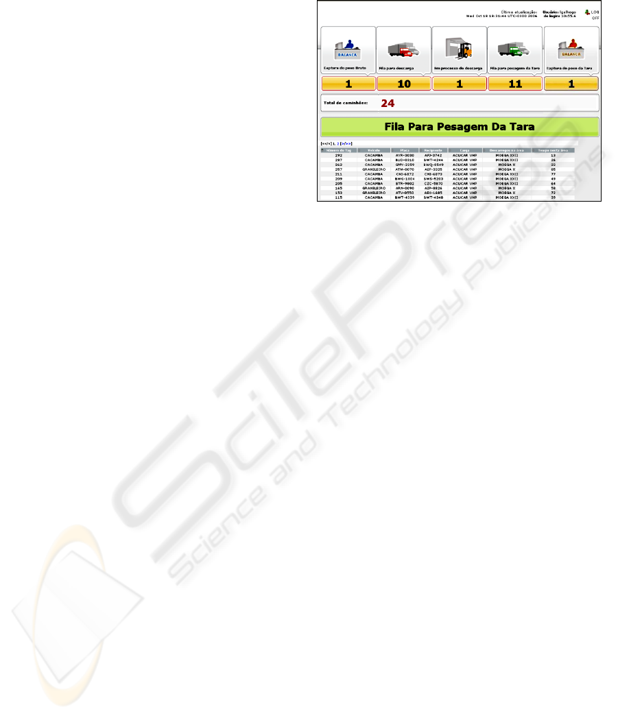
The system graphical interface shows the number
of trucks on each state of the unloading process,
seen in Figure 3. The numbers of trucks in the lines
between each state are showed as well. So, there are
five states presented in the interface: Full weight
capture, Unload line, Unloading process, Empty
weight line and Empty weight capture. Through the
graphical interface, it is possible to see the trucks
that are in this state and how long they are there.
The application was totally developed in Java,
being a part of it monolithic and a part in form of a
web-base application. It is executed by a Tomcat
application server and connected to an Oracle 9i data
base with features of advanced task queue. As
different technologies are used, the managing
application was developed with modules, divided in
three layers (Chen, 2003).
Figure 3: Hunter’s screenshot showing the number of
trucks in each state.
The first system layer, called Device
Management Subsystem (DMS) is the layer
responsible for the connection between the physical
device, in this case RFID readers, and the system
engine for process control, times and alarms, called
here as Core. The DMS stays waiting for a package
at the serial port or at the Ethernet connections, and
when it receives a data sent by any device, it
interprets the information and generates a message
in Extensible Markup Language (XML) with
information about the devices positioning, the name
of the place where the tag was read and details about
the truck which has read tag attached. to be sent to
Core. DMS is a middleware, connecting different
devices in the system at the same time, and allow
new devices to be connected to the system without
any change in the source code of the application.
The Core has a servlet that receives the XMLs
from DMS and inserts them into the data base.
When this insertion is made, the table where the
information is stored has a trigger that initiates all
the data analysis process, such as the alarms that can
be generated due to this event or updates on truck’s
state in the unloading process. Connected to Core,
there is the interface layer with two other modules,
the graphical interface and the legacy integration
systems. The first one is responsible for presenting
information on the screen, such as alarms,
navigation maps and reports. The second module is
responsible for sending information to the
company's legacy system, updating the warehouse
stock, linking timing information and alarms
generated to the company's Warehouse Management
System (WMS).
ICINCO 2008 - International Conference on Informatics in Control, Automation and Robotics
324

All communication between system modules is
made through XML messages and all system
graphical interfaces are web-based, allowing its
access from any computer without needing specific
application installation, just a conventional web
browser. The integration of the managing
application with the company's corporative systems
is made through recorded text files containing the
XML messages in a shared directory due limitations
of the company legacy system.
5 CONCLUSIONS
Despite the difficulties installing a wireless network
and an optical fiber network in old warehouses, and
placing sensible radio frequency equipment exposed
to weather hazards, it was possible to install
successfully all equipment and do their calibration.
The server applications behaved correctly when
were placed an amount of 200 trucks simultaneously
circulating around the area and unloading the cargo.
Some unexpected problems happened and they
were solved. The switch installed inside the padlock
tag changed the inductance of the 433MHz antenna,
so the internal organization of the tag was changed
to keep the antennas as far as possible from the
switch. Sometimes the truck parks in front of the
reader, generating many readings of the tag, but
sometimes the readings happed before the truck left
the place. For this reason, filtering controls were
implemented inside the DMS to avoid generation of
fake alarms.
The system helped the company management
and security. With the additional information
generated by the system for the logistic department
about the weight, unload time statistics, and the
number of trucks in real time in each stage of the
unloading process, it was possible to optimize the
trucks' line, reducing the wait in line and therefore,
reducing the average time of the unload process
from 50 minutes to 30 minutes. The installation of
RFID padlock tags in the trucks reduced in 60% the
load theft in the port area and allowed the security
team to find out points of vulnerability of the
previous system and to detect the majority of the
truck drivers corrupted by the theft group.
This same system showed flexible enough to be
used with other RFID technology and applications,
like passive tags to control automated manufacture
lines, supply chain pallets and forklifts. In this case
the application will control if the item pass through
all the phases in manufactory line, from the
beginning until the expedition. Can control who was
the forklift operator and how long he took to move
the products from one place to other. So the product
will be tracked, supplying information about the
storing and movement time, and the forklifts will be
tracked as well, supplying information about the
efficiency of the forklift operator and generating
alarms if he does something wrong.
REFERENCES
Almanza-Ojeda, D. L.; Hernandez-Gutierrez, A.; Ibarra-
Manzano, M. A.; 2006. Design and implementation of
a vehicular access control using RFID. In Electronics
and Photonics, 2006. MEP 2006. Multiconference on
2006, pp. 223 – 225.
Balanis, C. A.; 1997. Antenna Theory: Analysis and
Design. John Wiley & Sons, USA, second edition, pp.
86-88.
Blythe, P.; 1999. RFID for road tolling, road-use pricing
and vehicle access control. In RFID Technology (Ref.
No. 1999/123), IEE Colloquium on 25 Oct. 1999, pp.
8/1 – 816.
Chen, S.; Gulati, S.; Hamid, S.; Huang, X.; Luo, L.;
Morisseau-Leroy, N.; Powell, M. D.; Zhan, C.; Zhang,
C; 2003. A three-tier System Architecture Design and
Development for Hurricane Occurrence Simulation. In
Information Technology: Research and Education,
2003. Proceedings International Conference, pp. 113
– 117, 11-13 Aug. 2003.
Foster, P.R.; Burberry, R.A.; 1999. Antenna problems in
RFID systems. In RFID Technology (Ref. No.
1999/123), IEE Colloquium on 25 Oct. 1999, pp. 3/1 - 3/5.
Foina, A. G.; Barbin, S. E.; Ramirez Fernandez, F. J.;
2007. A New Approach for Vehicle Access Control
using Active RFID Tags. In IMOC - International
Microwave and Optoelectronics Conference, 2007.
Proceedings of the 2007 IMOC.
Kim, T.; Kim, H.; 2006. Access Control for Middleware in
RFID Systems. In Advanced Communication
Technology, 2006. ICACT 2006. The 8th International
Conference Vol. 2, 20-22 Feb. 2006, pp. 1020 – 1022.
Ni, L. M.; Liu, Y.; Lau, Y. C.; 2003. LANDMARC:
Indoor Location Sensing Using Active RFID. In IEEE
International Conference in Pervasive Computing and
Communications, 2003, pp. 407-415.
Raza, N.; Bradshaw, V.; Hague, M.; 1999. Applications of
RFID technology. In IEE Colloquium on, 25 October,
1999, pp. 1/1 - 1/5.
Tuttle, J.R.; 1997. Traditional and emerging technologies
and applications in the radio frequency identification
industry. In Radio Frequency Integrated Circuits
(RFIC) Symposium on, 8-11 Jun. 1997, pp. 5 – 8.
Zhao, J.; Zhang, Y.; Ye, M.; 2006. Research on the
Received Signal Strength Indication Location
Algorithm for RFID System. In Communications and
Information Technologies, 2006. ISCIT '06.
International Symposium on Oct. 2006, pp. 881 – 885.
HUNTER – HYBRID UNIFIED TRACKING ENVIRONMENT - Real-time Identification and Tracking System using
RFID Technology
325
