COMPARATIVE STUDY OF ROBOT-DESIGNS FOR A
HANDHELD MEDICAL ROBOT
Peter P. Pott, Markus L. R. Schwarz
Laboratory for Biomechanics and experimental Orthopaedics, OUZ, Medical Faculty Mannheim
University of Heidelberg, Theodor-Kutzer-Ufer 1-3, 68167 Mannheim, Germany
Achim Wagner, Essameddin Badreddin
Automation Laboratory, University of Mannheim, Mannheim, Germany
Keywords: Hybrid kinematics, Medical robotics, Comparison.
Abstract: Robotic systems are used within a great variety of medical disciplines. A handheld robot promises a number
of advantages compared to conventional (medical) robots but this approach leads to strict specifications
regarding size, weight and dynamic properties. A new hybrid kinematics – the Epizactor – seems to be
advantageous and is compared to two well-known parallel kinematics regarding the ratio of workspace and
volume the number of kinematic elements, the cost of computation, the stiffness the effects of clearance,
actuation (weight), and accuracy using a well-described industrial method for comparison. It becomes clear
that the Epizactor has advantages concerning the ratio of workspace and volume, needs a smaller number of
kinematic elements and fewer computations, and has less than half the mass than the parallel kinematics. Its
accuracy, stiffness and the effects of clearance are comparable. The advantages of this new kinematic set-up
lead to a first deployment within the field of medical robotics.
1 INTRODUCTION
Design and evaluation of robotic set-ups for medical
and especially surgical applications has been
ongoing for the last 20 years. Systems for a vast
variety of medical disciplines and deployments have
been investigated (Pott PP et al., 2005). One possible
solution to provide a useful tool for numerous
medical tasks is to use a handheld robot that
combines the process control of the surgical task by
the surgeon and the accuracy and repeatability of a
robot. Within the project "Intelligent Tool Drive"
ITD, a handheld robot for orthopaedic surgery is
being developed. The intention is to align a milling
tool relatively to a patient and to decouple the tool
from unintentional hand movements at the handle
(Pott PP et al., 2003; Wagner A et al., 2004). A
handheld robot has to be as small and lightweight as
possible while providing high dynamics for accurate
stabilisation of a surgical tool (Wagner A et al.,
2004). This most important criterion is mainly
determined by the kinematic set-up.
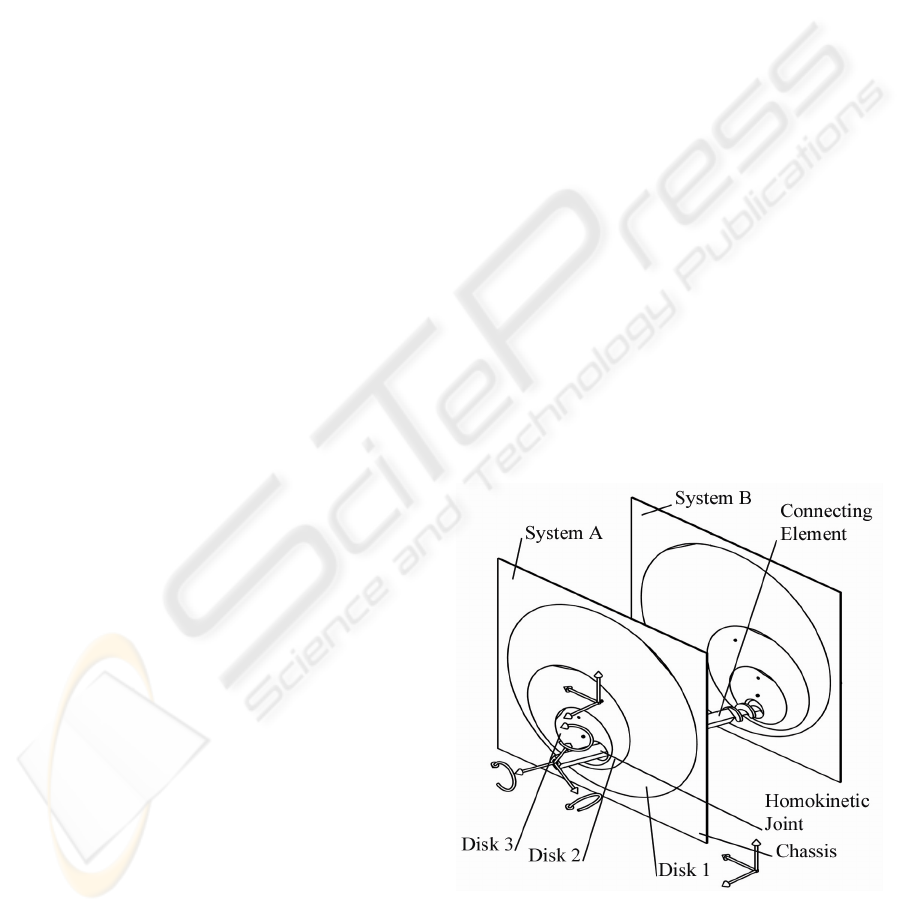
Figure 1: The EPIZACTOR, 6-DOF hybrid kinematics
with rotating elements.
Parallel robots are widely used, where high
stiffness, high dynamics, or low error propagation
103
P. Pott P., L. R. Schwarz M., Wagner A. and Badreddin E. (2008).
COMPARATIVE STUDY OF ROBOT-DESIGNS FOR A HANDHELD MEDICAL ROBOT.
In Proceedings of the Fifth International Conference on Informatics in Control, Automation and Robotics - RA, pages 103-110
DOI: 10.5220/0001494001030110
Copyright
c
SciTePress
over the kinematic chains is required, e.g.
positioning and stabilization platforms (Huynh P,
2001) and vibration isolation (Chen Y et al., 2004).
An obvious advantage is that a parallel robot
provides high potential for a lightweight
construction. The moving masses of parallel
kinematics are low and this leads to low static and
dynamic forces (Honegger M, 1999; Huynh P,
2001).
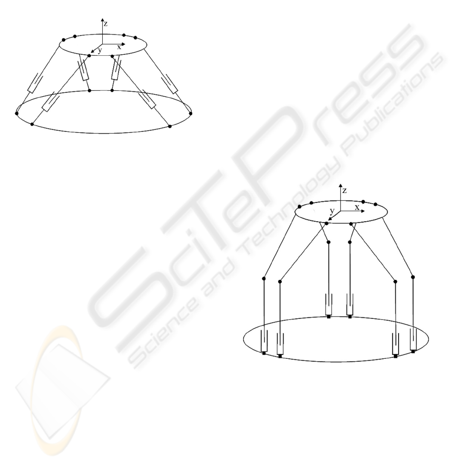
Figure 2: The HEXAPOD, 6-DOF parallel kinematics
with actuated prismatic joints in the struts.
Alternatively a new kinematic set-up can be used
(). This concept –called "Epizactor"– involves two
disk-systems (systems A&B) each described by a
planar 3-DOF 4-link manipulator. These two serial
kinematic chains act on a connecting element that
moves the surgical tool by homokinetic joints with a
lead-screw and a prismatic section respectively.
Each disk-system uses four links to overcome
singularities by redundancy. So this hybrid
kinematics uses only rotating elements to provide 6-
DOF manoeuvrability (Pott PP et al., 2007; Pott PP,
Weiser HP et al., 2004).
The aim of this work is the comparison of a new
kinematic set-up with two well-known alternatives
for a handheld medical robot.
2 MATERIAL & METHODS
Three different kinematic set-ups were assessed. The
well-known Stewart-Gough-platform or Hexapod
(Figure 2) with active struts (Gough V et al., 1962;
Stewart D, 1965), the Merlet-platform or Hexaglide
(Merlet JP, 1988) with base-fixed actuators and
passive struts (Figure 3) and the Epizactor (Pott PP
et al., 2007; Pott PP, Weiser HP et al., 2004) (). The
first two set-ups are based on parallel kinematics
while the Epizactor is based on a hybrid kinematics
set-up. To describe the set-ups' forward and inverse
kinematics as well as the inverse dynamic models a
literature research and own considerations were
conducted. For the assessment of the actual
mechanical design three robots were available. Each
is based on one of the kinematic set-ups described
and shows a certain state of project ITD.
2.1 Comparison
To compare the kinematic set-ups the method by
Kesselring (Kesselring F, 1951) is used. Here a set
of criteria is defined and evaluated by one or more
experts using a score reaching from 4 (very good) to
1 (poor). To further refine the comparison, each
criterion is weighted. Finally for each kinematic set-
up the sum of all products of score and weight are
added up and lead to a total benchmark for each
kinematic set-up. To define the weighting factors the
method described by Wenzel (Wenzel R et al., 1971)
is used. Here all criteria are listed and each criterion
is compared to the remaining leading to a graduation
in importance of the different criteria.
Figure 3: The HEXAGLIDE, 6-DOF parallel kinematics
with base-fixed actuates prismatic joints.
To assess the three kinematic set-ups the
following criteria were used.
ICINCO 2008 - International Conference on Informatics in Control, Automation and Robotics
104

2.2 Ratio of Workspace and
Installation Space
Given a certain workspace needed for a specific
task, this ratio describes how large a machine will
become at least. Especially in a surgical
environment the installation space should be as
small as possible while the workspace is determined
by the surgical task.
To assess this ratio each kinematic set-up was
simulated using Matlab (The Mathworks Inc,
Natick, MA, USA) and a given workspace definition
of 40mm translation of the tool in each axis and
±20° rotation in each axis at all times. Using this
simulation procedure the three kinematic set-ups
were scaled until predefined kinematic restrictions
were just not violated but the desired workspace
could still be produced. Each kinematic set-up is
circumscribed by a cylinder that defines the minimal
installation space of an imaginary machine based on
the corresponding kinematics. The length of the
cylinder is aligned with the tool nearest to the base-
platform.
2.3 Number of Kinematic Elements
Kinematic elements are defined as "joints", "struts"
or "links", "base", and "tool". The number of
kinematic elements can be used as a measure of
complexity of a kinematic set-up (El-Shenawy A et
al., 2007).
To assess the number of kinematic elements each
kinematic set-up was analysed and the elements
were counted.
2.4 Cost of Computation
The cost of computation can be a measure for the
hardware-effort that has to be made by the control
system to compute the forward and inverse
kinematic problems in real-time.
To assess the cost of computation for each
kinematic set-up the Matlab-code was analysed
regarding the number of additions,
multiplications/powers and trigonometric functions.
To compare the three set-ups a computation of both
kinematic problems was concerned and all
computation steps were summed up. The set-up with
greatest number was rated "1" the one with the
smallest number was rated "4". In between a linear
interpolation was performed.
2.5 Stiffness
Although stiffness is not a kinematic property and
system stiffness is mainly affected by the actual
design of a machine the three set-ups can be
analysed qualitatively regarding the distribution of
forces within the kinematic elements. It can be stated
that short and compact elements under uniaxial load
will be stiffer than flat elements under bending
strain.
To analyse the three set-ups the kinematic
elements were examined regarding the distribution
of force and shape.
2.6 Effects of Clearance
As it can be regarded as one of the major
impediments for accurate machine performance
clearance becomes one of the most important
criteria. Again this is not a purely kinematic feature
but the kinematic set-up has an influence on error
propagation.
To assess the effects of clearance a score
especially for the assessment of parallel and hybrid
kinematics was introduced (Pott PP, unpublished). It
was assumed that the clearance k
i
of i joints of a
serial kinematic chain in the most unfavourable case
is summed up to
∑
=
i
isertot
kk
,
(1)
For the parallel arrangement of j serial chains it
is assumed that the clearance can be treated as
()
∑
=
j
serjpartot
kk
2
,,
(2)
For simplification the clearance in any joint is
standardised to "1".
2.7 Actuation / Weight
The actuation of a robot is not a kinematic property
but becomes important when size and weight of the
actual machine is evaluated. Electromagnetic linear
actuators provide high acceleration but a poor force-
to-weight ratio. Correspondingly conventional
COMPARATIVE STUDY OF ROBOT-DESIGNS FOR A HANDHELD MEDICAL ROBOT
105

rotating motors deliver high power at high speeds
but poor torque when used without gearing (Pott PP,
unpublished). So the actuation has an immanent
influence on the weight of a machine based on a
certain kinematic set-up.
To assess the three kinematic set-ups they were
analysed regarding performance needed and
theoretical weight. To determine the strut forces of
the Hexapod and the Hexaglide corresponding
dynamic models were used (Dasgupta B et al., 1998;
Khalil W et al., 2004; Wagner A et al., 2006).,
dynamic models (Dasgupta B et al., 1998) were
used. The Epizactor was assessed using a model
based on the iterative Newton-Euler-Method and
own considerations regarding the forward- and
inverse kinematic problems (Pott PP et al., 2007). As
input for the simulation a vibration trajectory with
12Hz and 1mm amplitude was used. This trajectory
was applied to each of a set of 680 pre-defined grid-
points throughout the whole desired workspace.
Additionally the direction of the trajectory and the
static forces
[]
NF
T
202020=
and moments
[]
NmM
T
8.011=
were permutated in the main
coordinate system directions. Forces, moments,
frequency (velocity, acceleration) were taken from
the specifications of the handheld robot (Pott PP et
al., 2003; Pott PP, Wagner A et al., 2004). Masses
and mass-related values of the kinematic elements
were taken from the CAD-models of the three
available robots. The maximum forces and torques
in each actuator were computed. For the parallel
kinematics this force was multiplied by six, as the
symmetry of the set-up leads to the conclusion that
any actuator will have to be able to produce this
force. Regarding the Epizactor the torques of all
actuators were summed up. To achieve the
theoretical weight of the actuators of each set-up the
over-all force was multiplied with the specific force-
to-weight-ratio of the linear actuators and the
rotating actuators respectively. It could be shown
from manufacturer's data that an average electric
linear motor with a maximum force of about 50N
(30s) has a force-to-weight ratio of about 47.2N/kg.
The torque-to-weight ratio of an average motor with
a gear that allows a torque of 1Nm is about
3.4Nm/kg (Pott PP, unpublished).
2.8 Accuracy
The accuracy of a robot is determined by the
accuracy and resolution of sensors and actuators, the
adjustment of control parameters, the elastic
properties of the mechanics, and the transformation
of workspace coordinates into actuator axis
positions. As the first three parameters are affected
by the actual mechanical design, the latter is
dependent on the kinematics-type and actual
configuration only.
To assess the theoretical accuracy the tolerable
position error of the robot of 0.1mm (Pott PP et al.,
2003) was applied to the set of grid-points described
above. Doing so, the displacement of the actuators
was computed and compared to a realistic accuracy
of 0.005mm and 0.0005rad respectively, which can
be reached by real encoders used in a mechanical
design. A score was introduced that describes the
number of points where the accuracy specification is
reached.
3 RESULTS
3.1 Comparison
Table 1 shows a summary of the results for each
kinematic set-up. The comparison criteria are
aligned in rows. The columns show results, ratings
and weighted scores for each of the three kinematic
set-ups. The results of the comparison and a ranking
are summed up in the bottom line. It becomes clear
that the Epizactor has advantages regarding the ratio
of workspace and installation-space and theoretical
weight of its actuators. Additionally it needs less
kinematic elements, uses rotating actuators that
provide a better performance-to-weight ratio than
linear motors, and needs fewer computations for the
inverse and direct kinematic problem. Main
disadvantage of this new kinematic set-up is the
limited stiffness.
3.2 Ratio of Workspace and
Installation Space
The Hexapod can be enclosed by a cylinder with a
minimal volume of 3941cm³. This leads to a ratio of
workspace and installation space of 1:62.
The cylinder around the Hexaglide has a
minimal volume of 4247cm³ so the ratio of
workspace and installation space can be computed to
1:66.
A cylinder circumscribing the Epizactor has a
volume of 1445cm³. Compared with the required
workspace this leads to a ratio of workspace and
installation space of 1:23.
ICINCO 2008 - International Conference on Informatics in Control, Automation and Robotics
106

3.3 Number of Kinematic Elements
The Hexapod and the Hexaglide each consist of a
base-platform, a tool-platform, and six legs. Each
leg uses two rotating and one prismatic (actuated)
joint and a strut. Overall 26 kinematic elements can
be counted.
The Epizactor consists of a base, a connecting
element (tool) and two identical disk-systems. Each
disk-system has 3 disks and a homokinetic joint. The
first disk is actuated directly. To drive the 2
nd
disk a
single toothed ring is necessary, to drive the 3
rd
disk
two toothed rings are used and the joint is driven by
three rings. Overall 22 kinematic elements can be
counted.
3.4 Cost of Computation
To calculate the Hexapod's inverse kinematic
problem 60 additions, 132 multiplications and
powers, and 174 trigonometric functions have to be
computed. The forward kinematic problem can only
be solved by an iterative procedure. Within the
simulations carried out around 40 iteration steps
were necessary for each computation. To compute
the kinematics once in both directions 15086
computations have to be carried out.
For the Hexaglide the inverse kinematic problem
is solved in the same way and also the forward
kinematics needs to be computed by iterations. Here
around 10 iteration steps were necessary. To
compute the kinematics once in both directions 4046
computation steps have to be done.
The inverse kinematic problem of the Epizactor
needs 106 additions, 171 multiplications and
powers, and 132 trigonometric functions. The
forward kinematics are computed by 31 additions,
115 multiplications and 177 trigonometric functions
(Pott PP, unpublished). To compute the kinematics
once in both directions 732 computations have to be
carried out. One has to consider that the inverse
kinematic problem finally is solved by a singularity-
robust control algorithm (Chung YG et al., 2000;
Pott PP et al., submitted) and does not need to be
computed.
3.5 Stiffness
The struts of the Hexapod kinematics can be
regarded as pendulum links. Each of the struts is
loaded by pressure and tension which must be fully
Table 1: Summary of the results and comparion of the three kinematic set-ups assessed. The comparion criteria are
aligned in rows, the results of the comparison, the rating, and weighted results are listed in columns. The bottom lines
show the result and the ranking of the three kinematic set-ups. The higher the result the better the set-up is suited for the
assessed deployment.
Hexapod Hexaglide Epizactor criteria unit weight
results rating result
rating
results rating result
rating
results rating result
rating
Ratio of
Workspace
and Instal-
lation Space
1 0.28 1:62 2 0.56 1:66 2 0.56 1:23 4 1.12
Number of
Kinematic
Elements
1 0.09 26 3 0.27 26 3 0.27 22 4 0.36
Cost of
Computa-
tion
score 0.02 15086 1 0.02 4046 3.36 0.07 732 4 0.08
Stiffness
rating 0.14
high and
constant
stiffness
4 0.56
high but
variable
stiffness
3 0.42
medium
stiffness
2 0.28
Effects of
Clearance
score 0.19 7.3 2 0.38 7.3 2 0.38 7.1 2 0.38
Actuation /
Weight
kg 0.19 7.1 1 0.19 5.6 2 0.38 2.2 4 0.76
Accuracy score 0.09 300 1 0.09 440 2 0.18 420 2 0.18
Results of
the compa-
rison
2.07 2.26 3.16
Ranking 3 2 1
COMPARATIVE STUDY OF ROBOT-DESIGNS FOR A HANDHELD MEDICAL ROBOT
107

absorbed by the actuated prismatic joint in each
strut. As the passive parts in each strut can be
designed as stiff as necessary the stiffness of the
prismatic joint depends on its design, the
construction of the actuator, and the quality of the
control loop. The stiffness of the struts is almost
constant over the length so it can be stated that the
over-all stiffness of the Hexapod in its workspace is
constant.
To consider the stiffness of the Hexaglide a
similar approach can be used. Differences exist as
the struts of the Hexaglide usually tend to be as light
as possible as they do not need to be actuated. Also
two variations of parallel kinematics with base-fixed
actuation exist. One that uses sliders (Hebsacker M
et al., 1998), here the over-all stiffness within the
workspace can be seen as constant. The version that
uses piston-like actuators (Merlet JP, 1988) provides
lower stiffness for extended actuators and changing
over-all stiffness within the workspace.
Forces applied to the connecting element of the
Epizactor are propagated to the disk-systems and
absorbed within the planes of the disk systems. The
stiffness of the disk-systems in this direction is
rather good. Only the force-component within the
axis of the connecting element acts perpendicular to
disk-system B so that here the stiffness is less good.
The stiffness is constant within the workspace as the
connecting element can be designed as stiff as
necessary.
3.6 Effects of Clearance
The Hexapod is based on six identical kinematic
chains between base-platform and tool. Each chain
consists of three joints. The clearance k
tot,ser
of each
chain is computed to
3111
,
=++==
∑
i
isertot
kk
. (3)
For the whole set-up the score can be computed to
()
3.736
2
2
,,
=⋅==
∑
j
serjpartot
kk
(4)
The same assumptions can be made for the
Hexaglide and lead to a similar result.
The Epizactor uses two serial chains with 5
elements acting in parallel on the connecting
element. The clearance k
tot,ser
of each chain is
computed to
511111
,
=++++==
∑
i
isertot
kk
. (5)
For the parallel arrangement of the two chains,
the overall score can be computed to
(
)
1.755
22
2
,,
=+==
∑
j
serjpartot
kk
. (6)
3.7 Actuation / Weight
The simulations for the Hexapod lead to maximum
forces of 55.7N in each strut. Thus the six actuators
needed to drive the Hexapod weighs at least 7.1kg.
For the Hexaglide the maximum force needed to
drive the set-up is 44.4N. With the same
considerations regarding the force-to weight-ratio
the actuators theoretically weigh about 5.6kg.
The Epizactor has a maximum torque
requirement in the specific actuators of 1.33Nm,
1.53Nm, 0.94Nm, 0.8Nm, 0.95Nm, 1.52Nm,
0.26Nm, and 0.02Nm. So the theoretical weight of
all actuators of the Epizactor sums up to 2.2kg.
3.8 Accuracy
The Hexapod can provide the desired kinematic
accuracy in 300 of the tested 680 grid-points. These
points are located near the main xz- and yz-plane of
the base-platform.
The Hexaglide reaches the desired accuracy in
440 of the tested grid-points. These are distributed
symmetrically to the main xz-plane of the base.
Within a small strip just next to this plane the
accuracy is not reached.
The Epizactor reaches the accuracy specification
on 420 grid-points. These are symmetrically
distributed within the workspace. The desired
accuracy is not reached at points were a certain
configuration of the disks leads to a very sensitive
behaviour of the kinematics.
4 DISCUSSION
Three different kinematic set-ups have been
evaluated. The method to compare the three
kinematic set-ups refers to the German norm VDI
2222. This method leads to a reproducible result
when it is done out by a group of experts. Here a
single expert carried out the comparison so a certain
bias can be assumed. However as primarily
measurable criteria were evaluated, the bias is
believed to be small. The graduation of the ratings is
rather raw but this simplifies the rating itself. It
becomes obvious that the Epizactor provides a
ICINCO 2008 - International Conference on Informatics in Control, Automation and Robotics
108

number of advantages when compared to two well-
known parallel kinematic set-ups. This lead to the
decision to design such a set-up within the medical
robotics project ITD and for future projects.
It could be shown, that the ratio of desired
workspace and theoretical installation space of the
Epizactor is about three times better when compared
to the well-known parallel kinematics. The desired
workspace is derived from the specifications of the
ITD project and is described by a cube. If another
workspace-specification is taken into account, the
comparison will produce different results. The
method to simulate the desired workspace and to
scale down the kinematic set-up does not lead to an
optimization but seems to approximate the actual
set-up to this point. This criterion is the most
important within the comparison.
The Epizactor needs a smaller number of
kinematic elements than the Hexapod or the
Hexaglide. However the larger number of common
parts within the parallel kinematics simplifies the
actual manufacturing of those kinematic set-ups.
The fact that there seems to be no closed-form
solution for the inverse kinematics of the Hexapod
and the Hexaglide leads to a large number of
computations for the forward kinematic problem. In
contrast the mathematically well-defined kinematics
of the Epizactor leads to only a small number of
computations. It has to be considered that the code
analysed for comparison is not optimised. Although
the cost of computation is unequally distributed
between the three kinematic set-ups this criterion has
the least importance, as today's computer
performance allows even large computations in real-
time.
Stiffness is depending on the actual design of a
machine and is not an original kinematic property. It
is affected by the force distribution in the kinematic
set-up and therefore can be regarded quite important
as it applies to the robot's accuracy. Here stiffness is
analysed qualitatively and leads to the conclusion
that the Epizactor appears to be less stiff as forces
are distributed through flat rotating elements rather
than by robust pendulum supports utilised by the
parallel kinematics.
Although the effect of clearance is the second
most important due to accuracy reasons the
differences between the three set-ups are marginal as
it could be shown by the score that was introduced.
This can be explained by the fact that the length of
the kinematic chains and their quantity compensate
for each other. One has to remark that this score can
only be applied to parallel kinematics and that
experimental results have not yet been made to
substantiate this comparison.
While actuation is not a kinematic property this
criterion is used to evaluate a theoretical weight of
the actuators and hence for the weight of a
hypothetically realised machine. During the work on
the ITD-project it became obvious that linear
actuators seem to provide an unfavourable ratio of
force and weight, so that a machine driven by such
actuators becomes heavier than a machine driven by
rotating actuators considering comparable
performance. This also applies when rotating
spindles are used because of their additional weight.
The parallel kinematics are 3.2 times (Hexapod) and
2.5 times (Hexaglide) heavier than the Epizactor due
to the use of rotating actuators in this set-up and its
more favourable dynamic properties.
The resolution and accuracy of sensors for linear
displacement and rotating angles are limited. So the
accuracy of a machine based on a certain kinematic
set-up is not only limited by mechanical precision,
elasticity and the quality of the control loop but also
by the kinematic transformation of tool and axis
coordinates. The Epizactor's coordinate
transformation seems to be advantageous here.
The discrimination between purely kinematic
properties and features of the technical realisation is
not easy. This seems not to be a disadvantage as the
idea of the Epizactor aims to a practical use of the
kinematics in a handheld medical robot.
5 CONCLUSIONS
The Epizactor is a new kinematic concept for a small
6-DOF robot. A first deployment of this approach
will be a handheld robot for medical applications.
Here sharp restrictions regarding size, weight and
workspace exist and it could be shown, that the
Epizactor meets the main specifications in a most
favourable way.
ACKNOWLEDGEMENTS
The work on the ITD-project is supported by the
AiF, Berlin, Germany and has been supported by the
German Research Society. The work on the
Epizactor has been supported by the state of Baden-
Württemberg, Germany. The authors want to
express their most sincere gratitude to Prof. P.
COMPARATIVE STUDY OF ROBOT-DESIGNS FOR A HANDHELD MEDICAL ROBOT
109

Weiser and Mr. Steffen Heute who both contributed
greatly to the development of the Epizactor.
REFERENCES
Chen Y, & McInroy JE. (2004). Decoupled control of
flexure-jointed hexapods using estimated joint-space
mass-inertia matrix. IEEE Transactions on Control
Systems Technology, 12(3), 413- 421.
Chung YG, & Lee B. (2000). Torque Optimizing Control
with singularity-robustness for kinematically
redundant robots. Journal of Intelligent and Robotic
Systems, 28, 231-258.
Dasgupta B, & Mruthyunjaya TS. (1998). A Newton-Euler
formulation for the inverse dynamics of the Stewart-
Platform manipulator. Mech. Mach. Theory, 33(8),
1135-1152.
El-Shenawy A, Wellenreuther A, Baumgart A, &
Badreddin E. (2007). Comparing Different Holonomic
Mobile Robots. Paper presented at the 2007 IEEE
International Conference on Systems, Man and
Cybernetics, Montreal, Canada.
Gough V, & Whitehall S. (1962, oder 1949). Universal
Tyre Test Machine. Paper presented at the IX Int.
Techn. Congr. F.I.S.I.T.A.
Hebsacker M, & Codourey A. (1998). Die Auslegung der
Kinematik des Hexaglide – Methodik für die
Auslegung paralleler Werkzeugmaschinen. Paper
presented at the VDI Fachtagung Parallele Strukturen,
TU Braunschweig.
Honegger M. (1999). Konzept einer Steuerung mit
Adaptiver Nichtlinearer Regelung für einen
Parallelmanipulator. Dissertation, ETH, Zürich.
Huynh P. (2001). Kinematic performance comparison of
linar type parallel mechanisms, application to the
design and control of a hexaslide. Paper presented at
the 5th International conference on mechatronics
technology (ICMT), Singapore.
Kesselring F. (1951). Bewertung von Konstruktionen.
Düsseldorf: Deutscher Ingenieur-Verlag.
Khalil W, & Guegan S. (2004). Inverse an Direct Dynamic
Modeling of Gough-Stewart Robots. IEEE
Transactions on Robotics, 20(4), 754-762.
Merlet JP. (1988). France Patent No. 2628670.
Pott PP. (unpublished). Untersuchung von Kinematiken für
handgehaltene Roboter. Dissertation, Universität
Mannheim, Mannheim.
Pott PP, Scharf H-P, & Schwarz MLR. (2005). Today's
State of the Art of Surgical Robotics. Journal of
Computer Aided Surgery, 10(2), 101-132.
Pott PP, & Schwarz MLR. (2007). The Relation of
Workspace and Installation Space of Epicyclic
Kinematics with six Degrees of Freedom. Zeitschrift
für Biomedizinische Technik, 52(5), 323-336.
Pott PP, Schwarz MLR, Köpfle A, Schill M, Wagner A,
Badreddin E, et al. (2003). ITD - A handheld
manipulator for medical applications - Concept and
design. Paper presented at the 3rd annual meeting of
CAOS, Marbella, Spain.
Pott PP, Wagner A, Badreddin E, & Schwarz MLR.
(submitted). Inverse Dynamic Model and a control
application of a Novel 6-DOF Hybrid Kinematics
Manipulator. IEEE Transactions on Mechatronics.
Pott PP, Wagner A, Köpfle A, Badreddin E, Männer R,
Weiser P, et al. (2004). A handheld surgical
manipulator: ITD - Design and first results. Paper
presented at the CARS, Chicago, Illinois, USA.
Pott PP, Weiser HP, Scharf H-P, & Schwarz MLR. (2004).
A gearing mechanism with 4 degrees of freedom for
robotic applications in medicine. Biomedizinische
Technik, 49(6), 177-180.
Stewart D. (1965). A Platform with six Degrees of
Freedom. Proc. of Mech. Eng., 180(1), 371-386.
Wagner A, Badreddin E, Weiser P, Köpfle A, Männer R,
Pott PP, et al. (2004). System Design and Position
Control of a Handheld Surgical Robotic Device. Paper
presented at the Mechatronics & Robotics Conference,
Aachen, Germany.
Wagner A, Pott PP, Köpfle A, Schwarz MLR, Scharf H-P,
Weiser P, et al. (2006, 12.-14.9.2006). Efficient
inverse dynamics of a parallel robot with two movable
platforms. Paper presented at the MECHATRONICS
2006 - 4th IFAC-Symposium on Mechatronic
Systems, Heidelberg.
Wenzel R, & Müller J. (1971). Entscheidungsfindung in
Theorie und Praxis. Stuttgart: VDI-Seminar.
ICINCO 2008 - International Conference on Informatics in Control, Automation and Robotics
110
